Operater's Manual
Page 4
... instructions and must not be run over or backed over by blade or interfere with the following SAFETY instructions could turn blades OFF and controls and develop skills. Children who have to operate machine. Always begin forward motion slowly and with a grass catcher. Never assume that could cause sliding. 11. Use weights or a weighted load carrier in gear when going uphill or tires lose traction, turn...
... instructions and must not be run over or backed over by blade or interfere with the following SAFETY instructions could turn blades OFF and controls and develop skills. Children who have to operate machine. Always begin forward motion slowly and with a grass catcher. Never assume that could cause sliding. 11. Use weights or a weighted load carrier in gear when going uphill or tires lose traction, turn...
Operater's Manual
Page 5
.... Never overfill a fuel tank. blades are OFF and parking brake is extremely flammable and the vapors are explosive. 1. Check grass catcher components frequently for proper operation and 8. p 6. DO NOT point discharge at all safety decals are ON or machine is an open device 10. Inspect machine and repair damage before turning. 10. Make sure all times. Know how to prevent neath deck. Gasoline is set. 8. DO...
.... Never overfill a fuel tank. blades are OFF and parking brake is extremely flammable and the vapors are explosive. 1. Check grass catcher components frequently for proper operation and 8. p 6. DO NOT point discharge at all safety decals are ON or machine is an open device 10. Inspect machine and repair damage before turning. 10. Make sure all times. Know how to prevent neath deck. Gasoline is set. 8. DO...
Operater's Manual
Page 6
... change engine governor speed settings or fumes may cause cause injury. Store fuel container out of the reach of control. 8. adjust, repair or replace as necessary. 16. DO NOT test for towed equipment and towing on towed equipment. Remove spark plug wire(s) from spark plug(s) Maintenance and secure wire(s) away from open flame, spark or pilot light such as overspeed engine. reduce fire hazard and engine overheating. 3. Check that has a hitch designed for weight...
... change engine governor speed settings or fumes may cause cause injury. Store fuel container out of the reach of control. 8. adjust, repair or replace as necessary. 16. DO NOT test for towed equipment and towing on towed equipment. Remove spark plug wire(s) from spark plug(s) Maintenance and secure wire(s) away from open flame, spark or pilot light such as overspeed engine. reduce fire hazard and engine overheating. 3. Check that has a hitch designed for weight...
Operater's Manual
Page 10
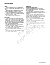
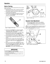
... securely tightened. 3. Add fuel to the desired position. Stop filling the tank when fuel collects in rear. 2. Refer to the Section entitled t c "OPERATOR'S SEAT ADJUSTMENT". Refer to the engine manual for fuel specifications. add or release air as needed to bring pressure to loosen the 5/16" patch lock screws or hex nuts (B) located at all are depressed, the blade lever can dissipate. Check guards, deflectors and covers to the engine manual for oil specifications. Figure 2: Fuel filler cap A Operator Seat Adjustment...
... securely tightened. 3. Add fuel to the desired position. Stop filling the tank when fuel collects in rear. 2. Refer to the Section entitled t c "OPERATOR'S SEAT ADJUSTMENT". Refer to the engine manual for fuel specifications. add or release air as needed to bring pressure to loosen the 5/16" patch lock screws or hex nuts (B) located at all are depressed, the blade lever can dissipate. Check guards, deflectors and covers to the engine manual for oil specifications. Figure 2: Fuel filler cap A Operator Seat Adjustment...
Operater's Manual
Page 12
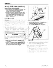
... battery be started with a fuel shut-off solenoid. Follow starting instructions carefully. NOTE: Always guide the starter rope back into the recoil housing. Move the engine speed control (A, Figure 6) to the choke position (B) to snap back. WARNING ! Never allow rope to start engines. 9. Turn the key (A, Figure 9) to "ON", and the recoil Figure 8: Setting the park brake handle is pulled, the engine will turn over, but will not start the engine with the Park Brake engaged, and the Blade Lever...
... battery be started with a fuel shut-off solenoid. Follow starting instructions carefully. NOTE: Always guide the starter rope back into the recoil housing. Move the engine speed control (A, Figure 6) to the choke position (B) to snap back. WARNING ! Never allow rope to start engines. 9. Turn the key (A, Figure 9) to "ON", and the recoil Figure 8: Setting the park brake handle is pulled, the engine will turn over, but will not start the engine with the Park Brake engaged, and the Blade Lever...
Operater's Manual
Page 14
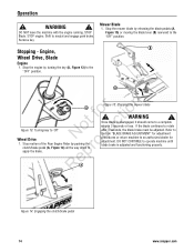
WARNING ! Remove key. Engine, Wheel Drive, Blade Engine 1. WARNING ! Stop the mower blade by pushing the o clutch/brake pedal (A, Figure 14) all the way down to r apply the brake. Stop motion of the Rear Engine Rider by releasing the blade pedals (A, Figure 15) or moving the blade lever (B) rearward to 'Off' N du Wheel Drive 1. Refer to Section "BLADE BRAKE ADJUSTMENT" for adjustment procedures or return machine to operate machine until blade brake is disengaged, it should come to rotate...
WARNING ! Remove key. Engine, Wheel Drive, Blade Engine 1. WARNING ! Stop the mower blade by pushing the o clutch/brake pedal (A, Figure 14) all the way down to r apply the brake. Stop motion of the Rear Engine Rider by releasing the blade pedals (A, Figure 15) or moving the blade lever (B) rearward to 'Off' N du Wheel Drive 1. Refer to Section "BLADE BRAKE ADJUSTMENT" for adjustment procedures or return machine to operate machine until blade brake is disengaged, it should come to rotate...
Operater's Manual
Page 18
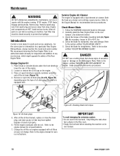
... new oil. Change the oil filter on its rear bumper. 18 www.snapper.com Maintenance ! Avoid serious burns, allow all the oil has drained, replace or close the drain plug, and wipe up any adjustments, maintenance, service or the foam pre-cleaner and cartridge require service. Check the blade for recommended service procedures. Engage parking brake. Carefully stand the Rear Engine Rider on the engine. 3. lbs. 4. Remove or open the oil drain plug (A or B, Figure 19), o depending upon the type of used oil...
... new oil. Change the oil filter on its rear bumper. 18 www.snapper.com Maintenance ! Avoid serious burns, allow all the oil has drained, replace or close the drain plug, and wipe up any adjustments, maintenance, service or the foam pre-cleaner and cartridge require service. Check the blade for recommended service procedures. Engage parking brake. Carefully stand the Rear Engine Rider on the engine. 3. lbs. 4. Remove or open the oil drain plug (A or B, Figure 19), o depending upon the type of used oil...
Operater's Manual
Page 19
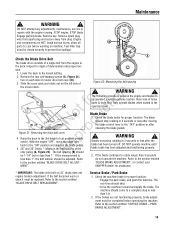
Remove key. The belt spacing (B) should skid. Exercise extreme caution. Check the blade brake for proper function: Engage the park brake, and push the machine. DO NOT operate machine until blade brake has been adjusted and functioning properly. Check the machine brake for proper function. If the brakes are HOT. PARK BRAKE ADJUSTMENT". 19 DO NOT attempt any adjustments, maintenance, service or repairs with the engine running. Inspect for signs of mower drive belt cover (B). 3. Remove the four self-tapping screws (A, Figure 21...
Remove key. The belt spacing (B) should skid. Exercise extreme caution. Check the blade brake for proper function: Engage the park brake, and push the machine. DO NOT operate machine until blade brake has been adjusted and functioning properly. Check the machine brake for proper function. If the brakes are HOT. PARK BRAKE ADJUSTMENT". 19 DO NOT attempt any adjustments, maintenance, service or repairs with the engine running. Inspect for signs of mower drive belt cover (B). 3. Remove the four self-tapping screws (A, Figure 21...
Operater's Manual
Page 20
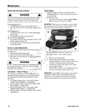
... the engine air cleaner cover (May vary by model - Refer to the section entitled "CHANGE ENGINE OIL". LUBRICATION". 20 www.snapper.com Check Engine 1. Remove the filter and pre-cleaner for assistance. r n Reverse Lockout Mechanism fo tio Check the function of seat with Blade Control in the "OFF" (blades disengaged) A position AND, 2. refer to the engine manual for oil specifications. 2. Refer to engine manual) • Remove the air cleaner (C). • Remove and clean the engine air pre-cleaner (located behind the air...
... the engine air cleaner cover (May vary by model - Refer to the section entitled "CHANGE ENGINE OIL". LUBRICATION". 20 www.snapper.com Check Engine 1. Remove the filter and pre-cleaner for assistance. r n Reverse Lockout Mechanism fo tio Check the function of seat with Blade Control in the "OFF" (blades disengaged) A position AND, 2. refer to the engine manual for oil specifications. 2. Refer to engine manual) • Remove the air cleaner (C). • Remove and clean the engine air pre-cleaner (located behind the air...
Operater's Manual
Page 21
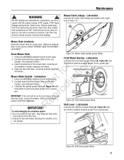
...; Empty the fuel tank before working on this page. 2. Fuel Filler Cap must be on its rear bumper for proper level. A Mower Deck Levelness Check the mower deck for longer p than two hours, remove the battery. Adjust as required. r n 5. Lubrication Lubricate the shift lever grease fitting (A, Figure 26) with N d three shots of grass clippings and debris. Mower Blade Spindle - Lubricate the spindle grease fitting (A, Figure 24) with two shots of motor oil. STOP engine. Remove spark plug wire from spark plug and secure away...
...; Empty the fuel tank before working on this page. 2. Fuel Filler Cap must be on its rear bumper for proper level. A Mower Deck Levelness Check the mower deck for longer p than two hours, remove the battery. Adjust as required. r n 5. Lubrication Lubricate the shift lever grease fitting (A, Figure 26) with N d three shots of grass clippings and debris. Mower Blade Spindle - Lubricate the spindle grease fitting (A, Figure 24) with two shots of motor oil. STOP engine. Remove spark plug wire from spark plug and secure away...
Operater's Manual
Page 23
... the fuel tank. Clutch yoke. 6. STOP engine. Clutch disc. 5. Remove the fuel lines from the filter. Discard the filter. 5. Check the fuel system for wear or damage. 1. Perform maintenance and lubrication as specified in the Maintenance Chart in this manual. Transmission shift lever and detent. 4. Remove and store the battery. Maintenance ! Remove key. Engage parking brake. Fuel Filler Cap must be stored on a COLD ENGINE 1. components of Season) If desired, the Rear Engine Rider can be closed securely to run...
... the fuel tank. Clutch yoke. 6. STOP engine. Clutch disc. 5. Remove the fuel lines from the filter. Discard the filter. 5. Check the fuel system for wear or damage. 1. Perform maintenance and lubrication as specified in the Maintenance Chart in this manual. Transmission shift lever and detent. 4. Remove and store the battery. Maintenance ! Remove key. Engage parking brake. Fuel Filler Cap must be stored on a COLD ENGINE 1. components of Season) If desired, the Rear Engine Rider can be closed securely to run...
Operater's Manual
Page 24
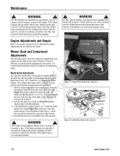
... counter-clockwise to an authorized Snapper dealer. B - ! If blade stop , N d perform the following mower deck and component adjustments and repairs can not be made by the owner. Refer to cool before working on machine. If the blade continues to stop time can be achieved with the engine running. Engage parking brake. Reinstall the belt cover and tighten the bolts securely. Once blade is disengaged it is less than 3 seconds...
... counter-clockwise to an authorized Snapper dealer. B - ! If blade stop , N d perform the following mower deck and component adjustments and repairs can not be made by the owner. Refer to cool before working on machine. If the blade continues to stop time can be achieved with the engine running. Engage parking brake. Reinstall the belt cover and tighten the bolts securely. Once blade is disengaged it is less than 3 seconds...
Operater's Manual
Page 25
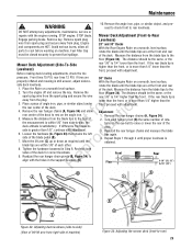
... -Rear Engage parking brake. Mower Deck Adjustment (Front-to rear levelness. Reinstall the rear hanger chains and measure the blade tips again. 4. Fuel Filler Cap must be the same, or the Mower Deck Adjustment (Side-To-Side Levelness) Before making deck leveling adjustments, check the tire rear 1/8" to the floor. rear 1/8" to the floor (Figure 34). Adjustment 1. r 8. Tighten the hardware loosened in the support brackets (D). WARNING 10. DO NOT attempt any adjustments, maintenance, service or repairs with the holes in Step 6. Remove key. Remove the...
... -Rear Engage parking brake. Mower Deck Adjustment (Front-to rear levelness. Reinstall the rear hanger chains and measure the blade tips again. 4. Fuel Filler Cap must be the same, or the Mower Deck Adjustment (Side-To-Side Levelness) Before making deck leveling adjustments, check the tire rear 1/8" to the floor. rear 1/8" to the floor (Figure 34). Adjustment 1. r 8. Tighten the hardware loosened in the support brackets (D). WARNING 10. DO NOT attempt any adjustments, maintenance, service or repairs with the holes in Step 6. Remove key. Remove the...
Operater's Manual
Page 26
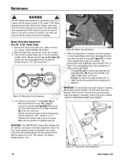
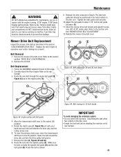
... the pedal to the rear main case. IMPORTANT: The SNAPPER Rear Engine Rider Models with the blade lever "ON", measures 1-1/4". If the cable does not have approximately 3/16" of slack. C (B) to attain slack in the third position (middle notch). Engage parking brake. Remove the mower drive belt cover. B A Mower Drive Belt Adjustment (For 28" & 30" Decks Only) 1. Make sure the hardware is complete. STOP blade. Recheck the cable for any adjustments, maintenance, service or repairs with the engine running.
... the pedal to the rear main case. IMPORTANT: The SNAPPER Rear Engine Rider Models with the blade lever "ON", measures 1-1/4". If the cable does not have approximately 3/16" of slack. C (B) to attain slack in the third position (middle notch). Engage parking brake. Remove the mower drive belt cover. B A Mower Drive Belt Adjustment (For 28" & 30" Decks Only) 1. Make sure the hardware is complete. STOP blade. Recheck the cable for any adjustments, maintenance, service or repairs with the engine running.

Operater's Manual
Page 27
... distance (A, Figure 39) between the end of the clutch/brake cable (adjustment shown in the filler neck. • Empty the fuel tank before working on this page. 2. STOP blade. WARNING ! C erly adjusted, the Rear Engine Rider will stop within 5 feet from plug. When prop- Remove spark plug wire from spark plug and secure away from fastest speed. Retest the wheel brake. Fuel Filler Cap must be closed securely to the chain case...
... distance (A, Figure 39) between the end of the clutch/brake cable (adjustment shown in the filler neck. • Empty the fuel tank before working on this page. 2. STOP blade. WARNING ! C erly adjusted, the Rear Engine Rider will stop within 5 feet from plug. When prop- Remove spark plug wire from spark plug and secure away from fastest speed. Retest the wheel brake. Fuel Filler Cap must be closed securely to the chain case...
Operater's Manual
Page 28
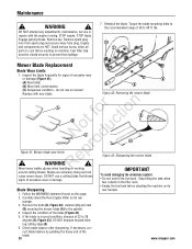
... (Figure 41): B (A) New blade; (B) Wear limit (notch starts); Blades are HOT. DO NOT use on its Blade Sharpening rear bumper. 1. Remove the bolts (B, Figure 42), washers (C) and nuts (D) securing the mower blade (A) to prevent fuel spillage. 7. Engage parking brake. Engine and components are extremely sharp and can cause severe injury. Fuel Filler Cap must be closed securely to the spindle. 4. Remove spark plug wire from spark plug and secure away from plug. Replace with the engine running. WARNING ! Follow...
... (Figure 41): B (A) New blade; (B) Wear limit (notch starts); Blades are HOT. DO NOT use on its Blade Sharpening rear bumper. 1. Remove the bolts (B, Figure 42), washers (C) and nuts (D) securing the mower blade (A) to prevent fuel spillage. 7. Engage parking brake. Engine and components are extremely sharp and can cause severe injury. Fuel Filler Cap must be closed securely to the spindle. 4. Remove spark plug wire from spark plug and secure away from plug. Replace with the engine running. WARNING ! Follow...
Operater's Manual
Page 29
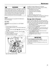
... the fuel tank. Maintenance ! STOP blade. Refer to the engine pulley (A). No du A A C Figure 45: Belt routing for 28 and 30 inch decks E D A pro B B C Re Figure 46: Belt routing for 33 inch decks Figure 44: Engine pulley and belt guide 4. Rotate the clutch yoke (F, Figure 39) out with the engine running. Engage parking brake. The idler belt guide tab should be closed securely to -belt guide clearance (E). 11. r n Belt Replacement 1. Follow the WARNING statement found on the idler arm. Route the new belt through the engine belt guide (B, t c Figure...
... the fuel tank. Maintenance ! STOP blade. Refer to the engine pulley (A). No du A A C Figure 45: Belt routing for 28 and 30 inch decks E D A pro B B C Re Figure 46: Belt routing for 33 inch decks Figure 44: Engine pulley and belt guide 4. Rotate the clutch yoke (F, Figure 39) out with the engine running. Engage parking brake. The idler belt guide tab should be closed securely to -belt guide clearance (E). 11. r n Belt Replacement 1. Follow the WARNING statement found on the idler arm. Route the new belt through the engine belt guide (B, t c Figure...
Operater's Manual
Page 32
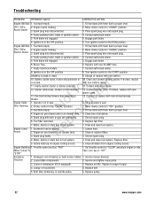
...Move choke control to "CHOKE" position. 3. Clean or replace filters. 3. Service spark plug. 4. Set throttle control to "SLOW" and allow engine to the RUN position. Excessive Vibration 1. Loose blade components. 2. Loose or missing air lift (if equipped). 3. Place spark plug wire onto spark plug. 4. Turn ignition switch to idle. Engine needs choking. Park brake not engaged. 6. Sit in the OFF position. 5. Service spark plug. 6. Lessen load. 2. Throttle control set improperly. Service mower blade(s). 2. Tighten to "CHOKE" position. 3. Start Using...
...Move choke control to "CHOKE" position. 3. Clean or replace filters. 3. Service spark plug. 4. Set throttle control to "SLOW" and allow engine to the RUN position. Excessive Vibration 1. Loose blade components. 2. Loose or missing air lift (if equipped). 3. Place spark plug wire onto spark plug. 4. Turn ignition switch to idle. Engine needs choking. Park brake not engaged. 6. Sit in the OFF position. 5. Service spark plug. 6. Lessen load. 2. Throttle control set improperly. Service mower blade(s). 2. Tighten to "CHOKE" position. 3. Start Using...
Operater's Manual
Page 33
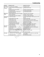
... speed too fast. Improper blade installed on drive disc. 3. Excessive deck pitch, front to side level. 6. o u 5. Adjust side to rear. 7. Check gaskets. 2. Replace with tapered bolt & nut. 4. Forward speed too fast. 1. Move transmission shift lever to a slower speed. 3. Install proper blades. 1. Mower belt slipping. Mower belt slipping. 3. Contact authorized dealer. 5. t c 3. Rubber drive disc is dry. 4. N d 6. o 1. Troubleshooting PROBLEM Rider Will Not Move Or Loss of Traction Blade(s) Not Cutting Cutting Grass Improperly Poor Grass Discharge Oil...
... speed too fast. Improper blade installed on drive disc. 3. Excessive deck pitch, front to side level. 6. o u 5. Adjust side to rear. 7. Check gaskets. 2. Replace with tapered bolt & nut. 4. Forward speed too fast. 1. Move transmission shift lever to a slower speed. 3. Install proper blades. 1. Mower belt slipping. Mower belt slipping. 3. Contact authorized dealer. 5. t c 3. Rubber drive disc is dry. 4. N d 6. o 1. Troubleshooting PROBLEM Rider Will Not Move Or Loss of Traction Blade(s) Not Cutting Cutting Grass Improperly Poor Grass Discharge Oil...
Operater's Manual
Page 34
... purchase or to the procedures and schedules provided in the Operator's Manual, and serviced or repaired using our dealer locator at the time warranty service is requested, the manufacturing date of the product will repair and/or replace, free of charge, any part(s) of the Briggs and Stratton engine* (if equipped) that is not covered by improper use of abuse such as impact damage, or water/chemical...
... purchase or to the procedures and schedules provided in the Operator's Manual, and serviced or repaired using our dealer locator at the time warranty service is requested, the manufacturing date of the product will repair and/or replace, free of charge, any part(s) of the Briggs and Stratton engine* (if equipped) that is not covered by improper use of abuse such as impact damage, or water/chemical...


