
Operater's Manual
Page 1
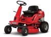
Description 7800784 2811524BV 7800785 2812524BVE 7800786 3014524BVE 7800787 3317524BVE RNeoptrfoodruction ! Manual No. 7104742 (Rev. '-') Operator's Manual REAR ENGINE RIDING MOWER SERIES 24 Model No.
Description 7800784 2811524BV 7800785 2812524BVE 7800786 3014524BVE 7800787 3317524BVE RNeoptrfoodruction ! Manual No. 7104742 (Rev. '-') Operator's Manual REAR ENGINE RIDING MOWER SERIES 24 Model No.
Operater's Manual
Page 3
... of Contents Operator Safety 4 Features and Controls 9 Operation 10 Before Starting 10 Operator Seat Adjustment 10 Starting Engine 11 Engaging Mower Blade 13 Engaging Wheel Drive 13 Stopping Engine, Wheel Drive, Blade 14 Setting Park Brake 15 Cutting Height Adjustment 15 Reverse ... Chart 17 r n General Maintenance 18 Storage 23 fo tio Engine Adjustments and Repairs 24 Mower Deck and Component Adjustments 24 Rear Engine Rider Drive Components 27 t c Mower Blade Replacement 28 o Mower Drive Belt Replacement 29 u Battery 30 N d Troubleshooting 32 ro Warranty 34 Rep Slope ...
... of Contents Operator Safety 4 Features and Controls 9 Operation 10 Before Starting 10 Operator Seat Adjustment 10 Starting Engine 11 Engaging Mower Blade 13 Engaging Wheel Drive 13 Stopping Engine, Wheel Drive, Blade 14 Setting Park Brake 15 Cutting Height Adjustment 15 Reverse ... Chart 17 r n General Maintenance 18 Storage 23 fo tio Engine Adjustments and Repairs 24 Mower Deck and Component Adjustments 24 Rear Engine Rider Drive Components 27 t c Mower Blade Replacement 28 o Mower Drive Belt Replacement 29 u Battery 30 N d Troubleshooting 32 ro Warranty 34 Rep Slope ...
Operater's Manual
Page 4
...with engine running. Use a slow speed and avoid sudden or sharp turns. DO NOT operate machine back and forth across face of mower-related injuries. 1. Practice on slopes exceeding 15 These operators should evaluate their ability to neutral (or actuate hydro roll release) and coast...shift on slopes above , are functioning properly. 12. Keep away from serious injury. washouts, culverts, fences and protruding objects. 4 www.snapper.com Children are a major factor related to loss-of children. DO NOT allow only persons who have any questions pertaining to your machine ...
...with engine running. Use a slow speed and avoid sudden or sharp turns. DO NOT operate machine back and forth across face of mower-related injuries. 1. Practice on slopes exceeding 15 These operators should evaluate their ability to neutral (or actuate hydro roll release) and coast...shift on slopes above , are functioning properly. 12. Keep away from serious injury. washouts, culverts, fences and protruding objects. 4 www.snapper.com Children are a major factor related to loss-of children. DO NOT allow only persons who have any questions pertaining to your machine ...
Operater's Manual
Page 5
... machine unless properly seated with the rim of control. STOP BLADES and ENGINE and make sure blades have a dust mask, long pants and substantial footwear. mower to STOP blades and engine quickly in handling gasoline. spots. Always place the contain- Remove gas-powered equipment from rotating blades under- DO NOT operate...
... machine unless properly seated with the rim of control. STOP BLADES and ENGINE and make sure blades have a dust mask, long pants and substantial footwear. mower to STOP blades and engine quickly in handling gasoline. spots. Always place the contain- Remove gas-powered equipment from rotating blades under- DO NOT operate...
Operater's Manual
Page 6
...serviced by grounding spark plug next to spark plug hole; Use only factory authorized replacement parts or like parts when making repairs. 6 www.snapper.com Tow only with a machine that RNeoptroduc all bolts, nuts and screws properly tight. Exhaust gases contain carbon monoxide, an odor- ...NOT allow extra distance to dling them. Travel slowly and allow children or others on slopes. 7. in a well ventilated, unoccupied building. Mower blades are in an prevent controls from battery before storing machine in proper position. 13. When draining fuel tank, drain fuel into an ...
...serviced by grounding spark plug next to spark plug hole; Use only factory authorized replacement parts or like parts when making repairs. 6 www.snapper.com Tow only with a machine that RNeoptroduc all bolts, nuts and screws properly tight. Exhaust gases contain carbon monoxide, an odor- ...NOT allow extra distance to dling them. Travel slowly and allow children or others on slopes. 7. in a well ventilated, unoccupied building. Mower blades are in an prevent controls from battery before storing machine in proper position. 13. When draining fuel tank, drain fuel into an ...
Operater's Manual
Page 7
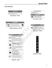
... relating to fire prevention requirements. 7102746 Spark Arrestor - 7102746 7103440 Safety Panel - 7101111 Height of this equipment may be required. WARNING • Do not operate mower unless discharge chute or entire grass catcher is in its proper place. 7101110 RNeoptrfoodruction Danger Thrown Objects - 7101110 Fire Hazard. Operation of Cut - 703440 7 A spark...
... relating to fire prevention requirements. 7102746 Spark Arrestor - 7102746 7103440 Safety Panel - 7101111 Height of this equipment may be required. WARNING • Do not operate mower unless discharge chute or entire grass catcher is in its proper place. 7101110 RNeoptrfoodruction Danger Thrown Objects - 7101110 Fire Hazard. Operation of Cut - 703440 7 A spark...
Operater's Manual
Page 13
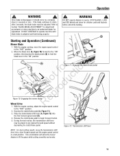
... 1. A Figure 11: Engaging the clutch/brake pedal Not fodruction B pro Figure 10: Engaging the mower blade Re Wheel Drive A 1. If the blade continues to rotate after 3 seconds, the blade brake must be placed in 3 seconds or less.... hazards before and while backing. With the engine running , move the transmission shift lever into the first forward speed notch (B). 4. This combination will allow the mower blades to begin forward motion. 5. Refer to Section "BLADE BRAKE ADJUSTMENT" for adjustment procedures or return machine to the "FAST" position. 2. B 3. Once...
... 1. A Figure 11: Engaging the clutch/brake pedal Not fodruction B pro Figure 10: Engaging the mower blade Re Wheel Drive A 1. If the blade continues to rotate after 3 seconds, the blade brake must be placed in 3 seconds or less.... hazards before and while backing. With the engine running , move the transmission shift lever into the first forward speed notch (B). 4. This combination will allow the mower blades to begin forward motion. 5. Refer to Section "BLADE BRAKE ADJUSTMENT" for adjustment procedures or return machine to the "FAST" position. 2. B 3. Once...
Operater's Manual
Page 14
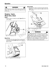
..."BLADE BRAKE ADJUSTMENT" for adjustment. Shift to an authorized dealer for adjustment procedures or return machine to neutral and engage park brake. Stop the mower blade by releasing the blade pedals (A, Figure 15) or moving the blade lever (B) rearward to the "OFF" position. RepA Figure 14: ...Engaging the clutch/brake pedal 14 www.snapper.com Stop the engine by pushing the o clutch/brake pedal (A, Figure 14) all the way down to r apply the brake. DO NOT CONTINUE to...
..."BLADE BRAKE ADJUSTMENT" for adjustment. Shift to an authorized dealer for adjustment procedures or return machine to neutral and engage park brake. Stop the mower blade by releasing the blade pedals (A, Figure 15) or moving the blade lever (B) rearward to the "OFF" position. RepA Figure 14: ...Engaging the clutch/brake pedal 14 www.snapper.com Stop the engine by pushing the o clutch/brake pedal (A, Figure 14) all the way down to r apply the brake. DO NOT CONTINUE to...
Operater's Manual
Page 16
...oper- r n We realize that this new fo tio system. This feature should o never be selected unless you operate your local Snapper dealer for proper ate blades in reverse. DO NOT operate machine if Reverse Lockout Mechanism is our recommendation that this could cause a change...release blade pedals to "ON" position. If you are present in yard when mowing. 16 www.snapper.com Operation Reverse Lockout Mechanism Reverse Lockout Mechanism Override 1. This riding mower has a Reverse Lockout Mechanism. Data indicates that no chilr dren or others are absolutely sure that ...
...oper- r n We realize that this new fo tio system. This feature should o never be selected unless you operate your local Snapper dealer for proper ate blades in reverse. DO NOT operate machine if Reverse Lockout Mechanism is our recommendation that this could cause a change...release blade pedals to "ON" position. If you are present in yard when mowing. 16 www.snapper.com Operation Reverse Lockout Mechanism Reverse Lockout Mechanism Override 1. This riding mower has a Reverse Lockout Mechanism. Data indicates that no chilr dren or others are absolutely sure that ...

Operater's Manual
Page 17
...Annually * Every 25 Hours or Annually * Check tire pressure Clean engine air filter and pre-cleaner ** Check mower blade stopping time Every 50 Hours or Annually * Check tractor/mower for loose hardware Change engine oil Every 50 Hours or Annually * Replace oil filter Clean battery and cables ...or when airborne debris is present. 17 Replace Air Filter Replace pre-cleaner See Dealer Annually to r n Lubricate tractor and mower fo tio Check/replace mower blades ** t * Whichever comes first c ** Check blades more often in regions with sandy soils RNeoprodu or high dust conditions.
...Annually * Every 25 Hours or Annually * Check tire pressure Clean engine air filter and pre-cleaner ** Check mower blade stopping time Every 50 Hours or Annually * Check tractor/mower for loose hardware Change engine oil Every 50 Hours or Annually * Replace oil filter Clean battery and cables ...or when airborne debris is present. 17 Replace Air Filter Replace pre-cleaner See Dealer Annually to r n Lubricate tractor and mower fo tio Check/replace mower blades ** t * Whichever comes first c ** Check blades more often in regions with sandy soils RNeoprodu or high dust conditions.
Operater's Manual
Page 18
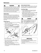
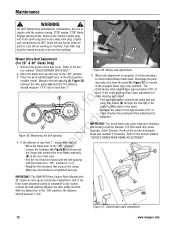
... on machine. the Engine Manual for sharpness, wear and damage. Remove key. Carefully stand the Rear Engine Rider on the engine. 3. entitled "ADJUSTING MOWER BLADE". DANGER ! Loosen or remove the oil fill cap on the rear bumper. (See statement below.) 3. pro A Re Figure 20: Checking blade... wooden blocks under the end of the engine. Change the oil filter on its rear bumper. 18 www.snapper.com As necessary, torque to 30 to the section Riding Mower, always mention the model and serial number. fo tio 2. Maintenance ! We recommend returning the Rear Engine ...
... on machine. the Engine Manual for sharpness, wear and damage. Remove key. Carefully stand the Rear Engine Rider on the engine. 3. entitled "ADJUSTING MOWER BLADE". DANGER ! Loosen or remove the oil fill cap on the rear bumper. (See statement below.) 3. pro A Re Figure 20: Checking blade... wooden blocks under the end of the engine. Change the oil filter on its rear bumper. 18 www.snapper.com As necessary, torque to 30 to the section Riding Mower, always mention the model and serial number. fo tio 2. Maintenance ! We recommend returning the Rear Engine ...
Operater's Manual
Page 19
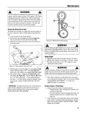
...position and depress the blade pedals. 5. 28" and 30" Decks *: Measure the belt spacing at the R idler pulley (A, Figure 22). SNAPPER dealer for proper function. STOP engine. Remove spark plug wire from spark plug and secure away from the engine to cool before operating the ...Brake 1. Engine and components are not functioning properly, brake adjustment must stop rotating in less than 5 ft. 2. Inspect for signs of mower drive belt cover (B). 3. for proper function: Engage the park brake, and push the machine. Clear area of Figure 22: Measuring the belt spacing...
...position and depress the blade pedals. 5. 28" and 30" Decks *: Measure the belt spacing at the R idler pulley (A, Figure 22). SNAPPER dealer for proper function. STOP engine. Remove spark plug wire from spark plug and secure away from the engine to cool before operating the ...Brake 1. Engine and components are not functioning properly, brake adjustment must stop rotating in less than 5 ft. 2. Inspect for signs of mower drive belt cover (B). 3. for proper function: Engage the park brake, and push the machine. Clear area of Figure 22: Measuring the belt spacing...
Operater's Manual
Page 20
...lever must be completely grease gun. ep Lubrication - Engage the latch over the cover and rotate and push down to the section entitled "MOWER BLADE SPINDLE - LUBRICATION". 3. Refer to lock. The Clutch/Brake Pedal is in the "ON" (blades engaged) posi- WARNING !... The Blade Control is not in "ON" (blades engaged) position OR, 2. WARNING ! DO NOT operate machine if any safety device. Contact your SNAPPER dealer immediately for inspection. Refer to defeat, modify or remove any safety interlock or safety device is in the "OFF" (blades disengaged) A position ...
...lever must be completely grease gun. ep Lubrication - Engage the latch over the cover and rotate and push down to the section entitled "MOWER BLADE SPINDLE - LUBRICATION". 3. Refer to lock. The Clutch/Brake Pedal is in the "ON" (blades engaged) posi- WARNING !... The Blade Control is not in "ON" (blades engaged) position OR, 2. WARNING ! DO NOT operate machine if any safety device. Contact your SNAPPER dealer immediately for inspection. Refer to defeat, modify or remove any safety interlock or safety device is in the "OFF" (blades disengaged) A position ...
Operater's Manual
Page 21
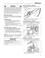
...tank before working on machine. A Figure 26: Shift lever grease fitting 21 STOP blade. Clean the underside of grass clippings and debris. Mower Blade Spindle - Lubrication t c 1. Follow the WARNING statement found on its rear bumper for proper level. Re IMPORTANT Lubricate the front... from spark plug and secure away from a grease gun. Refer to the Section entitled "BATTERY REMOVAL". Refer to the section entitled "MOWER DECK ADJUSTMENT - STOP engine. Lubrication Lubricate all parts to prevent fuel spillage. LEVELNESS". r n 5. ro IMPORTANT: If the unit will...
...tank before working on machine. A Figure 26: Shift lever grease fitting 21 STOP blade. Clean the underside of grass clippings and debris. Mower Blade Spindle - Lubrication t c 1. Follow the WARNING statement found on its rear bumper for proper level. Re IMPORTANT Lubricate the front... from spark plug and secure away from a grease gun. Refer to the Section entitled "BATTERY REMOVAL". Refer to the section entitled "MOWER DECK ADJUSTMENT - STOP engine. Lubrication Lubricate all parts to prevent fuel spillage. LEVELNESS". r n 5. ro IMPORTANT: If the unit will...
Operater's Manual
Page 23
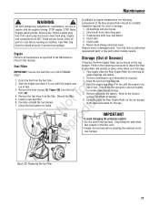
... fuel filter. STOP blade. Refer to remain clean during storage. 5. Maintenance ! Remove spark plug wire from spark plug and secure away from the fuel tank. 4. Mower deck linkage and pivot areas. Carefully reinstall the fuel clamps. 7. Remove and store the battery. Remove the hose clamps (B, Figure 30) from the fuel fo...
... fuel filter. STOP blade. Refer to remain clean during storage. 5. Maintenance ! Remove spark plug wire from spark plug and secure away from the fuel tank. 4. Mower deck linkage and pivot areas. Carefully reinstall the fuel clamps. 7. Remove and store the battery. Remove the hose clamps (B, Figure 30) from the fuel fo...
Operater's Manual
Page 24
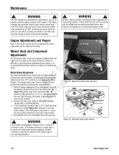
...tension. 4. e 2. If the dimension is less than 3", rotate the nut counter-clockwise to an authorized Snapper dealer. If the dimension is greater than 3 seconds to a stop , N d perform the following mower deck and component adjustments and repairs can be adjusted. B - ! Remove spark plug wire from spark ... between the front of the blade lever (A, r Figure 31) and the edge of the plate. Figure 32: Adjusting blade brake tension 24 www.snapper.com If the dimension is r n recommended that can be 3" to prevent fuel spillage. ! STOP blade. However, if there is difficulty in...
...tension. 4. e 2. If the dimension is less than 3", rotate the nut counter-clockwise to an authorized Snapper dealer. If the dimension is greater than 3 seconds to a stop , N d perform the following mower deck and component adjustments and repairs can be adjusted. B - ! Remove spark plug wire from spark ... between the front of the blade lever (A, r Figure 31) and the edge of the plate. Figure 32: Adjusting blade brake tension 24 www.snapper.com If the dimension is r n recommended that can be 3" to prevent fuel spillage. ! STOP blade. However, if there is difficulty in...
Operater's Manual
Page 25
...the front, proceed with adjustment. rear 1/8" to - Reinstall the rear hanger chains and measure the blade tips again. 4. Maintenance ! WARNING 10. Mower Deck Adjustment (Front-to rear levelness. Remove spark plug wire from spark plug and secure away from the blade tips to 1/4" lower than the ...front. Engine and components are at the front and rear 1. Fuel Filler Cap must be the same, or the Mower Deck Adjustment (Side-To-Side Levelness) Before making deck leveling adjustments, check the tire rear 1/8" to the 2. The distance should be the...
...the front, proceed with adjustment. rear 1/8" to - Reinstall the rear hanger chains and measure the blade tips again. 4. Maintenance ! WARNING 10. Mower Deck Adjustment (Front-to rear levelness. Remove spark plug wire from spark plug and secure away from the blade tips to 1/4" lower than the ...front. Engine and components are at the front and rear 1. Fuel Filler Cap must be the same, or the Mower Deck Adjustment (Side-To-Side Levelness) Before making deck leveling adjustments, check the tire rear 1/8" to the 2. The distance should be the...
Operater's Manual
Page 26
...section entitled "SERVICE BRAKE/PARK BRAKE ADJUSTMENT". The clutch/brake cable should measure 1-3/4". Refer to the "OFF" position. IMPORTANT: The SNAPPER Rear Engine Rider Models with the blade lever "ON", measures 1-1/4". With the blade lever in the "ON" position, the distance ... Too much slack may cause improper clutch function. Avoid serious burns, allow the pedal (A, Figure 37) to check Clutch/Brake Cable slack. B A Mower Drive Belt Adjustment (For 28" & 30" Decks Only) 1. C (B) to prevent fuel spillage. Maintenance ! WARNING ! Fuel Filler Cap must be...
...section entitled "SERVICE BRAKE/PARK BRAKE ADJUSTMENT". The clutch/brake cable should measure 1-3/4". Refer to the "OFF" position. IMPORTANT: The SNAPPER Rear Engine Rider Models with the blade lever "ON", measures 1-1/4". With the blade lever in the "ON" position, the distance ... Too much slack may cause improper clutch function. Avoid serious burns, allow the pedal (A, Figure 37) to check Clutch/Brake Cable slack. B A Mower Drive Belt Adjustment (For 28" & 30" Decks Only) 1. C (B) to prevent fuel spillage. Maintenance ! WARNING ! Fuel Filler Cap must be...
Operater's Manual
Page 28
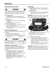
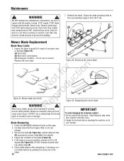
... the fuel tank. Inspect the blade frequently for signs of the blade. 28 www.snapper.com Blades are HOT. ing cutting edge (A). 6. Avoid serious burns, allow all parts to 28 degrees (B, Figure 43). ot foruction A B C N rod Figure 41: Mower blade wear limits ep ! Carefully stand the Rear Engine Rider on its rear...
... the fuel tank. Inspect the blade frequently for signs of the blade. 28 www.snapper.com Blades are HOT. ing cutting edge (A). 6. Avoid serious burns, allow all parts to 28 degrees (B, Figure 43). ot foruction A B C N rod Figure 41: Mower blade wear limits ep ! Carefully stand the Rear Engine Rider on its rear...
Operater's Manual
Page 29
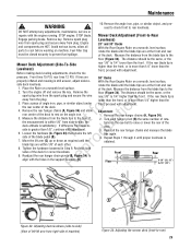
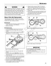
... system: • Do not overfill the fuel tank. STOP engine. Avoid serious burns, allow 1/16" belt-to the Section entitled "MOWER DRIVE BELT ADJUSTMENT". 12. Remove the old belt. Follow the WARNING statement found on machine. Route the belt onto the spindle pulley (C)....BELT". Adjust the belt guide to allow all parts to prevent fuel spillage. 9. Refer to -belt guide clearance (E). 11. Reinstall the mower drive belt cover. Mower Drive Belt Replacement Inspect the mower drive belt as shown. No du A A C Figure 45: Belt routing for 28 and 30 inch decks E D A pro ...
... system: • Do not overfill the fuel tank. STOP engine. Avoid serious burns, allow 1/16" belt-to the Section entitled "MOWER DRIVE BELT ADJUSTMENT". 12. Remove the old belt. Follow the WARNING statement found on machine. Route the belt onto the spindle pulley (C)....BELT". Adjust the belt guide to allow all parts to prevent fuel spillage. 9. Refer to -belt guide clearance (E). 11. Reinstall the mower drive belt cover. Mower Drive Belt Replacement Inspect the mower drive belt as shown. No du A A C Figure 45: Belt routing for 28 and 30 inch decks E D A pro ...


