Operater's Manual
Page 3
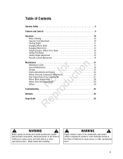
... 18 Storage 23 fo tio Engine Adjustments and Repairs 24 Mower Deck and Component Adjustments 24 Rear Engine Rider Drive Components 27 t c Mower Blade Replacement 28 o Mower Drive Belt Replacement 29 u Battery 30 N d Troubleshooting 32 ro Warranty 34 Rep Slope Guide 35 !
... 18 Storage 23 fo tio Engine Adjustments and Repairs 24 Mower Deck and Component Adjustments 24 Rear Engine Rider Drive Components 27 t c Mower Blade Replacement 28 o Mower Drive Belt Replacement 29 u Battery 30 N d Troubleshooting 32 ro Warranty 34 Rep Slope Guide 35 !
Operater's Manual
Page 19
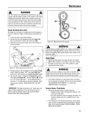
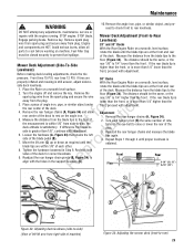
... forward and apply the brake. Engage parking brake. Avoid serious burns, allow all B parts to the "ON" position and depress the blade pedals. 5. 28" and 30" Decks *: Measure the belt spacing at the R idler pulley (A, Figure 22). sion. 1. Remove the four self-tapping screws (A, Figure ... come to the 3rd height of loose parts & tools first. WARNING ! Blade Brake 1. WARNING ! "BLADE BRAKE ADJUSTMENT", or contact your MENT". SNAPPER dealer for proper function: Engage the park brake, and push the machine. Refer to the section entitled "BLADE DRIVE BELT ADJUST- STOP blade. Lower...
... forward and apply the brake. Engage parking brake. Avoid serious burns, allow all B parts to the "ON" position and depress the blade pedals. 5. 28" and 30" Decks *: Measure the belt spacing at the R idler pulley (A, Figure 22). sion. 1. Remove the four self-tapping screws (A, Figure ... come to the 3rd height of loose parts & tools first. WARNING ! Blade Brake 1. WARNING ! "BLADE BRAKE ADJUSTMENT", or contact your MENT". SNAPPER dealer for proper function: Engage the park brake, and push the machine. Refer to the section entitled "BLADE DRIVE BELT ADJUST- STOP blade. Lower...
Operater's Manual
Page 22
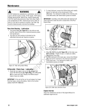
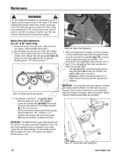
...away from grease gun. 2. Check the fill/level plug (A, Figure 29) on its rear bumper and check the fill/level plug (A, Figure 28) on the left rear axle A bearing requires three shots of general purpose grease from plug. WARNING ! If no lubricant is visible, add ... check lubricant in the chain case, remove the fill/level plug and look for additional engine service. 22 www.snapper.com Replace the fill/level plug if Figure 28: Differential lubricant check 3. Refer to cool before working on the internal parts of the differential. The right rear axle...
...away from grease gun. 2. Check the fill/level plug (A, Figure 29) on its rear bumper and check the fill/level plug (A, Figure 28) on the left rear axle A bearing requires three shots of general purpose grease from plug. WARNING ! If no lubricant is visible, add ... check lubricant in the chain case, remove the fill/level plug and look for additional engine service. 22 www.snapper.com Replace the fill/level plug if Figure 28: Differential lubricant check 3. Refer to cool before working on the internal parts of the differential. The right rear axle...
Operater's Manual
Page 25
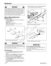
...Figure 33) that retains the left lift arm from the plug. 3. rear 1/8" to rear levelness. Remove the rear hanger chains (A, Figure 34). 2. Front Floor X Rear X-1/8" (28, 33") X+1/8" (30") B B A C C Figure 33: Adjusting deck levelness (side-to-side) (View of left N d side of machine) D A Figure 34: ...tires 15 PSI, rear tires 12 PSI. Tighten the hardware loosened in the support brackets (D). Recheck both sides of the deck. Levelness) 28" and 33" Decks With the Rear Engine Rider on the angle iron. 5. pressure. Remove the rear hanger chains (A, Figure 34) and...
...Figure 33) that retains the left lift arm from the plug. 3. rear 1/8" to rear levelness. Remove the rear hanger chains (A, Figure 34). 2. Front Floor X Rear X-1/8" (28, 33") X+1/8" (30") B B A C C Figure 33: Adjusting deck levelness (side-to-side) (View of left N d side of machine) D A Figure 34: ...tires 15 PSI, rear tires 12 PSI. Tighten the hardware loosened in the support brackets (D). Recheck both sides of the deck. Levelness) 28" and 33" Decks With the Rear Engine Rider on the angle iron. 5. pressure. Remove the rear hanger chains (A, Figure 34) and...
Operater's Manual
Page 26
... distance should measure 1-3/4". If the distance is loosened for the approximate 3/16" of slack. C (B) to the "OFF" position. IMPORTANT: The SNAPPER Rear Engine Rider Models with 33" decks do not require belt tension adjustment. Figure 37: Clutch/brake cable adjustment 26 www...the cable does not have approximately 3/16" of cable must be necessary to cool before working on machine. B A Mower Drive Belt Adjustment (For 28" & 30" Decks Only) 1. Remove the mower drive belt cover. Engine and components are HOT. Replace the pedal pad when adjustment is tightened securely...
... distance should measure 1-3/4". If the distance is loosened for the approximate 3/16" of slack. C (B) to the "OFF" position. IMPORTANT: The SNAPPER Rear Engine Rider Models with 33" decks do not require belt tension adjustment. Figure 37: Clutch/brake cable adjustment 26 www...the cable does not have approximately 3/16" of cable must be necessary to cool before working on machine. B A Mower Drive Belt Adjustment (For 28" & 30" Decks Only) 1. Remove the mower drive belt cover. Engine and components are HOT. Replace the pedal pad when adjustment is tightened securely...
Operater's Manual
Page 28
... ft. A (C) Dangerous condition - Check blade balance after sharpening. Remove key. Avoid serious burns, allow all parts to 28 degrees (B, Figure 43). Follow the WARNING statement found on machine. Inspect the condition of the blade. 28 www.snapper.com lbs. WARNING ! STOP blade. ot foruction A B C N rod Figure 41: Mower blade wear limits ep ! Stop...
... ft. A (C) Dangerous condition - Check blade balance after sharpening. Remove key. Avoid serious burns, allow all parts to 28 degrees (B, Figure 43). Follow the WARNING statement found on machine. Inspect the condition of the blade. 28 www.snapper.com lbs. WARNING ! STOP blade. ot foruction A B C N rod Figure 41: Mower blade wear limits ep ! Stop...
Operater's Manual
Page 29
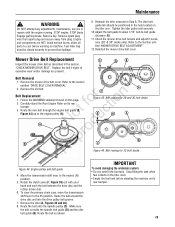
... belt guide to allow all parts to the section entitled "DRIVE BELT COVER REMOVAL". 2. Check the mower drive belt tension and adjust if necessary (28" & 30" decks only). Route the belt onto the spindle pulley (C). Remove the mower drive belt cover. No du A A C Figure 45: Belt routing ...for 28 and 30 inch decks E D A pro B B C Re Figure 46: Belt routing for 33 inch decks Figure 44: Engine pulley and belt guide 4. Maintenance ! Tighten the...
... belt guide to allow all parts to the section entitled "DRIVE BELT COVER REMOVAL". 2. Check the mower drive belt tension and adjust if necessary (28" & 30" decks only). Route the belt onto the spindle pulley (C). Remove the mower drive belt cover. No du A A C Figure 45: Belt routing ...for 28 and 30 inch decks E D A pro B B C Re Figure 46: Belt routing for 33 inch decks Figure 44: Engine pulley and belt guide 4. Maintenance ! Tighten the...
Operater's Manual
Page 36
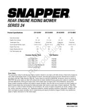
...at 3600 RPM. tude), and engine-to , the variety of engine components (air cleaner, exhaust, charg- www.snapper.com Due to -engine variability. Net power values are taken with exhaust and air cleaner installed whereas gross power ...pump, etc.), application limitations, ambient operating conditions (temperature, humidity, alti- REAR ENGINE RIDING MOWER SERIES 24 Product Specifications 2811524BV 2812524BVE 3014524BVE 3317524BVE Deck Size (inches) 28 28 30 33 Height of Cut (inches) 1.5 - 4.0 1.5 - 4.0 1.5 - 4.0 1.5 - 4.0 Transmission Type Ground Speed-Fwd/Rev (mph) r n ...
...at 3600 RPM. tude), and engine-to , the variety of engine components (air cleaner, exhaust, charg- www.snapper.com Due to -engine variability. Net power values are taken with exhaust and air cleaner installed whereas gross power ...pump, etc.), application limitations, ambient operating conditions (temperature, humidity, alti- REAR ENGINE RIDING MOWER SERIES 24 Product Specifications 2811524BV 2812524BVE 3014524BVE 3317524BVE Deck Size (inches) 28 28 30 33 Height of Cut (inches) 1.5 - 4.0 1.5 - 4.0 1.5 - 4.0 1.5 - 4.0 Transmission Type Ground Speed-Fwd/Rev (mph) r n ...