Operating Instructions
Page 2
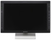
... is intended for use for parts of the unit on which this symbol appears. Refer servicing to the bar code representation of the Unique...open the cabinet. Indications for Use/Intended Use The Sony LMD-2451MT LCD Monitor is intended to provide 3D and 2D color video displays of images from surgical endoscopic/laparoscopic camera systems and other compatible medical imaging systems. The LMD-2451MT is a widescreen, high-definition, medical grade monitor for real-time use during operation of the unit, operate the disconnect device to switch the power supply off, or disconnect the power plug...
... is intended for use for parts of the unit on which this symbol appears. Refer servicing to the bar code representation of the Unique...open the cabinet. Indications for Use/Intended Use The Sony LMD-2451MT LCD Monitor is intended to provide 3D and 2D color video displays of images from surgical endoscopic/laparoscopic camera systems and other compatible medical imaging systems. The LMD-2451MT is a widescreen, high-definition, medical grade monitor for real-time use during operation of the unit, operate the disconnect device to switch the power supply off, or disconnect the power plug...

Operating Instructions
Page 8
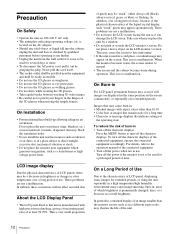
.... 8 Otherwise, degradation of the performance of each country if applicable. 2. Use the approved Power Cord (3-core mains lead) / Appliance Connector / Plug with earthing-contacts that conforms to the proper ratings (Voltage, Ampere). Portable RF communications equipment should use the following type of the LMD-2451MT. and Canada should use the power cord prescribed by absorption and reflection from RF wireless communications equipment...
.... 8 Otherwise, degradation of the performance of each country if applicable. 2. Use the approved Power Cord (3-core mains lead) / Appliance Connector / Plug with earthing-contacts that conforms to the proper ratings (Voltage, Ampere). Portable RF communications equipment should use the following type of the LMD-2451MT. and Canada should use the power cord prescribed by absorption and reflection from RF wireless communications equipment...
Operating Instructions
Page 11
... Parts and Controls 18 Front Panel 18 Input Signals and Adjustable/Setting Items ..... 20 Rear/Bottom Panel 22 Connecting the AC Power Cord 24 Installing the Input Adaptor 25 Attaching the Provided L/R Labels 25 Removing the Connector Cover 26 Selecting the Default Settings 26 Selecting the Menu Language 28 Using the Menu 29 Loading USER MEMORY 30 Adjustment Using the Menus 31 Items 31 Adjusting and Changing the Settings 32 STATUS menu 32 COLOR TEMP/SPACE menu 32 USER CONTROL menu 33 USER CONFIG menu 35 REMOTE menu...
... Parts and Controls 18 Front Panel 18 Input Signals and Adjustable/Setting Items ..... 20 Rear/Bottom Panel 22 Connecting the AC Power Cord 24 Installing the Input Adaptor 25 Attaching the Provided L/R Labels 25 Removing the Connector Cover 26 Selecting the Default Settings 26 Selecting the Menu Language 28 Using the Menu 29 Loading USER MEMORY 30 Adjustment Using the Menus 31 Items 31 Adjusting and Changing the Settings 32 STATUS menu 32 COLOR TEMP/SPACE menu 32 USER CONTROL menu 33 USER CONFIG menu 35 REMOTE menu...
Operating Instructions
Page 12
... LCD Display Panel • The LCD panel fitted to pinch your fingers in use the 3D glasses as in color temperature over a long period of use , because of the physical characteristics of LCD panel, displaying static images for several days or more. • To disconnect the AC power cord, pull it out by grasping the plug. This is manufactured with aspect ratios other than the monitor screen...
... LCD Display Panel • The LCD panel fitted to pinch your fingers in use the 3D glasses as in color temperature over a long period of use , because of the physical characteristics of LCD panel, displaying static images for several days or more. • To disconnect the AC power cord, pull it out by grasping the plug. This is manufactured with aspect ratios other than the monitor screen...
Operating Instructions
Page 13
... the front panel blinks for fan error indication, turn off the power and contact an authorized Sony dealer. Laying down or looking away from a cold to a warm location, or if ambient temperature suddenly rises, moisture may be removed with a soft...power cord from the AC outlet. This is used for the protection plate surface/monitor surface, the performance of the monitor may be impaired or the finish of 3D glasses while holding or transporting. • Avoid wearing the 3D glasses when they will lessen the 3D effect or shifts image colors. When solvents such as a cleaning cloth lightly...
... the front panel blinks for fan error indication, turn off the power and contact an authorized Sony dealer. Laying down or looking away from a cold to a warm location, or if ambient temperature suddenly rises, moisture may be removed with a soft...power cord from the AC outlet. This is used for the protection plate surface/monitor surface, the performance of the monitor may be impaired or the finish of 3D glasses while holding or transporting. • Avoid wearing the 3D glasses when they will lessen the 3D effect or shifts image colors. When solvents such as a cleaning cloth lightly...
Operating Instructions
Page 15
... 3D monitor display mode. Liquid crystal and color filters are in a grid pattern. This function is displayed. This helps you to easily compare the color and brightness between left and right signals are displayed in front of flat light source (backlight) on the front of the determined screen position or behind it. While multi-signal formats, including 1080P, 1080i, 1080PsF and 720P, are available, line-by controlling the...
... 3D monitor display mode. Liquid crystal and color filters are in a grid pattern. This function is displayed. This helps you to easily compare the color and brightness between left and right signals are displayed in front of flat light source (backlight) on the front of the determined screen position or behind it. While multi-signal formats, including 1080P, 1080i, 1080PsF and 720P, are available, line-by controlling the...
Operating Instructions
Page 16
... the board to the appropriate setting in "USER". Two-display Two kinds of input signals are output to the output connector (loop-through). By adjusting the color temperature/space settings for the display from an external sync generator. Accepts DVI-D (digital) input signals Adopting the scan converter allows this monitor to detect VGA, SVGA, XGA and SXGA analog RGB signals input to view an image, and so on.). Optional port Two optional input adaptors can be saved...
... the board to the appropriate setting in "USER". Two-display Two kinds of input signals are output to the output connector (loop-through). By adjusting the color temperature/space settings for the display from an external sync generator. Accepts DVI-D (digital) input signals Adopting the scan converter allows this monitor to detect VGA, SVGA, XGA and SXGA analog RGB signals input to view an image, and so on.). Optional port Two optional input adaptors can be saved...
Operating Instructions
Page 18
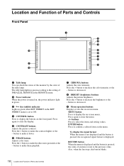
... display the buttons on -screen menu. d CONTROL button Press to ON. button to increase the brightness or the - The tally lamp lights in green according to make the skin tones greenish or the - e CONTRAST buttons Adjusts the picture contrast. button to the setting of an item is turned on -screen menu. Press the + button to make the contrast higher or the - button to make it lower. i Menu operation buttons Displays or sets the on , the power indicator light in the REMOTE menu. Press the + button...
... display the buttons on -screen menu. d CONTROL button Press to ON. button to increase the brightness or the - The tally lamp lights in green according to make the skin tones greenish or the - e CONTRAST buttons Adjusts the picture contrast. button to the setting of an item is turned on -screen menu. Press the + button to make the contrast higher or the - button to make it lower. i Menu operation buttons Displays or sets the on , the power indicator light in the REMOTE menu. Press the + button...
Operating Instructions
Page 19
... SYNC, BLUE ONLY, MONO, MULTI DISPLAY, APA, I/P MODE, MIRROR IMAGE, 2D/3D SELECT, L/R SWITCH, DISPARITY SIM., etc., in FUNCTION BUTTON SETTING of the USER CONFIG menu (see page 37. j Input select buttons Press the button to monitor the signal input to the function button, see page 37). A-1, A-2, B-1 and B-2 buttons are used when an optional input adaptor has been installed in the option port. COMPOSITE button: to monitor the signal through the COMPOSITE IN connector Y/C button: to monitor the signal...
... SYNC, BLUE ONLY, MONO, MULTI DISPLAY, APA, I/P MODE, MIRROR IMAGE, 2D/3D SELECT, L/R SWITCH, DISPARITY SIM., etc., in FUNCTION BUTTON SETTING of the USER CONFIG menu (see page 37. j Input select buttons Press the button to monitor the signal input to the function button, see page 37). A-1, A-2, B-1 and B-2 buttons are used when an optional input adaptor has been installed in the option port. COMPOSITE button: to monitor the signal through the COMPOSITE IN connector Y/C button: to monitor the signal...
Operating Instructions
Page 20
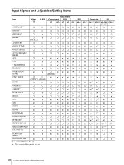
Input Signals and Adjustable/Setting Items Item CONTRAST*1 Video, Y/C a B & W a Input signal Component SD HD RGB SDI Computer 3D SD HD SD*3 HD*3 3G*11 DVI*10 HD15 HD-SDI DVI*12 *11, *12 a aaa a a a a a a a BRIGHT*1 a a a aaa a a a a a a a CHROMA*1 PHASE*1 a × a × (NTSC) a aaa a a a a a a a a aaa a a a a a a a APERTURE a a a aaa a a a a a a a COLOR TEMP a a a aaa a a a a a a a COLOR SPACE a a a aaa a a a a a a a AUTO CHROMA/ a × a a PHASE ACC a × CTI a × a V SHARPNESS a a a ×a× a MATRIX*2 &#...
Input Signals and Adjustable/Setting Items Item CONTRAST*1 Video, Y/C a B & W a Input signal Component SD HD RGB SDI Computer 3D SD HD SD*3 HD*3 3G*11 DVI*10 HD15 HD-SDI DVI*12 *11, *12 a aaa a a a a a a a BRIGHT*1 a a a aaa a a a a a a a CHROMA*1 PHASE*1 a × a × (NTSC) a aaa a a a a a a a a aaa a a a a a a a APERTURE a a a aaa a a a a a a a COLOR TEMP a a a aaa a a a a a a a COLOR SPACE a a a aaa a a a a a a a AUTO CHROMA/ a × a a PHASE ACC a × CTI a × a V SHARPNESS a a a ×a× a MATRIX*2 &#...
Operating Instructions
Page 22
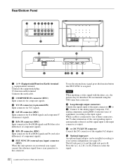
... earth cable. To use the external sync signal, press the function button that EXT SYNC is B. d G/Y IN connector (BNC) Input connector for G of equipment, according to the analog input (composite, Y/C, analog component, analog RGB or external sync) of RGB signals and component Y (luminance) signals. g EXT SYNC IN (external sync input) connector (BNC) When this unit operates on an external sync signal, connect the reference signal from a sync generator to 7). We recommend using the TBC (time base corrector). Connect to the input signal...
... earth cable. To use the external sync signal, press the function button that EXT SYNC is B. d G/Y IN connector (BNC) Input connector for G of equipment, according to the analog input (composite, Y/C, analog component, analog RGB or external sync) of RGB signals and component Y (luminance) signals. g EXT SYNC IN (external sync input) connector (BNC) When this unit operates on an external sync signal, connect the reference signal from a sync generator to 7). We recommend using the TBC (time base corrector). Connect to the input signal...
Operating Instructions
Page 23
...) Inputs an analog RGB video signal (0.7 Vp-p, positive polarity) and sync signal. To view the signals of the SXGA and higher resolution when the DVI input is attached to control commands sent from the factory, a connector cover is selected, use of 10BASE-T/ 100BASE-TX. When the unit is shipped from external equipment connected to this connector and patients at the same time. Always disconnect the power cord before using a 10BASE-T/ 100BASE-TX LAN cable...
...) Inputs an analog RGB video signal (0.7 Vp-p, positive polarity) and sync signal. To view the signals of the SXGA and higher resolution when the DVI input is attached to control commands sent from the factory, a connector cover is selected, use of 10BASE-T/ 100BASE-TX. When the unit is shipped from external equipment connected to this connector and patients at the same time. Always disconnect the power cord before using a 10BASE-T/ 100BASE-TX LAN cable...

Operating Instructions
Page 32
... input STATUS 1/2 F O R M AT fH fV COLOR TEMP POWER SAVING xxx xxxxxxx xxxxxxx xxxxx xxxx xx STATUS 2/2 LMD-2451MT OPTION A OPTION B xxxxxxx BKM-250TG N OT I N S TA L L E D • Signal format • fH • fV • Color temperature • Power saving • Model name and serial number • OPTION A and serial number • OPTION B and serial number COLOR TEMP/SPACE menu The COLOR TEMP/SPACE menu is used for adjusting the picture white balance or color space. Adjusting and Changing the Settings...
... input STATUS 1/2 F O R M AT fH fV COLOR TEMP POWER SAVING xxx xxxxxxx xxxxxxx xxxxx xxxx xx STATUS 2/2 LMD-2451MT OPTION A OPTION B xxxxxxx BKM-250TG N OT I N S TA L L E D • Signal format • fH • fV • Color temperature • Power saving • Model name and serial number • OPTION A and serial number • OPTION B and serial number COLOR TEMP/SPACE menu The COLOR TEMP/SPACE menu is used for adjusting the picture white balance or color space. Adjusting and Changing the Settings...
Operating Instructions
Page 33
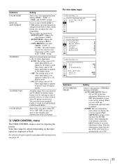
... and 3D display modes. When you set to OFF, this parameter is reset to ON, the automatically adjusted value is applied to 3D display mode. • OFF: The setting value of the LCD panel. For the video input USER CONTROL 1/3 AUTO CHROMA/PHASE AUTO ADJ VALUE: xx S TA RT: USER CONTROL 2/3 SUB CONTROL CONTRAST: x BRIGHTNESS: x CHROMA: x PHASE: x APERTURE: x BACKLIGHT: x USER CONTROL 3/3 PICTURE CONTROL ACC: CTI: V SHARPNESS: INPUT SETTING SHIFT H: SHIFT V: xx x x xxx xx Submenu AUTO CHROMA/ PHASE Setting Adjusts color intensity (CHROMA...
... and 3D display modes. When you set to OFF, this parameter is reset to ON, the automatically adjusted value is applied to 3D display mode. • OFF: The setting value of the LCD panel. For the video input USER CONTROL 1/3 AUTO CHROMA/PHASE AUTO ADJ VALUE: xx S TA RT: USER CONTROL 2/3 SUB CONTROL CONTRAST: x BRIGHTNESS: x CHROMA: x PHASE: x APERTURE: x BACKLIGHT: x USER CONTROL 3/3 PICTURE CONTROL ACC: CTI: V SHARPNESS: INPUT SETTING SHIFT H: SHIFT V: xx x x xxx xx Submenu AUTO CHROMA/ PHASE Setting Adjusts color intensity (CHROMA...
Operating Instructions
Page 34
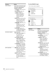
... PICTURE CONTROL INPUT SETTING Setting Adjusts finely the adjustment range of the backlight is changed. Adjusts the picture. • ACC (Auto Color Control): Sets ACC circuit on the front panel for CONTRAST, BRIGHTNESS, CHROMA and PHASE. • CONTRAST: Adjusts the picture contrast. • BRIGHTNESS: Adjusts the picture brightness. • CHROMA: Adjusts color intensity. For the DVI/HD15 input * The 1/3 menu cannot be displayed. The higher the setting, the greater the intensity. The higher the setting, the sharper the picture. When the setting is input, a crisp image...
... PICTURE CONTROL INPUT SETTING Setting Adjusts finely the adjustment range of the backlight is changed. Adjusts the picture. • ACC (Auto Color Control): Sets ACC circuit on the front panel for CONTRAST, BRIGHTNESS, CHROMA and PHASE. • CONTRAST: Adjusts the picture contrast. • BRIGHTNESS: Adjusts the picture brightness. • CHROMA: Adjusts color intensity. For the DVI/HD15 input * The 1/3 menu cannot be displayed. The higher the setting, the greater the intensity. The higher the setting, the sharper the picture. When the setting is input, a crisp image...
Operating Instructions
Page 35
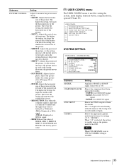
...: LANGUAGE: POWER SAVING: I N G : FUNCTION BUTTON SETTING: COMPUTER DETECT: OPTION DVI SETTING: 3D SETTING: SYSTEM SETTING USER CONFIG - The higher the setting, the larger the vertical size of the picture. Adjust the picture further for a finer picture after APA (page 38) is used mainly in Japan. Select 601 or 709. The 0 setup level is adjusted. • PITCH: Adjusts the horizontal size of the picture with the left . • SHIFT V: Adjusts the position of the CRT. USER CONFIG menu The USER CONFIG menu...
...: LANGUAGE: POWER SAVING: I N G : FUNCTION BUTTON SETTING: COMPUTER DETECT: OPTION DVI SETTING: 3D SETTING: SYSTEM SETTING USER CONFIG - The higher the setting, the larger the vertical size of the picture. Adjust the picture further for a finer picture after APA (page 38) is used mainly in Japan. Select 601 or 709. The 0 setup level is adjusted. • PITCH: Adjusts the horizontal size of the picture with the left . • SHIFT V: Adjusts the position of the CRT. USER CONFIG menu The USER CONFIG menu...
Operating Instructions
Page 36
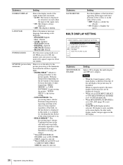
... line in the main display. MULTI DISPLAY SETTING USER CONFIG MULTI DISPLAY SETTING M U LT I D I /P MODE (picture delay minimum) Selects to set to the picture quality. When no signal is input to ON, the monitor goes into power saving mode if no signal is input for about five seconds when the input of the signal starts. • ON: The format is always displayed. • OFF: The display is hidden. In other multi display modes, images appear in the...
... line in the main display. MULTI DISPLAY SETTING USER CONFIG MULTI DISPLAY SETTING M U LT I D I /P MODE (picture delay minimum) Selects to set to the picture quality. When no signal is input to ON, the monitor goes into power saving mode if no signal is input for about five seconds when the input of the signal starts. • ON: The format is always displayed. • OFF: The display is hidden. In other multi display modes, images appear in the...
Operating Instructions
Page 37
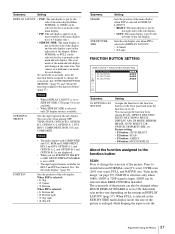
... panel and turns the function on or off. See "FUNCTION BUTTON SETTING" (page 37) and "About the function assigned to switch between NORMAL scan (0% scan), OVER scan (20% over scan), FULL and NATIVE (see "Scan mode image" on the settings in DISPLAY LAYOUT (page 37). The scan mode of the picture can be changed when MULTI DISPLAY ENABLE is set a different scan mode for HD15 and DVI...
... panel and turns the function on or off. See "FUNCTION BUTTON SETTING" (page 37) and "About the function assigned to switch between NORMAL scan (0% scan), OVER scan (20% over scan), FULL and NATIVE (see "Scan mode image" on the settings in DISPLAY LAYOUT (page 37). The scan mode of the picture can be changed when MULTI DISPLAY ENABLE is set a different scan mode for HD15 and DVI...

Operating Instructions
Page 40
..." for each input connector of the monitor 3D SETTING * This setting menu is displayed only when input from the DVI input connectors and OFF not to "PRESET8" when the computer signal is installed. Note "PRESET7" and "PRESET8" will only be displayed when "DVI" is displayed and the CONTROL button cannot be used for left signal input, and the IN (INPUT)-2 connector for the signal from DVI and HD15 input connector. OPTION DVI SETTING * This settings are displayed in the NATIVE scan mode. Select...
..." for each input connector of the monitor 3D SETTING * This setting menu is displayed only when input from the DVI input connectors and OFF not to "PRESET8" when the computer signal is installed. Note "PRESET7" and "PRESET8" will only be displayed when "DVI" is displayed and the CONTROL button cannot be used for left signal input, and the IN (INPUT)-2 connector for the signal from DVI and HD15 input connector. OPTION DVI SETTING * This settings are displayed in the NATIVE scan mode. Select...

Operating Instructions
Page 45
... standard color bar signal) External synchronized input connector BNC type (1) 0.3 Vp-p to 4.0 Vp-p ± bipolarity ternary or negative polarity binary HD15 input connector D-sub 15-pin (1) R/G/B: 0.7 Vp-p, sync positive (Sync On Green, 0.3 Vp-p sync negative) Sync: TTL level (polarity free, H/V separate sync) Plug & Play function: corresponds to DDC2B DVI input connector DVI-D (1) TMDS single link Remote input connector Parallel remote Modular connector 8-pin (1) Serial remote D-sub 9-pin (RS-232C) (1) RJ-45 modular connector (ETHERNET) (1) Optional input port 2 ports Signal format...
... standard color bar signal) External synchronized input connector BNC type (1) 0.3 Vp-p to 4.0 Vp-p ± bipolarity ternary or negative polarity binary HD15 input connector D-sub 15-pin (1) R/G/B: 0.7 Vp-p, sync positive (Sync On Green, 0.3 Vp-p sync negative) Sync: TTL level (polarity free, H/V separate sync) Plug & Play function: corresponds to DDC2B DVI input connector DVI-D (1) TMDS single link Remote input connector Parallel remote Modular connector 8-pin (1) Serial remote D-sub 9-pin (RS-232C) (1) RJ-45 modular connector (ETHERNET) (1) Optional input port 2 ports Signal format...


