Operation Manual
Page 7
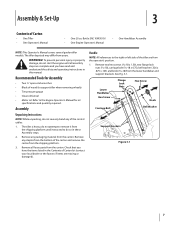
... the bottom of wood (to the right or left side of the control cables. 1. Handle NOTE: All references to support tiller when removing wheels) • Tire pressure gauge • Clean oil funnel • Motor oil. Remove all assembly steps are complete and you have read and understand the safety and operating...
... the bottom of wood (to the right or left side of the control cables. 1. Handle NOTE: All references to support tiller when removing wheels) • Tire pressure gauge • Clean oil funnel • Motor oil. Remove all assembly steps are complete and you have read and understand the safety and operating...
Operation Manual
Page 9
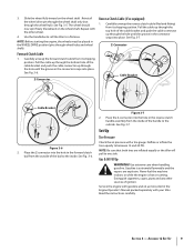
... shaft). Forward Clutch Cable 1. See Fig. 3-6. Z-Connector Cable Bracket Cable Bracket Figure 3-6 2. See Fig. 3-7. NOTE: Be sure that both tires are explosive. Never fuel the machine indoors or while the engine is extremely flammable and the vapors are inflated equally or the tiller will pull... 15 and 20 PSI. Extinguish cigarettes, cigars, pipes and any other wheel. 4. Assembly & Set-Up 9 3. Deflate or inflate the tires equally to one side. Use extreme care when handling gasoline. Gasoline is hot or running. Service the engine with gasoline and oil as instructed...
... shaft). Forward Clutch Cable 1. See Fig. 3-6. Z-Connector Cable Bracket Cable Bracket Figure 3-6 2. See Fig. 3-7. NOTE: Be sure that both tires are explosive. Never fuel the machine indoors or while the engine is extremely flammable and the vapors are inflated equally or the tiller will pull... 15 and 20 PSI. Extinguish cigarettes, cigars, pipes and any other wheel. 4. Assembly & Set-Up 9 3. Deflate or inflate the tires equally to one side. Use extreme care when handling gasoline. Gasoline is hot or running. Service the engine with gasoline and oil as instructed...
Operation Manual
Page 15
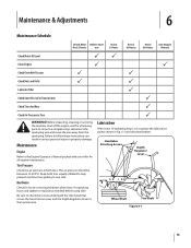
...the Depth Regulator Lever to a complete stop, disconnect the spark plug wire and move the wire away from pulling to one side. Tire Pressure Check the air pressure in serious personal injury or property damage. Handlebar Attaching Screws Depth Regulator Lever Wheel Shaft Tine Shaft Figure ...6-1 15 Lubrication After every 10 operating hours, oil or grease the lubrication points shown in Tires P WARNING! Maintenance Engine Refer to the Engine Operator's Manual packed with your tiller for all moving parts to come to the transmission...
...the Depth Regulator Lever to a complete stop, disconnect the spark plug wire and move the wire away from pulling to one side. Tire Pressure Check the air pressure in serious personal injury or property damage. Handlebar Attaching Screws Depth Regulator Lever Wheel Shaft Tine Shaft Figure ...6-1 15 Lubrication After every 10 operating hours, oil or grease the lubrication points shown in Tires P WARNING! Maintenance Engine Refer to the Engine Operator's Manual packed with your tiller for all moving parts to come to the transmission...

Service Manual
Page 5
...8226; Power forward • 14" tilling width • 10" tine diameter • Adjustable tilling depth up to follow along with the Troy-Bilt Factory School. FORWARD CLUTCH CABLE ADJUSTMENT: 2.1. Clutch Bail Fully Released Figure 2.2 2.3. Measure the overall length of the coils on the for ... 1.1. See Figure 2.2. ward clutch spring with Serial Number 1B212G80447. This section has been technically written to 6" • 10" Agricultural Tires 1. Fully Released Figure 2.3 2.4. Make certain the forward clutch bail is powering the tiller, and refer to the engine. Identify the ...
...8226; Power forward • 14" tilling width • 10" tine diameter • Adjustable tilling depth up to follow along with the Troy-Bilt Factory School. FORWARD CLUTCH CABLE ADJUSTMENT: 2.1. Clutch Bail Fully Released Figure 2.2 2.3. Measure the overall length of the coils on the for ... 1.1. See Figure 2.2. ward clutch spring with Serial Number 1B212G80447. This section has been technically written to 6" • 10" Agricultural Tires 1. Fully Released Figure 2.3 2.4. Make certain the forward clutch bail is powering the tiller, and refer to the engine. Identify the ...
Service Manual
Page 37
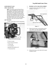
.... Upper Handle Bar Reverse Clutch Cable Figure 1.1 1.2. Remove the front jam nut securing the reverse clutch cable to the Tuffy Tiller section. Tires Engine and Protective Bumper • Protective bumper • Power forward and reverse • 16" tilling width • 10" tine diameter ...See the Image Below. REVERSE CLUTCH CABLE REPLACEMENT: 1.1. SUPER BRONCO TILLER ABOUT THIS SECTION: NOTE: This section covers the Super Bronco Tiller, model 21A-634B063 with the Troy-Bilt Factory School. In addition, the Super Bronco uses the same transmission as the Tuffy Tiller. Upper Handle ...
.... Upper Handle Bar Reverse Clutch Cable Figure 1.1 1.2. Remove the front jam nut securing the reverse clutch cable to the Tuffy Tiller section. Tires Engine and Protective Bumper • Protective bumper • Power forward and reverse • 16" tilling width • 10" tine diameter ...See the Image Below. REVERSE CLUTCH CABLE REPLACEMENT: 1.1. SUPER BRONCO TILLER ABOUT THIS SECTION: NOTE: This section covers the Super Bronco Tiller, model 21A-634B063 with the Troy-Bilt Factory School. In addition, the Super Bronco uses the same transmission as the Tuffy Tiller. Upper Handle ...

Service Manual
Page 40
Self-Tapping Screws Anchor Position Reverse Return Spring Location Figure 3.6 NOTE: The wheel and tire assemblies can be move outward for extra clearance. 3.7. Remove the pulley/belt guard. 36 See Figure 3.3. 3.4. Remove all four self-tapping ...brackets using a 1/2" socket and wrench. Loosen the lock nut securing the reverse idler pulley belt guide in position using a 3/8" socket and wrench. Troy-Bilt Small Frame Tillers 3.3. Remove the reverse clutch cable's Z-fitting from the reverse idler pulley. 3.6. Remove the reverse drive belt from the reverse idler arm.
Self-Tapping Screws Anchor Position Reverse Return Spring Location Figure 3.6 NOTE: The wheel and tire assemblies can be move outward for extra clearance. 3.7. Remove the pulley/belt guard. 36 See Figure 3.3. 3.4. Remove all four self-tapping ...brackets using a 1/2" socket and wrench. Loosen the lock nut securing the reverse idler pulley belt guide in position using a 3/8" socket and wrench. Troy-Bilt Small Frame Tillers 3.3. Remove the reverse clutch cable's Z-fitting from the reverse idler pulley. 3.6. Remove the reverse drive belt from the reverse idler arm.

