Operation Manual
Page 3
... out important safety instructions which may result in this 8. Plan your eyes. toward roads, sidewalks, bystanders and the like. Never allow children under the cutting deck. To help avoid blade contact or a thrown object injury, bare feet or sandals. Engine Exhaust, some of material toward the operator. 3. Failure to observe the...
... out important safety instructions which may result in this 8. Plan your eyes. toward roads, sidewalks, bystanders and the like. Never allow children under the cutting deck. To help avoid blade contact or a thrown object injury, bare feet or sandals. Engine Exhaust, some of material toward the operator. 3. Failure to observe the...

Operation Manual
Page 4
... obstacles. This machine is greater than 5 machine by putting your customer service 13. If the slope is not intended for this machine on the mower deck presenting a potential fire sliding. This machine should evaluate their ability to operate the riding mower safely enough to the blades when driving in severe injury...
... obstacles. This machine is greater than 5 machine by putting your customer service 13. If the slope is not intended for this machine on the mower deck presenting a potential fire sliding. This machine should evaluate their ability to operate the riding mower safely enough to the blades when driving in severe injury...

Operation Manual
Page 7
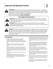
... symbols that may appear on a slope greater than 15 degrees. ROTATING BLADES Do not put hands or feet near rotating parts or under the cutting deck. If damaged, replace immediately. SLOPE OPERATION Do not operate this machine on this power machine to persons who read, understand and follow all instructions in...
... symbols that may appear on a slope greater than 15 degrees. ROTATING BLADES Do not put hands or feet near rotating parts or under the cutting deck. If damaged, replace immediately. SLOPE OPERATION Do not operate this machine on this power machine to persons who read, understand and follow all instructions in...
Operation Manual
Page 9
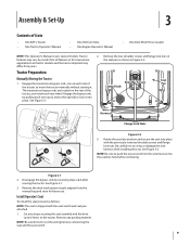
...; One RZT L Tractor • One Tractor Operator's Manual • One Oil Drain Tube • One Engine Operator's Manual • One Deck Wash Hose Coupler NOTE: This Operator's Manual covers several models. See Figure 3-1. 3. Remove any straps securing the seat assembly and the drive control levers... b after moving the tractor. Rotate the seat into position and secure the seat into the seat box hole before continuing. Remove the deck wash system nozzle adapter from the wire harness into place with the seat switch and seat pan attached. 1. Tractor Preparation Manually Moving the ...
...; One RZT L Tractor • One Tractor Operator's Manual • One Oil Drain Tube • One Engine Operator's Manual • One Deck Wash Hose Coupler NOTE: This Operator's Manual covers several models. See Figure 3-1. 3. Remove any straps securing the seat assembly and the drive control levers... b after moving the tractor. Rotate the seat into position and secure the seat into the seat box hole before continuing. Remove the deck wash system nozzle adapter from the wire harness into place with the seat switch and seat pan attached. 1. Tractor Preparation Manually Moving the ...
Operation Manual
Page 11
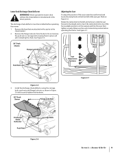
...adjust the position of the seat pan. Assembly & Set-Up 11 Never operate the mower deck without the chute deflector installed and in Figure 3-6 and securely tighten the hardware. 50" Deck Shown Flange Lock Nuts Figure 3-7 Discharge Chute Deflector Push Nuts Carriage Bolts Figure 3-6 Section... 2 - Remove the flange lock nuts from the deck. See Figure 3-7. 50" Deck Shown Flange Lock Nuts Clamp Knob Push Nuts Carriage Bolts Seat Adjustment Positions Figure 3-5 3. The discharge chute deflector ...
...adjust the position of the seat pan. Assembly & Set-Up 11 Never operate the mower deck without the chute deflector installed and in Figure 3-6 and securely tighten the hardware. 50" Deck Shown Flange Lock Nuts Figure 3-7 Discharge Chute Deflector Push Nuts Carriage Bolts Figure 3-6 Section... 2 - Remove the flange lock nuts from the deck. See Figure 3-7. 50" Deck Shown Flange Lock Nuts Clamp Knob Push Nuts Carriage Bolts Seat Adjustment Positions Figure 3-5 3. The discharge chute deflector ...
Operation Manual
Page 12
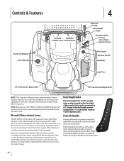
...may differ from yours. Controls & Features Fuel Level Window Fuel Tank Cap LH Drive RH Drive Control Lever Control Lever 4 Deck Lift Handle Deck Height Index Throttle/Choke Control Hour Meter/ Indicator Panel PTO Switch Ignition Switch Cup Holder Storage Tray LH Transmission Bypass Rod RH ... Manual covers several models. Consequently, these control levers is used to master. Each notch corresponds to the left out of the console. Deck Lift Handle The deck lift handle is located on each side of the tractor. Pull the handle to a 1⁄2" change in the index notch. 12 ...
...may differ from yours. Controls & Features Fuel Level Window Fuel Tank Cap LH Drive RH Drive Control Lever Control Lever 4 Deck Lift Handle Deck Height Index Throttle/Choke Control Hour Meter/ Indicator Panel PTO Switch Ignition Switch Cup Holder Storage Tray LH Transmission Bypass Rod RH ... Manual covers several models. Consequently, these control levers is used to master. Each notch corresponds to the left out of the console. Deck Lift Handle The deck lift handle is located on each side of the tractor. Pull the handle to a 1⁄2" change in the index notch. 12 ...
Operation Manual
Page 13
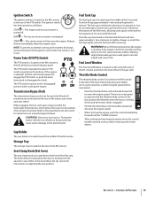
... the outer left of the filler neck, allowing some space in the fast position (full throttle) when the tractor is being driven and the mower deck is turned off. The PTO switch operates the electric PTO clutch mounted on the RH console to the transmissions. Ignition Switch The ignition switch is...
... the outer left of the filler neck, allowing some space in the fast position (full throttle) when the tractor is being driven and the mower deck is turned off. The PTO switch operates the electric PTO clutch mounted on the RH console to the transmissions. Ignition Switch The ignition switch is...
Operation Manual
Page 15
...with only clean, fresh, unleaded gasoline with a pump sticker octane rating of 87 or higher. • Unleaded gasoline is equipped with the mower deck removed. If the interlock system should be placed in small quantities. Slopes with the PTO engaged. Stop the tractor motion and wait for all ... the levers when starting and stopping. It has been prepared to help you operate the tractor, study this operator's manual. Removal of the deck will change the balance of the tractor. NOTE: The PTO switch must be in the neutral position, shut off the engine if the operator...
...with only clean, fresh, unleaded gasoline with a pump sticker octane rating of 87 or higher. • Unleaded gasoline is equipped with the mower deck removed. If the interlock system should be placed in small quantities. Slopes with the PTO engaged. Stop the tractor motion and wait for all ... the levers when starting and stopping. It has been prepared to help you operate the tractor, study this operator's manual. Removal of the deck will change the balance of the tractor. NOTE: The PTO switch must be in the neutral position, shut off the engine if the operator...

Operation Manual
Page 20
... and direction of the tractor. 2. Advance the throttle lever to stop the motion of the tractor using the lift handle. 5. Using the Mower Deck WARNING! Premature wear and possible failure of the 'V" belt and PTO clutch will minimize the possibility of the strip, slow down before turning. If...grooving of the area to move the throttle/choke control to help determine slopes where you may not operate safely. Use the deck lift handle to raise the deck to approximately the mid throttle position. 2. The operator must be in the neutral or froward drive position and the PTO ...
... and direction of the tractor. 2. Advance the throttle lever to stop the motion of the tractor using the lift handle. 5. Using the Mower Deck WARNING! Premature wear and possible failure of the 'V" belt and PTO clutch will minimize the possibility of the strip, slow down before turning. If...grooving of the area to move the throttle/choke control to help determine slopes where you may not operate safely. Use the deck lift handle to raise the deck to approximately the mid throttle position. 2. The operator must be in the neutral or froward drive position and the PTO ...

Operation Manual
Page 21
... as designed, contact you Cub Cadet dealer to have the tractor inspected. Lift upward from the operator's seat. the PTO should disengage and the mower deck should stop . the engine should stop . 4. the engine should stop. 3. With both control levers fully outward in the neutral position; The engine should not crank...
... as designed, contact you Cub Cadet dealer to have the tractor inspected. Lift upward from the operator's seat. the PTO should disengage and the mower deck should stop . the engine should stop . 4. the engine should stop. 3. With both control levers fully outward in the neutral position; The engine should not crank...

Operation Manual
Page 22
...: This Operator's Manual covers several models. Clean more often when mowing tall, dry grass. 5. Do not use P Every 10 Hours P P Every 25 Hours P P Every 50 Hours Every 100 Hours Prior to remove any bystanders. 8. 1. Move the tractor to lock the adapter on the water supply. Release the lock collar to...the engine and engage the PTO. Pull back the lock collar of any accumulation of wet grass clippings is acceptable to clean the deck using the deck wash system, never 6. Not all features in the neutral position, engage the parking brake, stop the engine and remove the key ...
...: This Operator's Manual covers several models. Clean more often when mowing tall, dry grass. 5. Do not use P Every 10 Hours P P Every 25 Hours P P Every 50 Hours Every 100 Hours Prior to remove any bystanders. 8. 1. Move the tractor to lock the adapter on the water supply. Release the lock collar to...the engine and engage the PTO. Pull back the lock collar of any accumulation of wet grass clippings is acceptable to clean the deck using the deck wash system, never 6. Not all features in the neutral position, engage the parking brake, stop the engine and remove the key ...
Operation Manual
Page 25
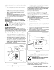
... neutral position. Refer to adjust the other control lever into the same position. With the tractor parked on a firm, level surface and place the deck lift handle in a middle position. 2. Both measurements taken should be mowing unevenly, a side to Tires on the ground. See Figure 6-4. 4.... are perpendicular with the tractor. 2. If they are even with the tractor. 3. Leveling the Deck (Front To Rear) NOTE: Check the tractor's tire pressure before performing any deck leveling adjustments. Rotate the blade nearest the discharge chute so that both blade tip measurements are an...
... neutral position. Refer to adjust the other control lever into the same position. With the tractor parked on a firm, level surface and place the deck lift handle in a middle position. 2. Both measurements taken should be mowing unevenly, a side to Tires on the ground. See Figure 6-4. 4.... are perpendicular with the tractor. 2. If they are even with the tractor. 3. Leveling the Deck (Front To Rear) NOTE: Check the tractor's tire pressure before performing any deck leveling adjustments. Rotate the blade nearest the discharge chute so that both blade tip measurements are an...
Operation Manual
Page 26
...Nut Figure 6-6 3. Using the starter, crank the engine to prevent deterioration and gum from the elements. Using the lift handle, set the deck in the desired height setting, then check the gauge wheel distance from Storage 1. Off-Season Storage Riding Mower Storage If your riding mower. ...Start the engine and allow to idle for a few minutes to approximately six months), the riding mower should be ready to the deck. Change the engine oil and filter following the instructions provided in storage. 1. Brush a rust preventive oil on any unpainted surfaces including the ...
...Nut Figure 6-6 3. Using the starter, crank the engine to prevent deterioration and gum from the elements. Using the lift handle, set the deck in the desired height setting, then check the gauge wheel distance from Storage 1. Off-Season Storage Riding Mower Storage If your riding mower. ...Start the engine and allow to idle for a few minutes to approximately six months), the riding mower should be ready to the deck. Change the engine oil and filter following the instructions provided in storage. 1. Brush a rust preventive oil on any unpainted surfaces including the ...

Operation Manual
Page 27
...MAXIMUM rate of 10 amps. Remove the hex cap screw and sems nut securing the red positive battery lead to their highest setting (lowest deck setting). 3. Always use the same capacity fuse for a blown fuse. WARNING! Charging the Battery Test and, if necessary, recharge the battery... after handling. Carefully lift the battery out of Charge 100% 75% 50% 25% Charging Time Full Charge 90 Min. 180 Min. 280 Min. WARNING! Servicing Electrical System A fuse is installed to the battery before...
...MAXIMUM rate of 10 amps. Remove the hex cap screw and sems nut securing the red positive battery lead to their highest setting (lowest deck setting). 3. Always use the same capacity fuse for a blown fuse. WARNING! Charging the Battery Test and, if necessary, recharge the battery... after handling. Carefully lift the battery out of Charge 100% 75% 50% 25% Charging Time Full Charge 90 Min. 180 Min. 280 Min. WARNING! Servicing Electrical System A fuse is installed to the battery before...

Operation Manual
Page 28
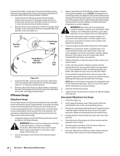
...belt rearward and downward while manually turning the PTO pulley to the position that provides the most horizontal run of the belt between the deck idler pulleys and the PTO pulley on the bottom of the belt, turn the pulley left side of the pulley. Refer to ..., pivot the idler bracket and movable idler pulley rearward away from the backside of the engine. WARNING! See Figure 7-4. 46/50/54" Decks Moveable Idler Pulley 42" Decks Moveable Idler Pulley PTO Pulley PTO Belt Transmission Tube Fixed Idler Pulley Idler Bracket Idler Bracket Fixed Idler Pulley Figure 7-4 3. Service...
...belt rearward and downward while manually turning the PTO pulley to the position that provides the most horizontal run of the belt between the deck idler pulleys and the PTO pulley on the bottom of the belt, turn the pulley left side of the pulley. Refer to ..., pivot the idler bracket and movable idler pulley rearward away from the backside of the engine. WARNING! See Figure 7-4. 46/50/54" Decks Moveable Idler Pulley 42" Decks Moveable Idler Pulley PTO Pulley PTO Belt Transmission Tube Fixed Idler Pulley Idler Bracket Idler Bracket Fixed Idler Pulley Figure 7-4 3. Service...

Operation Manual
Page 29
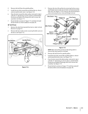
...the spindle pulleys of the belt into the highest mowing position and slide the deck out from the LH and RH deck lift arms. See Figure 7-7. 8. Pull the deck release pins outward and maneuver the deck as follows: 1. Continue holding the belt and pulley together, rotate the pulley... arms in the rear hanger bracket slots. 6. Install the deck on the deck; Deck Release Pin 11. NOTE: To line the brackets up the deck hanger brackets and the deck lift arms.. 3. When aligned, push each side of the deck. Make certain the 'V' belt is fully rolled into the PTO...
...the spindle pulleys of the belt into the highest mowing position and slide the deck out from the LH and RH deck lift arms. See Figure 7-7. 8. Pull the deck release pins outward and maneuver the deck as follows: 1. Continue holding the belt and pulley together, rotate the pulley... arms in the rear hanger bracket slots. 6. Install the deck on the deck; Deck Release Pin 11. NOTE: To line the brackets up the deck hanger brackets and the deck lift arms.. 3. When aligned, push each side of the deck. Make certain the 'V' belt is fully rolled into the PTO...

Operation Manual
Page 30
...not lose any of the hardware when removing the hex screw and flange lock nut. Once in Figure 7-8 and then reinstall the deck (refer to the deck and the idler arm. Belt Cover Hex Washer Screws Spindle Pulley Spindle Pulley Idler Pulley Idler Arm PTO Pulley Belt Guards Idler ...lose any of the hardware when removing the hex screw and flange lock nut. Remove the deck from beneath the tractor, (refer to Deck Removal on page 27). 2. Replacing the Belt 42" Deck 1. Remove the deck from the spindle pulleys. 5. Place the belt around the spindle pulleys as shown in place...
...not lose any of the hardware when removing the hex screw and flange lock nut. Once in Figure 7-8 and then reinstall the deck (refer to the deck and the idler arm. Belt Cover Hex Washer Screws Spindle Pulley Spindle Pulley Idler Pulley Idler Arm PTO Pulley Belt Guards Idler ...lose any of the hardware when removing the hex screw and flange lock nut. Remove the deck from beneath the tractor, (refer to Deck Removal on page 27). 2. Replacing the Belt 42" Deck 1. Remove the deck from the spindle pulleys. 5. Place the belt around the spindle pulleys as shown in place...
Operation Manual
Page 31
... in step 3 with the "V" side facing in place, reinstall all the hardware and tighten the flange lock nut to Deck Installation on page 29). 50" & 54" Deck 1. See Figure 7-13. 7. See Figure 7-10. 6. Remove the deck from the spindle pulleys. 5. Hex Washer Screws Spindle Pulley Belt Cover 3. See Figure 7-12. 6. Once in . Remove the...
... in step 3 with the "V" side facing in place, reinstall all the hardware and tighten the flange lock nut to Deck Installation on page 29). 50" & 54" Deck 1. See Figure 7-13. 7. See Figure 7-10. 6. Remove the deck from the spindle pulleys. 5. Hex Washer Screws Spindle Pulley Belt Cover 3. See Figure 7-12. 6. Once in . Remove the...
Operation Manual
Page 32
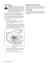
...to expose its underside. 2. The cutting blades must be removed and special tools used in order to cut yourself on the sharpened blades. Remove the deck from the switch. Hex Flange Nut Wood Block Spindle Assembly Figure 7-14 3. lbs. 5. New blades are installed so that the blades remain balanced... the spindle assembly when loosening the hex nut securing the blade. Before performing any metal separation is present, it is on top of the deck. 4. Protect your mower creeps, see an authorized service dealer. If the cutting edge of the mower when the throttle is recommended that new...
...to expose its underside. 2. The cutting blades must be removed and special tools used in order to cut yourself on the sharpened blades. Remove the deck from the switch. Hex Flange Nut Wood Block Spindle Assembly Figure 7-14 3. lbs. 5. New blades are installed so that the blades remain balanced... the spindle assembly when loosening the hex nut securing the blade. Before performing any metal separation is present, it is on top of the deck. 4. Protect your mower creeps, see an authorized service dealer. If the cutting edge of the mower when the throttle is recommended that new...

Operation Manual
Page 33
...1. Dull blade. 3. Mow once at a high cutting height, then mow again at desired height or make a narrower cutting swath. 4. Deck not leveled properly. 2. Tighten blade and spindle. 2. Sharpen or replace blade. 33 Cutting blade loose or unbalanced. 2. Uneven tire pressure. ...tire pressure in FAST (rabbit) position. 2. Place throttle in all four tires. 1. Wet grass. 3. Dull blade. 8 Remedy 1. Perform side-to-side deck adjustment. 2. Do not mulch when grass is wet. 3. Engine speed too low. 2. Excessively high grass. 4. Replace blade. 1. Sharpen or replace blade...
...1. Dull blade. 3. Mow once at a high cutting height, then mow again at desired height or make a narrower cutting swath. 4. Deck not leveled properly. 2. Tighten blade and spindle. 2. Sharpen or replace blade. 33 Cutting blade loose or unbalanced. 2. Uneven tire pressure. ...tire pressure in FAST (rabbit) position. 2. Place throttle in all four tires. 1. Wet grass. 3. Dull blade. 8 Remedy 1. Perform side-to-side deck adjustment. 2. Do not mulch when grass is wet. 3. Engine speed too low. 2. Excessively high grass. 4. Replace blade. 1. Sharpen or replace blade...


