
Operation Manual
Page 1
BOX 361131 CLEVELAND, OHIO 44136-0019 Form No. 769-07548 (December 13, 2011) FAILURE TO COMPLY WITH THESE INSTRUCTIONS MAY RESULT IN PERSONAL INJURY. Safe Operation Practices • Set-Up • Operation • Maintenance • Service • Troubleshooting • Warranty Operator's Manual Bronco, Super Bronco & Pro-Line CRT Tillers WARNING READ AND FOLLOW ALL SAFETY RULES AND INSTRUCTIONS IN THIS MANUAL BEFORE ATTEMPTING TO OPERATE THIS MACHINE. Printed In USA TROY-BILT LLC, P.O.
BOX 361131 CLEVELAND, OHIO 44136-0019 Form No. 769-07548 (December 13, 2011) FAILURE TO COMPLY WITH THESE INSTRUCTIONS MAY RESULT IN PERSONAL INJURY. Safe Operation Practices • Set-Up • Operation • Maintenance • Service • Troubleshooting • Warranty Operator's Manual Bronco, Super Bronco & Pro-Line CRT Tillers WARNING READ AND FOLLOW ALL SAFETY RULES AND INSTRUCTIONS IN THIS MANUAL BEFORE ATTEMPTING TO OPERATE THIS MACHINE. Printed In USA TROY-BILT LLC, P.O.

Operation Manual
Page 2
... refer to Troy-Bilt LLC • P.O. Table of Contents Safe Operation Practices 3 Assembly & Set-Up 7 Control & Features 10 Operation 11 Maintenance & Adjustment 15 Service 17 Troubleshooting 19 Replacement Parts 20 Warranty Back Cover Record Product Information Before setting up , operate and maintain your complete satisfaction at www.opei.org or the engine manufacturer's web site. Please read this manual frequently to familiarize yourself with your new equipment, please locate the model plate...
... refer to Troy-Bilt LLC • P.O. Table of Contents Safe Operation Practices 3 Assembly & Set-Up 7 Control & Features 10 Operation 11 Maintenance & Adjustment 15 Service 17 Troubleshooting 19 Replacement Parts 20 Warranty Back Cover Record Product Information Before setting up , operate and maintain your complete satisfaction at www.opei.org or the engine manufacturer's web site. Please read this manual frequently to familiarize yourself with your new equipment, please locate the model plate...

Operation Manual
Page 3
... should read and understand the instructions and safe operation practices in the manual(s) before attempting to operate this machine without proper instruction. 5. As with the engine running , except where specifically recommended in personal injury. Know how to the safe operation practices in this machine in serious injury. Safe Handling of age to operate this manual in moving parts. This machine is extremely flammable...
... should read and understand the instructions and safe operation practices in the manual(s) before attempting to operate this machine without proper instruction. 5. As with the engine running , except where specifically recommended in personal injury. Know how to the safe operation practices in this machine in serious injury. Safe Handling of age to operate this manual in moving parts. This machine is extremely flammable...
Operation Manual
Page 4
... servicing dealer.. Use only attachments and accessories approved by attempting to prevent unintended starting and operating. 18. When practical, remove gas-powered equipment from the machine while it is complete. If gasoline is an open device. Do not operate machine while under the influence of a rate. 17. Do not change the engine governor settings or over fill fuel tank. Never over -speed the engine. Check their proper operation...
... servicing dealer.. Use only attachments and accessories approved by attempting to prevent unintended starting and operating. 18. When practical, remove gas-powered equipment from the machine while it is complete. If gasoline is an open device. Do not operate machine while under the influence of a rate. 17. Do not change the engine governor settings or over fill fuel tank. Never over -speed the engine. Check their proper operation...

Operation Manual
Page 7
... support tiller when removing wheels) • Tire pressure gauge • Clean oil funnel • Motor oil. Handle NOTE: All references to remove it from the shipping platform until all loose parts from the carton. Recommended Tools for oil specifications and quantity required. Remove any packaging material from the carton. Remove all assembly steps are from the shipping platform. 3. Lower Handlebar Hex Screw Flange Lock Nuts Hex Screw Knob Carriage Bolt Bell Washer Support Brackets Figure 3-1 7 The tiller...
... support tiller when removing wheels) • Tire pressure gauge • Clean oil funnel • Motor oil. Handle NOTE: All references to remove it from the shipping platform until all loose parts from the carton. Recommended Tools for oil specifications and quantity required. Remove any packaging material from the carton. Remove all assembly steps are from the shipping platform. 3. Lower Handlebar Hex Screw Flange Lock Nuts Hex Screw Knob Carriage Bolt Bell Washer Support Brackets Figure 3-1 7 The tiller...
Operation Manual
Page 8
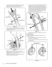
... handlebar support bracket. Use a setting that will not move, loosen the attaching hex screws (5⁄16-18 x .75) and flange lock nuts (5⁄1618) at approximately waist level when the tines are three height adjustment holes in freewheel, as follows: 1. Knob Carriage Bolt Bell Washer Figure 3-4 4. Move Tiller Off Crate To roll the tiller off the ground. 2. Wheel Drive Pin Figure 3-3 NOTE: If a support bracket will position the...
... handlebar support bracket. Use a setting that will not move, loosen the attaching hex screws (5⁄16-18 x .75) and flange lock nuts (5⁄1618) at approximately waist level when the tines are three height adjustment holes in freewheel, as follows: 1. Knob Carriage Bolt Bell Washer Figure 3-4 4. Move Tiller Off Crate To roll the tiller off the ground. 2. Wheel Drive Pin Figure 3-3 NOTE: If a support bracket will position the...

Operation Manual
Page 9
... 3-7 2. Set-Up Tire Pressure Check the air pressure with the other sources of the bail to one side. Use extreme care when handling gasoline. Gasoline is hot or running. Never fuel the machine indoors or while the engine is extremely flammable and the vapors are inflated equally or the tiller will pull to the inside. Service the engine with gasoline and oil as instructed in the WHEEL DRIVE position (pins...
... 3-7 2. Set-Up Tire Pressure Check the air pressure with the other sources of the bail to one side. Use extreme care when handling gasoline. Gasoline is hot or running. Never fuel the machine indoors or while the engine is extremely flammable and the vapors are inflated equally or the tiller will pull to the inside. Service the engine with gasoline and oil as instructed in the WHEEL DRIVE position (pins...
Operation Manual
Page 10
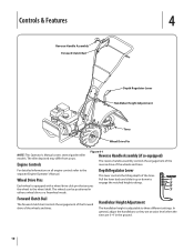
... a wheel drive click pin that secures the wheel to engage the notched height settings. Wheel Drive Pins Each wheel is adjustable to the separate Engine Operator's Manual. Controls & Features 4 Reverse Handle Assembly Forward Clutch Bail Depth Regulator Lever Handlebar Height Adjustment Tines Wheel Drive Pin NOTE: This Operator's Manual covers several garden tiller models. The wheels can be positioned in the ground. 10 The tiller depicted may differ from yours. Pull the lever back and slide it up or down to the wheel shaft...
... a wheel drive click pin that secures the wheel to engage the notched height settings. Wheel Drive Pins Each wheel is adjustable to the separate Engine Operator's Manual. Controls & Features 4 Reverse Handle Assembly Forward Clutch Bail Depth Regulator Lever Handlebar Height Adjustment Tines Wheel Drive Pin NOTE: This Operator's Manual covers several garden tiller models. The wheels can be positioned in the ground. 10 The tiller depicted may differ from yours. Pull the lever back and slide it up or down to the wheel shaft...
Operation Manual
Page 11
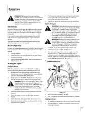
... new operation (see Maintenance & Adjustments Section in this Operation Section and the Engine Operator's Manual before using the tiller controls without the tines engaging the soil (put both wheels in the freewheel position when the engine is running . Check the air cleaner and engine cooling system. Break-In Operation Perform the following checks and services before starting the engine. Tighten or replace as needed. 3. Put the wheels in the WHEEL DRIVE position (wheel pins must be in the wheel drive position before each use: 1. Check the tiller...
... new operation (see Maintenance & Adjustments Section in this Operation Section and the Engine Operator's Manual before using the tiller controls without the tines engaging the soil (put both wheels in the freewheel position when the engine is running . Check the air cleaner and engine cooling system. Break-In Operation Perform the following checks and services before starting the engine. Tighten or replace as needed. 3. Put the wheels in the WHEEL DRIVE position (wheel pins must be in the wheel drive position before each use: 1. Check the tiller...
Operation Manual
Page 15
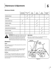
... See Engine Manual Check Motor Oil Level PP Clean Engine P P Check Drive Belt Tension P P Check Nuts and Bolts P P Lubricate Tiller P Check Gear Oil Level in Transmission P Check Tines for Wear P Check Air Pressure in Fig. 6-1 and described below. Maintenance Engine Refer to the Engine Operator's Manual packed with your tiller for all engine maintenance. Before inspecting, cleaning or servicing the machine, shut off the engine, wait for all moving parts to come to a complete stop, disconnect the spark plug wire and move the wire away from pulling to help...
... See Engine Manual Check Motor Oil Level PP Clean Engine P P Check Drive Belt Tension P P Check Nuts and Bolts P P Lubricate Tiller P Check Gear Oil Level in Transmission P Check Tines for Wear P Check Air Pressure in Fig. 6-1 and described below. Maintenance Engine Refer to the Engine Operator's Manual packed with your tiller for all engine maintenance. Before inspecting, cleaning or servicing the machine, shut off the engine, wait for all moving parts to come to a complete stop, disconnect the spark plug wire and move the wire away from pulling to help...
Operation Manual
Page 16
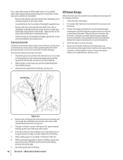
... Fig. 6-2. 5. Use a file or sandpaper to locate the main drive shaft situated below the hole. Operating the tiller when the transmission is low on level ground, pull the Depth Regulator Lever all the way up the side of the main drive shaft. 6. With the tiller on oil can result in the shaft). Clean the tiller and engine. 2. Remove the oil fill plug from gum deposits by removing fuel or by following the storage instructions found...
... Fig. 6-2. 5. Use a file or sandpaper to locate the main drive shaft situated below the hole. Operating the tiller when the transmission is low on level ground, pull the Depth Regulator Lever all the way up the side of the main drive shaft. 6. With the tiller on oil can result in the shaft). Clean the tiller and engine. 2. Remove the oil fill plug from gum deposits by removing fuel or by following the storage instructions found...
Operation Manual
Page 17
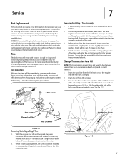
... off and the spark plug wire disconnected, remove the two hex screws (3⁄8-16 x 1.00) and hex lock nuts (3⁄8-16) that the cutting (sharp) edge of each tine assembly so that attach a single tine to reinstall the belt cover. Drain the gasoline from the engine. 3. If needed . Before reinstalling the tine assembly, inspect the tine shaft for ordering information. NOTE: When reinstalling the belt cover, be changed unless it...
... off and the spark plug wire disconnected, remove the two hex screws (3⁄8-16 x 1.00) and hex lock nuts (3⁄8-16) that the cutting (sharp) edge of each tine assembly so that attach a single tine to reinstall the belt cover. Drain the gasoline from the engine. 3. If needed . Before reinstalling the tine assembly, inspect the tine shaft for ordering information. NOTE: When reinstalling the belt cover, be changed unless it...
Operation Manual
Page 19
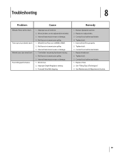
... authorized dealer. 1. Worn tines. 2. Contact local authorized dealer. 4. Contact local authorized dealer. 1. Review Operation section. 2. Replace Tines. 2. Inserts Drive Pins properly. 2. See "Tilling Tips & Techniques." 3. Troubleshooting 8 Problem Cause Wheels/Tines will not turn Tines turn, but wheels don't Wheels turn, but tines Don't Poor tilling performance 1. Bolt loose in transmission pulley. 3. Improper use of controls. 2. Internal transmission wear or damage. 4. Improper Depth Regulator setting. 3. Replace hardware. 2. See Maintenance & Adjustments Section. 19
... authorized dealer. 1. Worn tines. 2. Contact local authorized dealer. 4. Contact local authorized dealer. 1. Review Operation section. 2. Replace Tines. 2. Inserts Drive Pins properly. 2. See "Tilling Tips & Techniques." 3. Troubleshooting 8 Problem Cause Wheels/Tines will not turn Tines turn, but wheels don't Wheels turn, but tines Don't Poor tilling performance 1. Bolt loose in transmission pulley. 3. Improper use of controls. 2. Internal transmission wear or damage. 4. Improper Depth Regulator setting. 3. Replace hardware. 2. See Maintenance & Adjustments Section. 19
Operation Manual
Page 24
... as lubricants, filters, blade sharpening, tune-ups, brake adjustments, clutch adjustments, deck adjustments, and normal deterioration of the product shall void this warranty provide the sole and exclusive remedy arising from state to state. Alteration of safety features of the exterior finish due to use with respect to any warranty for whom it was purchased as : grass collectors and mulch kits. Troy-Bilt LLC, P.O. MANUFACTURER...
... as lubricants, filters, blade sharpening, tune-ups, brake adjustments, clutch adjustments, deck adjustments, and normal deterioration of the product shall void this warranty provide the sole and exclusive remedy arising from state to state. Alteration of safety features of the exterior finish due to use with respect to any warranty for whom it was purchased as : grass collectors and mulch kits. Troy-Bilt LLC, P.O. MANUFACTURER...
Service Manual
Page 3
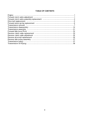
TABLE OF CONTENTS Engine: ...1 Forward clutch cable adjustment 1 Forward clutch cable assembly replacement 3 Drive belt replacement 5 Forward return spring replacement 6 Transmission removal: ...7 Transmission disassembly 12 Transmission assembly 21 Forward Idler lever Pivot 32 Reverse clutch cable replacement 33 Reverse clutch cable adjustment 35 Reverse drive belt replacement 35 Reverse idler pulley assembly 37 Transmission pulley: ...37 Transmission oil fill plug 38 0
TABLE OF CONTENTS Engine: ...1 Forward clutch cable adjustment 1 Forward clutch cable assembly replacement 3 Drive belt replacement 5 Forward return spring replacement 6 Transmission removal: ...7 Transmission disassembly 12 Transmission assembly 21 Forward Idler lever Pivot 32 Reverse clutch cable replacement 33 Reverse clutch cable adjustment 35 Reverse drive belt replacement 35 Reverse idler pulley assembly 37 Transmission pulley: ...37 Transmission oil fill plug 38 0

Service Manual
Page 5
... with Serial Number 1B212G80447. Spark Plug Boot Grounded Figure 2.1 Coil Length - Identify the engine that is fully released. See Figure 2.1. See Figure 2.2. Record the forward clutch spring measurement _____. 1 This section has been technically written to the Engine Owner's Manual for - FORWARD CLUTCH CABLE ADJUSTMENT: 2.1. Measure the overall length of the coils on the for more information. 2. Troy-Bilt Small Frame Tillers Troy-Bilt Small Frame Tillers TUFFY TILLER ABOUT...
... with Serial Number 1B212G80447. Spark Plug Boot Grounded Figure 2.1 Coil Length - Identify the engine that is fully released. See Figure 2.1. See Figure 2.2. Record the forward clutch spring measurement _____. 1 This section has been technically written to the Engine Owner's Manual for - FORWARD CLUTCH CABLE ADJUSTMENT: 2.1. Measure the overall length of the coils on the for more information. 2. Troy-Bilt Small Frame Tillers Troy-Bilt Small Frame Tillers TUFFY TILLER ABOUT...
Service Manual
Page 7
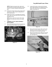
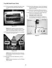
... forward clutch cable assembly to the engine. Spark Plug Troy-Bilt Small Frame Tillers 3.2. Spark Plug Boot Grounded Lower Handle Bracket Figure 3.1 Forward Clutch Cable Figure 3.4 3 Remove the spark plug boot from the spark plug, and ground it counter-clockwise (away from the adjustment screw by rotating it to the adjustment screw using a pair of needle nose pliers. Tighten the hex jam nut up against the forward clutch cable end using a 3/8" wrench and a small adjustable wrench. Perform the forward clutch spring...
... forward clutch cable assembly to the engine. Spark Plug Troy-Bilt Small Frame Tillers 3.2. Spark Plug Boot Grounded Lower Handle Bracket Figure 3.1 Forward Clutch Cable Figure 3.4 3 Remove the spark plug boot from the spark plug, and ground it counter-clockwise (away from the adjustment screw by rotating it to the adjustment screw using a pair of needle nose pliers. Tighten the hex jam nut up against the forward clutch cable end using a 3/8" wrench and a small adjustable wrench. Perform the forward clutch spring...
Service Manual
Page 10
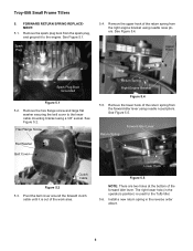
... Lever Clutch Cable Figure 5.2 5.3. Lower Hook Figure 5.5 NOTE: There are two holes at the bottom of the return spring from the spark plug, and ground it is used for the Tuffy tiller. 5.6. FORWARD RETURN SPRING REPLACEMENT: 5.1. Install a new return spring in the operators position) is out of the return spring from the forward idler lever using needle nosed pliers. Troy-Bilt Small Frame Tillers 5. Remove the spark plug boot from the right engine bracket using a 3/8" socket. Remove...
... Lever Clutch Cable Figure 5.2 5.3. Lower Hook Figure 5.5 NOTE: There are two holes at the bottom of the return spring from the spark plug, and ground it is used for the Tuffy tiller. 5.6. FORWARD RETURN SPRING REPLACEMENT: 5.1. Install a new return spring in the operators position) is out of the return spring from the forward idler lever using needle nosed pliers. Troy-Bilt Small Frame Tillers 5. Remove the spark plug boot from the right engine bracket using a 3/8" socket. Remove...

Service Manual
Page 30
... wheel shaft worm gear and spacer, and into the wheel shaft worm gear. 8.39. Magnetic Stand Spacer Spacer Figure 8.37 8.38. PVC pipe by 7" long works well as a bushing installation tool. 8.42. Pull Shaft Out Dial Indicator Figure 8.43 8.44. See Figure 8.41. See Figure 8.35. 8.41. Troy-Bilt Small Frame Tillers 8.35. Drive the second wheel shaft bronze bushing into the transmission housing until it contacts the wheel shaft...
... wheel shaft worm gear and spacer, and into the wheel shaft worm gear. 8.39. Magnetic Stand Spacer Spacer Figure 8.37 8.38. PVC pipe by 7" long works well as a bushing installation tool. 8.42. Pull Shaft Out Dial Indicator Figure 8.43 8.44. See Figure 8.41. See Figure 8.35. 8.41. Troy-Bilt Small Frame Tillers 8.35. Drive the second wheel shaft bronze bushing into the transmission housing until it contacts the wheel shaft...
Service Manual
Page 36
... the transmission covers to operating the tiller. 9. Place new front and rear housing cover gaskets in position. NOTE: The front transmission cover's oil fill plug faces rearward. 32 FORWARD IDLER LEVER PIVOT: 9.1. Perform the Forward Clutch Cable Adjustment section prior to the transmission with gear oil until it is facing in the reverse order to complete the tiller assembly. 8.122. Hex Screw Idler Pulley Figure 8.117 NOTE: When refilling an empty transmission, use only GL-4 gear oil...
... the transmission covers to operating the tiller. 9. Place new front and rear housing cover gaskets in position. NOTE: The front transmission cover's oil fill plug faces rearward. 32 FORWARD IDLER LEVER PIVOT: 9.1. Perform the Forward Clutch Cable Adjustment section prior to the transmission with gear oil until it is facing in the reverse order to complete the tiller assembly. 8.122. Hex Screw Idler Pulley Figure 8.117 NOTE: When refilling an empty transmission, use only GL-4 gear oil...


