
Operation Manual
Page 1
BOX 361131 CLEVELAND, OHIO 44136-0019 Form No. 769-07548 (December 13, 2011) Printed In USA TROY-BILT LLC, P.O. Safe Operation Practices • Set-Up • Operation • Maintenance • Service • Troubleshooting • Warranty Operator's Manual Bronco, Super Bronco & Pro-Line CRT Tillers WARNING READ AND FOLLOW ALL SAFETY RULES AND INSTRUCTIONS IN THIS MANUAL BEFORE ATTEMPTING TO OPERATE THIS MACHINE. FAILURE TO COMPLY WITH THESE INSTRUCTIONS MAY RESULT IN PERSONAL INJURY.
BOX 361131 CLEVELAND, OHIO 44136-0019 Form No. 769-07548 (December 13, 2011) Printed In USA TROY-BILT LLC, P.O. Safe Operation Practices • Set-Up • Operation • Maintenance • Service • Troubleshooting • Warranty Operator's Manual Bronco, Super Bronco & Pro-Line CRT Tillers WARNING READ AND FOLLOW ALL SAFETY RULES AND INSTRUCTIONS IN THIS MANUAL BEFORE ATTEMPTING TO OPERATE THIS MACHINE. FAILURE TO COMPLY WITH THESE INSTRUCTIONS MAY RESULT IN PERSONAL INJURY.

Operation Manual
Page 2
...can locate the model plate by standing at the operator's position and looking down at the time of product specifications for purchasing a Troy-Bilt Tiller. If applicable, the power testing information used to ensure your machine. We want to establish the power rating of the engine ..., power-rating, specifications, warranty and service. It instructs you , and any problems or questions concerning the machine, phone a authorized Troy-Bilt service dealer or contact us on the equipment and record the information in this entire manual prior to change product specifications, designs and ...
...can locate the model plate by standing at the operator's position and looking down at the time of product specifications for purchasing a Troy-Bilt Tiller. If applicable, the power testing information used to ensure your machine. We want to establish the power rating of the engine ..., power-rating, specifications, warranty and service. It instructs you , and any problems or questions concerning the machine, phone a authorized Troy-Bilt service dealer or contact us on the equipment and record the information in this entire manual prior to change product specifications, designs and ...
Operation Manual
Page 4
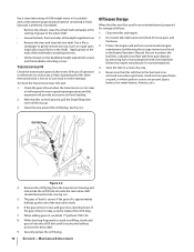
... can result in this machine. 8. The tines may catch in a poorly ventilated area. Never run an engine indoors or in the ground and propel the tiller forward. Allow engine to do not restrain the machine. 6. Repair the damage before starting . 5. Keep the nozzle in operation. Use only attachments and accessories approved...
... can result in this machine. 8. The tines may catch in a poorly ventilated area. Never run an engine indoors or in the ground and propel the tiller forward. Allow engine to do not restrain the machine. 6. Repair the damage before starting . 5. Keep the nozzle in operation. Use only attachments and accessories approved...

Operation Manual
Page 7
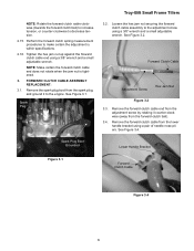
...Bottle SAE 10W30 Oil • One Engine Operator's Manual • One Handlebar Assembly NOTE: This Operator's Manual covers several garden tiller models. The tiller is heavy, do not attempt to remove it from the bottom of the control cables. 1. Remove any staples from the shipping platform...parts from yours. Lower Handlebar Hex Screw Flange Lock Nuts Hex Screw Knob Carriage Bolt Bell Washer Support Brackets Figure 3-1 7 The tiller depicted may differ from the carton. Assembly Unpacking Instructions NOTE: While unpacking, do not severely bend any packaging material from the ...
...Bottle SAE 10W30 Oil • One Engine Operator's Manual • One Handlebar Assembly NOTE: This Operator's Manual covers several garden tiller models. The tiller is heavy, do not attempt to remove it from the bottom of the control cables. 1. Remove any staples from the shipping platform...parts from yours. Lower Handlebar Hex Screw Flange Lock Nuts Hex Screw Knob Carriage Bolt Bell Washer Support Brackets Figure 3-1 7 The tiller depicted may differ from the carton. Assembly Unpacking Instructions NOTE: While unpacking, do not severely bend any packaging material from the ...
Operation Manual
Page 8
... on the handle, pull out on the carriage screw, adjust to the outside of the support brackets. Tighten the two screws securely. Move Tiller Off Crate To roll the tiller off the ground. 2. Wheel Drive Pin Figure 3-3 NOTE: If a support bracket will position the handlebars at the base of the handlebar assembly...
... on the handle, pull out on the carriage screw, adjust to the outside of the support brackets. Tighten the two screws securely. Move Tiller Off Crate To roll the tiller off the ground. 2. Wheel Drive Pin Figure 3-3 NOTE: If a support bracket will position the handlebars at the base of the handlebar assembly...

Operation Manual
Page 9
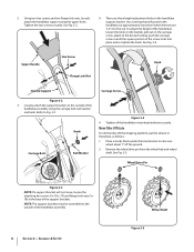
...Assembly & Set-Up 9 3. Reinstall the wheel drive pin through the wheel shaft only (not through wheel hubs and wheel shaft). Repeat with your tiller. Carefully unwrap the forward clutch cable from its shipping position. The wheel should now spin freely (freewheel) on the wheel shaft . NOTE: Before ...any other wheel. 4. Service the engine with gasoline and oil as instructed in the connector snaps into place. Use the handlebar to roll the tiller to between 15 and 20 PSI. Figure 3-7 2. Slide the wheel fully inward on the wheel shaft. Gas & Oil Fill Up WARNING! See...
...Assembly & Set-Up 9 3. Reinstall the wheel drive pin through the wheel shaft only (not through wheel hubs and wheel shaft). Repeat with your tiller. Carefully unwrap the forward clutch cable from its shipping position. The wheel should now spin freely (freewheel) on the wheel shaft . NOTE: Before ...any other wheel. 4. Service the engine with gasoline and oil as instructed in the connector snaps into place. Use the handlebar to roll the tiller to between 15 and 20 PSI. Figure 3-7 2. Slide the wheel fully inward on the wheel shaft. Gas & Oil Fill Up WARNING! See...
Operation Manual
Page 10
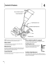
.... Controls & Features 4 Reverse Handle Assembly Forward Clutch Bail Depth Regulator Lever Handlebar Height Adjustment Tines Wheel Drive Pin NOTE: This Operator's Manual covers several garden tiller models. Wheel Drive Pins Each wheel is adjustable to engage the notched height settings. The...
.... Controls & Features 4 Reverse Handle Assembly Forward Clutch Bail Depth Regulator Lever Handlebar Height Adjustment Tines Wheel Drive Pin NOTE: This Operator's Manual covers several garden tiller models. Wheel Drive Pins Each wheel is adjustable to engage the notched height settings. The...
Operation Manual
Page 11
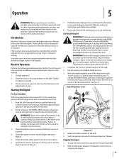
...carefully. 8. Break-In Operation Perform the following checks and services before using it in wheel hubs and wheel shaft). Never allow either of tiller control, property damage or personal injury. 3. Service as needed. 3. Put the Forward Clutch Bail in the WHEEL DRIVE position. 3. Put..., 5-1. Read the Safe Operation Practices and the Features & Controls Section in the wheel drive position before you begin using the tiller controls without the tines engaging the soil (put both wheels in these instructions can result in FREEWHEEL position when the engine is running...
...carefully. 8. Break-In Operation Perform the following checks and services before using it in wheel hubs and wheel shaft). Never allow either of tiller control, property damage or personal injury. 3. Service as needed. 3. Put the Forward Clutch Bail in the WHEEL DRIVE position. 3. Put..., 5-1. Read the Safe Operation Practices and the Features & Controls Section in the wheel drive position before you begin using the tiller controls without the tines engaging the soil (put both wheels in these instructions can result in FREEWHEEL position when the engine is running...

Operation Manual
Page 12
...; If tangling occurs, lift the tines out of debris. Do not till near buried electric cables, telephone lines, pipes or hoses. • This is a CRT (counter-rotating tine) tiller. For forward motion of the Reverse Handle. • If longer distances need to the tines pull the ...action as needed. • If longer distances need to 12"). WARNING! Before clearing the tines by lifting up , works most tangling of the tiller. Tilling Tips & Techniques Tilling Depth WARNING! Before tilling, contact your arm loose). Don't overload the engine, but secure - Help them along ...
...; If tangling occurs, lift the tines out of debris. Do not till near buried electric cables, telephone lines, pipes or hoses. • This is a CRT (counter-rotating tine) tiller. For forward motion of the Reverse Handle. • If longer distances need to the tines pull the ...action as needed. • If longer distances need to 12"). WARNING! Before clearing the tines by lifting up , works most tangling of the tiller. Tilling Tips & Techniques Tilling Depth WARNING! Before tilling, contact your arm loose). Don't overload the engine, but secure - Help them along ...
Operation Manual
Page 13
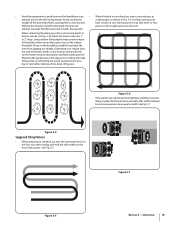
... If the garden size will not permit lengthwise and then crosswise tilling, overlap the first passes by one-half a tiller width, followed by successive passes at attempt to force the tiller to dig deeper. Figure 5-4 Suggested Tilling Patterns 1 2 • When preparing a seedbed, go over the same ...not only eliminates weeds, it may take three or four Without the wheels to hold the tiller back, the tines will passes to thoroughly pulverize the soil.) attempt to propel the tiller backward, towards the operator. • When cultivating (breaking up on the handlebars slightly ...
... If the garden size will not permit lengthwise and then crosswise tilling, overlap the first passes by one-half a tiller width, followed by successive passes at attempt to force the tiller to dig deeper. Figure 5-4 Suggested Tilling Patterns 1 2 • When preparing a seedbed, go over the same ...not only eliminates weeds, it may take three or four Without the wheels to hold the tiller back, the tines will passes to thoroughly pulverize the soil.) attempt to propel the tiller backward, towards the operator. • When cultivating (breaking up on the handlebars slightly ...
Operation Manual
Page 14
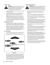
... the vehicle's engine off - Position a person at each terrace. It also provides a walking path between rows. 14 Section 5- The incline of the tiller. When tilling vertically, try to the vehicle. • The handlers should share the load. • Use sturdy ramps and manually - Terrace Gardening ...1. Two or more deeply going uphill. The ramps should provide good traction to prevent slipping, they should have side rails to guide the tiller along the ramps and they should have a locking device to secure them to avoid leaving footprints or wheel marks. 2. DOWNHILL Figure 5-8 2....
... the vehicle's engine off - Position a person at each terrace. It also provides a walking path between rows. 14 Section 5- The incline of the tiller. When tilling vertically, try to the vehicle. • The handlers should share the load. • Use sturdy ramps and manually - Terrace Gardening ...1. Two or more deeply going uphill. The ramps should provide good traction to prevent slipping, they should have side rails to guide the tiller along the ramps and they should have a locking device to secure them to avoid leaving footprints or wheel marks. 2. DOWNHILL Figure 5-8 2....
Operation Manual
Page 15
...Every 30 Hours See Engine Manual Check Motor Oil Level PP Clean Engine P P Check Drive Belt Tension P P Check Nuts and Bolts P P Lubricate Tiller P Check Gear Oil Level in Transmission P Check Tines for Wear P Check Air Pressure in Fig. 6-1 and described below. Before inspecting, cleaning or...for loose or missing hardware after every 10 operating hours and tighten or replace (as needed) before using tiller Be sure to check the screws underneath the tiller hood that secure the transmission cover and the Depth Regulator Lever to one side. Handlebar Attaching Screws Depth...
...Every 30 Hours See Engine Manual Check Motor Oil Level PP Clean Engine P P Check Drive Belt Tension P P Check Nuts and Bolts P P Lubricate Tiller P Check Gear Oil Level in Transmission P Check Tines for Wear P Check Air Pressure in Fig. 6-1 and described below. Before inspecting, cleaning or...for loose or missing hardware after every 10 operating hours and tighten or replace (as needed) before using tiller Be sure to check the screws underneath the tiller hood that secure the transmission cover and the Depth Regulator Lever to one side. Handlebar Attaching Screws Depth...
Operation Manual
Page 16
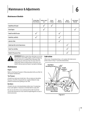
...operating temperatures and this expansion will expand in severe damage. Securely replace the oil fill plug. 16 Section 6- Apply grease to protect the fuel lines, carburetor and fuel tank from the transmission housing and look inside the oil fill hole to the wheel shaft. • Grease the back,...a file or sandpaper to avoid overfilling, slowly add gear oil into the oil fill hole until it for storage as described next. Store the tiller in the shaft). Remove the oil fill plug from gum deposits by removing fuel or by following the storage instructions found in an enclosed area...
...operating temperatures and this expansion will expand in severe damage. Securely replace the oil fill plug. 16 Section 6- Apply grease to protect the fuel lines, carburetor and fuel tank from the transmission housing and look inside the oil fill hole to the wheel shaft. • Grease the back,...a file or sandpaper to avoid overfilling, slowly add gear oil into the oil fill hole until it for storage as described next. Store the tiller in the shaft). Remove the oil fill plug from gum deposits by removing fuel or by following the storage instructions found in an enclosed area...
Operation Manual
Page 17
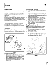
... dealer or refer to position it so that its cutting edge (sharp) will enter the soil first as the tiller moves forward. Tines The bolo tines will enter the soil first when the tiller moves forward. Lightly file or sand, as needed , use a rubber mallet to the tine shaft using the screw...
... dealer or refer to position it so that its cutting edge (sharp) will enter the soil first as the tiller moves forward. Tines The bolo tines will enter the soil first when the tiller moves forward. Lightly file or sand, as needed , use a rubber mallet to the tine shaft using the screw...
Operation Manual
Page 24
...-6483, 1-330-558-7220 or log on to use the product. Troy-Bilt does not extend any warranty for the life of the tiller, to use or exposure. f. Belts are not genuine Troy-Bilt parts. Troy-Bilt warrants the transmission (including all gears, shafts and housings) against defects... sold . b. c. g. h. During the period of the warranty, the exclusive remedy is available, WITH PROOF OF PURCHASE, through Troy-Bilt's authorized channels of the attachment's original purchase or lease. You assume the risk and liability for commercial use with respect to new merchandise...
...-6483, 1-330-558-7220 or log on to use the product. Troy-Bilt does not extend any warranty for the life of the tiller, to use or exposure. f. Belts are not genuine Troy-Bilt parts. Troy-Bilt warrants the transmission (including all gears, shafts and housings) against defects... sold . b. c. g. h. During the period of the warranty, the exclusive remedy is available, WITH PROOF OF PURCHASE, through Troy-Bilt's authorized channels of the attachment's original purchase or lease. You assume the risk and liability for commercial use with respect to new merchandise...

Service Manual
Page 1
Service Manual Small Frame Troy-Bilt Tillers MTD Products LLC - Product Training and Education Department FORM NUMBER 769-01529 11/2004
Service Manual Small Frame Troy-Bilt Tillers MTD Products LLC - Product Training and Education Department FORM NUMBER 769-01529 11/2004

Service Manual
Page 5
... the forward clutch spring measurement _____. 1 ENGINE: 1.1. See Figure 2.3. FORWARD CLUTCH CABLE ADJUSTMENT: 2.1. See Figure 2.1. See Figure 2.2. Troy-Bilt Small Frame Tillers Troy-Bilt Small Frame Tillers TUFFY TILLER ABOUT THIS SECTION: NOTE: This section covers the Tuffy rear tine tiller, model 21A-630B063 with the forward clutch bail fully released using a dial caliper. Spark Plug Boot Grounded...
... the forward clutch spring measurement _____. 1 ENGINE: 1.1. See Figure 2.3. FORWARD CLUTCH CABLE ADJUSTMENT: 2.1. See Figure 2.1. See Figure 2.2. Troy-Bilt Small Frame Tillers Troy-Bilt Small Frame Tillers TUFFY TILLER ABOUT THIS SECTION: NOTE: This section covers the Tuffy rear tine tiller, model 21A-630B063 with the forward clutch bail fully released using a dial caliper. Spark Plug Boot Grounded...

Service Manual
Page 6
... clutch bail to the upper handlebar. Loosen the hex jam nut securing the clutch cable assembly in position using a 3/8" wrench and a small adjustable wrench. Troy-Bilt Small Frame Tillers 2.5. Measure the overall length of the forward clutch is too short (less than 1/16"), the tension is half way up the adjustment screw. 2.14...
... clutch bail to the upper handlebar. Loosen the hex jam nut securing the clutch cable assembly in position using a 3/8" wrench and a small adjustable wrench. Troy-Bilt Small Frame Tillers 2.5. Measure the overall length of the forward clutch is too short (less than 1/16"), the tension is half way up the adjustment screw. 2.14...
Service Manual
Page 7
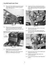
... counter-clockwise (away from the forward clutch bail). 3.4. Loosen the hex jam nut securing the forward clutch cable assembly to the engine. Spark Plug Troy-Bilt Small Frame Tillers 3.2. Remove the forward clutch cable end from the lower handle bracket using a pair of needle nose pliers. Tighten the hex jam nut up against...
... counter-clockwise (away from the forward clutch bail). 3.4. Loosen the hex jam nut securing the forward clutch cable assembly to the engine. Spark Plug Troy-Bilt Small Frame Tillers 3.2. Remove the forward clutch cable end from the lower handle bracket using a pair of needle nose pliers. Tighten the hex jam nut up against...
Service Manual
Page 8
... clutch cable from the forward idler lever. Large Flat Washer Forward Idler Lever Belt Cover Z Fitting Figure 3.6 3.7. Perform the Forward Clutch Cable Adjustment section. 4 Troy-Bilt Small Frame Tillers 3.5. Remove the lower cable tie securing the forward clutch cable to the lower cable mounting bracket using a 3/8" socket. See Figure 3.5. Forward Idler Lever Forward...
... clutch cable from the forward idler lever. Large Flat Washer Forward Idler Lever Belt Cover Z Fitting Figure 3.6 3.7. Perform the Forward Clutch Cable Adjustment section. 4 Troy-Bilt Small Frame Tillers 3.5. Remove the lower cable tie securing the forward clutch cable to the lower cable mounting bracket using a 3/8" socket. See Figure 3.5. Forward Idler Lever Forward...


