
Operation Manual
Page 1
Safe Operation Practices • Set-Up • Operation • Maintenance • Service • Troubleshooting • Warranty Operator's Manual Bronco, Super Bronco & Pro-Line CRT Tillers WARNING READ AND FOLLOW ALL SAFETY RULES AND INSTRUCTIONS IN THIS MANUAL BEFORE ATTEMPTING TO OPERATE THIS MACHINE. BOX 361131 CLEVELAND, OHIO 44136-0019 Form No. 769-07548 (December 13, 2011) Printed In USA TROY-BILT LLC, P.O. FAILURE TO COMPLY WITH THESE INSTRUCTIONS MAY RESULT IN PERSONAL INJURY.
Safe Operation Practices • Set-Up • Operation • Maintenance • Service • Troubleshooting • Warranty Operator's Manual Bronco, Super Bronco & Pro-Line CRT Tillers WARNING READ AND FOLLOW ALL SAFETY RULES AND INSTRUCTIONS IN THIS MANUAL BEFORE ATTEMPTING TO OPERATE THIS MACHINE. BOX 361131 CLEVELAND, OHIO 44136-0019 Form No. 769-07548 (December 13, 2011) Printed In USA TROY-BILT LLC, P.O. FAILURE TO COMPLY WITH THESE INSTRUCTIONS MAY RESULT IN PERSONAL INJURY.

Operation Manual
Page 2
...plate on the equipment and record the information in personal injury or property damage. Failure to do NOT return the machine to Troy-Bilt LLC • P.O. All information in this manual is responsible for more information. Choose from the operating position The engine ...or the engine manufacturer's web site. We reserve the right to establish the power rating of product specifications for purchasing a Troy-Bilt Tiller. If applicable, the power testing information used to change product specifications, designs and equipment without notice and without first contacting the...
...plate on the equipment and record the information in personal injury or property damage. Failure to do NOT return the machine to Troy-Bilt LLC • P.O. All information in this manual is responsible for more information. Choose from the operating position The engine ...or the engine manufacturer's web site. We reserve the right to establish the power rating of product specifications for purchasing a Troy-Bilt Tiller. If applicable, the power testing information used to change product specifications, designs and equipment without notice and without first contacting the...
Operation Manual
Page 24
...in material and workmanship for the life of the tiller, to the original purchaser only, commencing on the date of original purchase or lease. To locate the dealer in the following cases: a. Check your Yellow Pages, or contact Troy-Bilt LLC at www.mtdcanada.com. In Canada Contact...only apply if this product has been operated and maintained in accordance with the Operator's Manual furnished with respect to any product, shall bind Troy-Bilt. Troy-Bilt warrants the transmission (including all gears, shafts and housings) against defects in material and workmanship for a period of one (1) year, ...
...in material and workmanship for the life of the tiller, to the original purchaser only, commencing on the date of original purchase or lease. To locate the dealer in the following cases: a. Check your Yellow Pages, or contact Troy-Bilt LLC at www.mtdcanada.com. In Canada Contact...only apply if this product has been operated and maintained in accordance with the Operator's Manual furnished with respect to any product, shall bind Troy-Bilt. Troy-Bilt warrants the transmission (including all gears, shafts and housings) against defects in material and workmanship for a period of one (1) year, ...

Service Manual
Page 1
Product Training and Education Department FORM NUMBER 769-01529 11/2004 Service Manual Small Frame Troy-Bilt Tillers MTD Products LLC -
Product Training and Education Department FORM NUMBER 769-01529 11/2004 Service Manual Small Frame Troy-Bilt Tillers MTD Products LLC -

Service Manual
Page 5
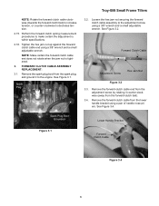
...; 10" tine diameter • Adjustable tilling depth up to follow along with the Troy-Bilt Factory School. Fully Released Figure 2.3 2.4. Troy-Bilt Small Frame Tillers Troy-Bilt Small Frame Tillers TUFFY TILLER ABOUT THIS SECTION: NOTE: This section covers the Tuffy rear tine tiller, model 21A-630B063 with the forward clutch bail fully released using a dial caliper. ENGINE... from the spark plug, and ground it to the Engine Owner's Manual for - Make certain the forward clutch bail is powering the tiller, and refer to the engine. Record the forward clutch spring measurement _____. 1
...; 10" tine diameter • Adjustable tilling depth up to follow along with the Troy-Bilt Factory School. Fully Released Figure 2.3 2.4. Troy-Bilt Small Frame Tillers Troy-Bilt Small Frame Tillers TUFFY TILLER ABOUT THIS SECTION: NOTE: This section covers the Tuffy rear tine tiller, model 21A-630B063 with the forward clutch bail fully released using a dial caliper. ENGINE... from the spark plug, and ground it to the Engine Owner's Manual for - Make certain the forward clutch bail is powering the tiller, and refer to the engine. Record the forward clutch spring measurement _____. 1

Service Manual
Page 6
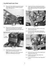
... Figure 2.12 2.13. If the second measurement (spring coils extended) of the forward clutch is too short (less than 3/16"), the tension is correct. 2.9. Troy-Bilt Small Frame Tillers 2.5. Squeeze the forward clutch bail to the upper handlebar. Loosen the hex jam nut securing the clutch cable assembly in position using a 3/8" wrench and...
... Figure 2.12 2.13. If the second measurement (spring coils extended) of the forward clutch is too short (less than 3/16"), the tension is correct. 2.9. Troy-Bilt Small Frame Tillers 2.5. Squeeze the forward clutch bail to the upper handlebar. Loosen the hex jam nut securing the clutch cable assembly in position using a 3/8" wrench and...
Service Manual
Page 7
... cable clockwise (towards the forward clutch bail) to increase tension, or counter-clockwise to the adjustment screw using a 3/8" wrench and a small adjustable wrench. Spark Plug Troy-Bilt Small Frame Tillers 3.2. See Figure 3.2. Tighten the hex jam nut up against the forward clutch cable end using a 3/8" wrench and a small adjustable wrench.
... cable clockwise (towards the forward clutch bail) to increase tension, or counter-clockwise to the adjustment screw using a 3/8" wrench and a small adjustable wrench. Spark Plug Troy-Bilt Small Frame Tillers 3.2. See Figure 3.2. Tighten the hex jam nut up against the forward clutch cable end using a 3/8" wrench and a small adjustable wrench.
Service Manual
Page 8
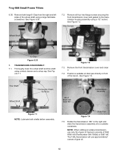
... upper portion of the lower cable mounting bracket. 3.10. Remove the lower portion of the work area. See Figure 3.5. Cable Tie 3.8. See Figure 3.10. Troy-Bilt Small Frame Tillers 3.5. Remove the hex flange screw and large flat washer securing the belt cover to the lower handlebar using side cutters. Figure 3.10 3.11. Hex...
... upper portion of the lower cable mounting bracket. 3.10. Remove the lower portion of the work area. See Figure 3.5. Cable Tie 3.8. See Figure 3.10. Troy-Bilt Small Frame Tillers 3.5. Remove the hex flange screw and large flat washer securing the belt cover to the lower handlebar using side cutters. Figure 3.10 3.11. Hex...
Service Manual
Page 9
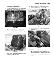
... pulley. DRIVE BELT REPLACEMENT: 4.1. Remove the belt from the transmission pulley. See Figure 4.5. Install the new belt in the reverse order above. Spark Plug Troy-Bilt Small Frame Tillers 4.4. Figure 4.5 4.6. See Figure 4.1. Pivot the belt cover on the forward clutch cable until it to the engine. Perform the Forward Clutch Cable Adjustment section...
... pulley. DRIVE BELT REPLACEMENT: 4.1. Remove the belt from the transmission pulley. See Figure 4.5. Install the new belt in the reverse order above. Spark Plug Troy-Bilt Small Frame Tillers 4.4. Figure 4.5 4.6. See Figure 4.1. Pivot the belt cover on the forward clutch cable until it to the engine. Perform the Forward Clutch Cable Adjustment section...
Service Manual
Page 10
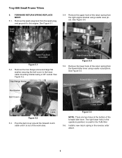
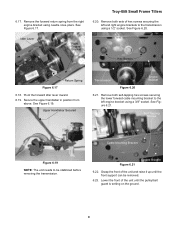
... SPRING REPLACEMENT: 5.1. Remove the spark plug boot from the spark plug, and ground it is used for the Tuffy tiller. 5.6. Remove the upper hook of the return spring from the right engine bracket using needle nose pliers. Pivot the ...6 Hex Flange Screw Flat Washer Belt Cover Return Spring Right Engine Bracket Figure 5.4 5.5. Return Spring Forward Idler Lever Clutch Cable Figure 5.2 5.3. Troy-Bilt Small Frame Tillers 5. See Figure 5.1. Remove the lower hook of the return spring from the forward idler lever using a 3/8" socket. See Figure 5.4. Upper Hook...
... SPRING REPLACEMENT: 5.1. Remove the spark plug boot from the spark plug, and ground it is used for the Tuffy tiller. 5.6. Remove the upper hook of the return spring from the right engine bracket using needle nose pliers. Pivot the ...6 Hex Flange Screw Flat Washer Belt Cover Return Spring Right Engine Bracket Figure 5.4 5.5. Return Spring Forward Idler Lever Clutch Cable Figure 5.2 5.3. Troy-Bilt Small Frame Tillers 5. See Figure 5.1. Remove the lower hook of the return spring from the forward idler lever using a 3/8" socket. See Figure 5.4. Upper Hook...

Service Manual
Page 11
Troy-Bilt Small Frame Tillers 6. Secure the handlebar from the forward idler lever. 6.4. Remove the hex screw, bushing, lock washer and lock nut securing the drag bar to the bottom ...
Troy-Bilt Small Frame Tillers 6. Secure the handlebar from the forward idler lever. 6.4. Remove the hex screw, bushing, lock washer and lock nut securing the drag bar to the bottom ...

Service Manual
Page 12
See Image Below. Cut A Way Wheels off the ground. Cut A Way for Spiral Pin 6.13. Troy-Bilt Small Frame Tillers 6.12. Raise the front of the tiller up until the wheel assemblies are off Ground Raise the Unit Up Figure 6.14 6.15. Lower the unit back onto the tines. Hair Pin Clevis ...
See Image Below. Cut A Way Wheels off the ground. Cut A Way for Spiral Pin 6.13. Troy-Bilt Small Frame Tillers 6.12. Raise the front of the tiller up until the wheel assemblies are off Ground Raise the Unit Up Figure 6.14 6.15. Lower the unit back onto the tines. Hair Pin Clevis ...
Service Manual
Page 13
... Hex Screws Return Spring Figure 6.17 6.18. Upper Handlebar Secured Transmission Figure 6.20 Engine Bracket 6.21. See Figure 6.20. Figure 6.21 Engine Bracket 6.22. Troy-Bilt Small Frame Tillers 6.20. Pivot the forward idler lever inward. 6.19. See Figure 6.17. Lower the front of hex screws securing the left engine bracket using needle...
... Hex Screws Return Spring Figure 6.17 6.18. Upper Handlebar Secured Transmission Figure 6.20 Engine Bracket 6.21. See Figure 6.20. Figure 6.21 Engine Bracket 6.22. Troy-Bilt Small Frame Tillers 6.20. Pivot the forward idler lever inward. 6.19. See Figure 6.17. Lower the front of hex screws securing the left engine bracket using needle...
Service Manual
Page 14
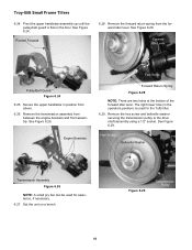
Pivot the upper handlebar assembly up until the pulley/belt guard is used for the Tuffy tiller. 6.29. Figure 6.29 Transmission Pulley 10 Troy-Bilt Small Frame Tillers 6.24. Pivoted Forward 6.28. Remove the forward return spring from between the engine brackets and front assembly. Forward Idle Lever Pulley/Belt Guard Figure 6.24 6....
Pivot the upper handlebar assembly up until the pulley/belt guard is used for the Tuffy tiller. 6.29. Figure 6.29 Transmission Pulley 10 Troy-Bilt Small Frame Tillers 6.24. Pivoted Forward 6.28. Remove the forward return spring from between the engine brackets and front assembly. Forward Idle Lever Pulley/Belt Guard Figure 6.24 6....

Service Manual
Page 15
... Washer Hex Screw Figure 6.30 6.31. NOTE: Record the orientation of the transmission up and set it on a 2" x 4" block. 6.30. Transmission Pulley Key Belleville Troy-Bilt Small Frame Tillers 6.33. See Image Below Left Right Shoulder Washer Lock Washer Hex Screw Figure 6.31 Idler Pulley 6.32. Remove the transmission pulley, key and front...
... Washer Hex Screw Figure 6.30 6.31. NOTE: Record the orientation of the transmission up and set it on a 2" x 4" block. 6.30. Transmission Pulley Key Belleville Troy-Bilt Small Frame Tillers 6.33. See Image Below Left Right Shoulder Washer Lock Washer Hex Screw Figure 6.31 Idler Pulley 6.32. Remove the transmission pulley, key and front...
Service Manual
Page 16
... only GL-4 gear oil having a viscosity of the wheel shaft using contact cleaner and a shop rag. Remove both shafts before assembly. TRANSMISSION DISASSEMBLY: 7.1. Figure 7.2 7.3. Troy-Bilt Small Frame Tillers 6.35. Tine Shaft Wheel Shaft Thoroughly Clean Surfaces GL-4 85W-140 Gear Oil Transmission Assembly Figure 7.1 NOTE: Lubricate both large E-Clips from the right...
... only GL-4 gear oil having a viscosity of the wheel shaft using contact cleaner and a shop rag. Remove both shafts before assembly. TRANSMISSION DISASSEMBLY: 7.1. Figure 7.2 7.3. Troy-Bilt Small Frame Tillers 6.35. Tine Shaft Wheel Shaft Thoroughly Clean Surfaces GL-4 85W-140 Gear Oil Transmission Assembly Figure 7.1 NOTE: Lubricate both large E-Clips from the right...
Service Manual
Page 17
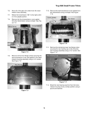
... assembly using a 1/2" socket. Rear Bearing Cap Transmission Overlap Point Rear Transmission Cover Figure 7.9 Short Hex Flange Screw Figure 7.11 7.12. Wheel Worm Cover Gasket Troy-Bilt Small Frame Tillers 7.10. Remove all of the gear oil to the right until it is in the upright position. 7.8. Remove the front transmission cover gasket from...
... assembly using a 1/2" socket. Rear Bearing Cap Transmission Overlap Point Rear Transmission Cover Figure 7.9 Short Hex Flange Screw Figure 7.11 7.12. Wheel Worm Cover Gasket Troy-Bilt Small Frame Tillers 7.10. Remove all of the gear oil to the right until it is in the upright position. 7.8. Remove the front transmission cover gasket from...

Service Manual
Page 18
... sealant and gasket (if used for the drive shaft assembly. 7.15. Sealant 7.18. Do not us a hammer. 14 NOTE: This is a rear bearing cap gasket. Troy-Bilt Small Frame Tillers 7.13. See Figure 7.13. Slowly push the drive shaft assembly rearward and out of the drive shaft. 7.21.
... sealant and gasket (if used for the drive shaft assembly. 7.15. Sealant 7.18. Do not us a hammer. 14 NOTE: This is a rear bearing cap gasket. Troy-Bilt Small Frame Tillers 7.13. See Figure 7.13. Slowly push the drive shaft assembly rearward and out of the drive shaft. 7.21.
Service Manual
Page 19
Troy-Bilt Small Frame Tillers 7.23. Set the transmission assembly into the jaws of protective material into the center of the transmission housing for wear or damage inside the transmission ...
Troy-Bilt Small Frame Tillers 7.23. Set the transmission assembly into the jaws of protective material into the center of the transmission housing for wear or damage inside the transmission ...
Service Manual
Page 20
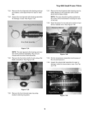
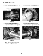
... left sides of the wheel shaft using a small hook tool and a stick magnet. See Figure 7.32. See Figure 7.34. Tiller Shaft Worm Gear Bronze Bushing Spacer Retaining Ring Figure 7.31 Spacer Bronze Bushing 7.32. Wheel Shaft Figure 7.33 7.34. Oil Seal...damaged during removal. Remove the external shims from the transmission housing, at the wheel shaft, using medium retaining ring pliers. Troy-Bilt Small Frame Tillers 7.31. Inspect the tiller shaft assembly for wear or damage inside the transmission case. Wheel Shaft Figure 7.34 External Shims 16 See Figure 7.33...
... left sides of the wheel shaft using a small hook tool and a stick magnet. See Figure 7.32. See Figure 7.34. Tiller Shaft Worm Gear Bronze Bushing Spacer Retaining Ring Figure 7.31 Spacer Bronze Bushing 7.32. Wheel Shaft Figure 7.33 7.34. Oil Seal...damaged during removal. Remove the external shims from the transmission housing, at the wheel shaft, using medium retaining ring pliers. Troy-Bilt Small Frame Tillers 7.31. Inspect the tiller shaft assembly for wear or damage inside the transmission case. Wheel Shaft Figure 7.34 External Shims 16 See Figure 7.33...


