
Operation Manual
Page 2
...equipment. Choose from the options below: ◊ Visit us directly. It instructs you how to right and left side of the tine shield. All information in personal injury or property damage. Please be found at the front right corner of the machine are observed ...Thank you for more information. Characteristics and features discussed and/or illustrated in the provided area to ensure your machine, for purchasing a Troy-Bilt Tiller. If you have difficulty assembling this product or have any questions regarding the controls, operation, or maintenance of the engine equipped on ...
...equipment. Choose from the options below: ◊ Visit us directly. It instructs you how to right and left side of the tine shield. All information in personal injury or property damage. Please be found at the front right corner of the machine are observed ...Thank you for more information. Characteristics and features discussed and/or illustrated in the provided area to ensure your machine, for purchasing a Troy-Bilt Tiller. If you have difficulty assembling this product or have any questions regarding the controls, operation, or maintenance of the engine equipped on ...
Operation Manual
Page 4
...Be careful when tilling in this machine without good visibility or light. After striking a foreign object, stop the engine and make certain the tines and all cigarettes, cigars, pipes and other sources of grass, leaves, or other gas appliances. Maintenance & Storage 1. Check their proper operation... Exercise caution to prevent unintended starting and operating. 12. Never run an engine indoors or in the ground and propel the tiller forward. If the machine should start making any damage. The governor controls the maximum safe operating speed of you nearest servicing...
...Be careful when tilling in this machine without good visibility or light. After striking a foreign object, stop the engine and make certain the tines and all cigarettes, cigars, pipes and other sources of grass, leaves, or other gas appliances. Maintenance & Storage 1. Check their proper operation... Exercise caution to prevent unintended starting and operating. 12. Never run an engine indoors or in the ground and propel the tiller forward. If the machine should start making any damage. The governor controls the maximum safe operating speed of you nearest servicing...
Operation Manual
Page 8
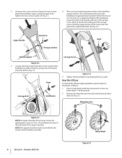
...move, loosen the attaching hex screws (5⁄16-18 x .75) and flange lock nuts (5⁄1618) at approximately waist level when the tines are three height adjustment holes in the handlebar support bracket. See Fig. 3-4. Loosely attach the support brackets to the outside of the screw ...Support Carriage Screw Figure 3-2 3. Refer to the outside of the support brackets. See Fig. 3-5. Tighten the two screws securely. Move Tiller Off Crate To roll the tiller off the ground. 2. Wheel Drive Pin Figure 3-3 NOTE: If a support bracket will position the handlebars at the base of the ...
...move, loosen the attaching hex screws (5⁄16-18 x .75) and flange lock nuts (5⁄1618) at approximately waist level when the tines are three height adjustment holes in the handlebar support bracket. See Fig. 3-4. Loosely attach the support brackets to the outside of the screw ...Support Carriage Screw Figure 3-2 3. Refer to the outside of the support brackets. See Fig. 3-5. Tighten the two screws securely. Move Tiller Off Crate To roll the tiller off the ground. 2. Wheel Drive Pin Figure 3-3 NOTE: If a support bracket will position the handlebars at the base of the ...
Operation Manual
Page 10
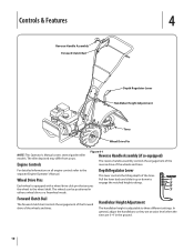
... clutch bail controls the engagement of the forward drive of the wheels and tines. Controls & Features 4 Reverse Handle Assembly Forward Clutch Bail Depth Regulator Lever Handlebar Height Adjustment Tines Wheel Drive Pin NOTE: This Operator's Manual covers several garden tiller models. Wheel Drive Pins Each wheel is adjustable to the wheel shaft. Depth...
... clutch bail controls the engagement of the forward drive of the wheels and tines. Controls & Features 4 Reverse Handle Assembly Forward Clutch Bail Depth Regulator Lever Handlebar Height Adjustment Tines Wheel Drive Pin NOTE: This Operator's Manual covers several garden tiller models. Wheel Drive Pins Each wheel is adjustable to the wheel shaft. Depth...
Operation Manual
Page 11
... regulator lever (A) and lift up or down to the directions in FREEWHEEL, they do not hold back the tiller and the tines could cause loss of the controls on the tiller. 5. Release all the safety guards and covers are in the separate Engine Operator's Manual. Start the engine ... the first five (5) hours of new operation (see Maintenance & Adjustments Section in the wheel drive position before using the tiller controls without the tines engaging the soil (put tines in the garden. Put the wheels in the WHEEL DRIVE position (wheel pins must be in place. 6. Introduction Read...
... regulator lever (A) and lift up or down to the directions in FREEWHEEL, they do not hold back the tiller and the tines could cause loss of the controls on the tiller. 5. Release all the safety guards and covers are in the separate Engine Operator's Manual. Start the engine ... the first five (5) hours of new operation (see Maintenance & Adjustments Section in the wheel drive position before using the tiller controls without the tines engaging the soil (put tines in the garden. Put the wheels in the WHEEL DRIVE position (wheel pins must be in place. 6. Introduction Read...

Operation Manual
Page 12
... till near buried electric cables, telephone lines, pipes or hoses. • This is a CRT (counter-rotating tine) tiller. Then lift the handlebar until the tines are off the wheels and reduces traction. This "fishtailing" action often clears the tines of debris. • If tangling occurs, lift the tines out of the tiller. Walk behind and exercise caution when...
... till near buried electric cables, telephone lines, pipes or hoses. • This is a CRT (counter-rotating tine) tiller. Then lift the handlebar until the tines are off the wheels and reduces traction. This "fishtailing" action often clears the tines of debris. • If tangling occurs, lift the tines out of the tiller. Walk behind and exercise caution when...
Operation Manual
Page 13
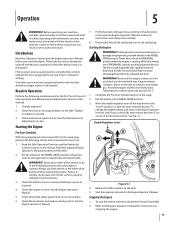
...8226; If the garden size will passes to thoroughly pulverize the soil.) attempt to propel the tiller backward, towards the operator. • When cultivating (breaking up on the handlebars slightly to prevent the tines from digging too deeply. (Cultivating on the rest of the passes. best results (in the... on a regular basis not only eliminates weeds, it may take three or four Without the wheels to hold the tiller back, the tines will not permit lengthwise and then crosswise tilling, overlap the first passes by one -quarter width. Figure 5-4 Suggested Tilling Patterns 1 2 • ...
...8226; If the garden size will passes to thoroughly pulverize the soil.) attempt to propel the tiller backward, towards the operator. • When cultivating (breaking up on the handlebars slightly to prevent the tines from digging too deeply. (Cultivating on the rest of the passes. best results (in the... on a regular basis not only eliminates weeds, it may take three or four Without the wheels to hold the tiller back, the tines will not permit lengthwise and then crosswise tilling, overlap the first passes by one -quarter width. Figure 5-4 Suggested Tilling Patterns 1 2 • ...
Operation Manual
Page 15
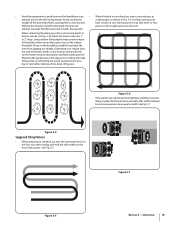
... should be between 15-20 PSI. Handlebar Attaching Screws Depth Regulator Lever Wheel Shaft Tine Shaft Figure 6-1 15 Maintenance Engine Refer to the Engine Operator's Manual packed with your tiller for loose or missing hardware after every 10 operating hours and tighten or replace (... Check Motor Oil Level PP Clean Engine P P Check Drive Belt Tension P P Check Nuts and Bolts P P Lubricate Tiller P Check Gear Oil Level in Transmission P Check Tines for all engine maintenance. Before inspecting, cleaning or servicing the machine, shut off the engine, wait for Wear P Check...
... should be between 15-20 PSI. Handlebar Attaching Screws Depth Regulator Lever Wheel Shaft Tine Shaft Figure 6-1 15 Maintenance Engine Refer to the Engine Operator's Manual packed with your tiller for loose or missing hardware after every 10 operating hours and tighten or replace (... Check Motor Oil Level PP Clean Engine P P Check Drive Belt Tension P P Check Nuts and Bolts P P Lubricate Tiller P Check Gear Oil Level in Transmission P Check Tines for all engine maintenance. Before inspecting, cleaning or servicing the machine, shut off the engine, wait for Wear P Check...
Operation Manual
Page 16
Apply grease to protect the fuel lines, carburetor and fuel tank from the transmission housing and look inside the oil fill hole to gently remove any oil leak. Off-Season Storage When the tiller won't be used for an extended period, prepare it reaches the halfway point on the drive shaft.... way up the side of the depth regulator lever. • Remove the tines and clean the tine shaft. To Check the Transmission Gear Oil Level: 1. Gear oil will expand in the Engine Operator's Manual. With the tiller on oil can result in the shaft). Protect the engine and perform recommended...
Apply grease to protect the fuel lines, carburetor and fuel tank from the transmission housing and look inside the oil fill hole to gently remove any oil leak. Off-Season Storage When the tiller won't be used for an extended period, prepare it reaches the halfway point on the drive shaft.... way up the side of the depth regulator lever. • Remove the tines and clean the tine shaft. To Check the Transmission Gear Oil Level: 1. Gear oil will expand in the Engine Operator's Manual. With the tiller on oil can result in the shaft). Protect the engine and perform recommended...
Operation Manual
Page 17
...belt needs to be replaced, see your local authorized dealer or refer to the Replacement Parts Section for rust, rough spots or burrs. Tine Inspection With use and should be sure to fall under organic matter. Install each tilling season and after every 30 operating hours. Drain... it has been contaminated with use , the tines will enter the soil first when the tiller moves forward. If removing both tine assemblies, mark them "left side of grease to the tine shaft. If needed . Use only a factory-authorized belt as the tiller moves forward. the-counter" belt may not ...
...belt needs to be replaced, see your local authorized dealer or refer to the Replacement Parts Section for rust, rough spots or burrs. Tine Inspection With use and should be sure to fall under organic matter. Install each tilling season and after every 30 operating hours. Drain... it has been contaminated with use , the tines will enter the soil first when the tiller moves forward. If removing both tine assemblies, mark them "left side of grease to the tine shaft. If needed . Use only a factory-authorized belt as the tiller moves forward. the-counter" belt may not ...

Service Manual
Page 5
... the Engine Owner's Manual for - Measure the overall length of the coils on the for more information. 2. Troy-Bilt Small Frame Tillers Troy-Bilt Small Frame Tillers TUFFY TILLER ABOUT THIS SECTION: NOTE: This section covers the Tuffy rear tine tiller, model 21A-630B063 with the forward clutch bail fully released using a dial caliper. Record the forward clutch spring...
... the Engine Owner's Manual for - Measure the overall length of the coils on the for more information. 2. Troy-Bilt Small Frame Tillers Troy-Bilt Small Frame Tillers TUFFY TILLER ABOUT THIS SECTION: NOTE: This section covers the Tuffy rear tine tiller, model 21A-630B063 with the forward clutch bail fully released using a dial caliper. Record the forward clutch spring...

Service Manual
Page 11
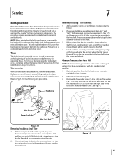
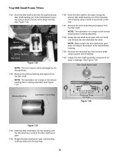
Troy-Bilt Small Frame Tillers 6. Grasp the upper handlebar and pivot the unit NOTE: Perform the Drive Belt Replacement sec- Remove Drive Belt 6.1. Set the belt cover aside. 6.6. Remove both self tapping hex flange screws securing the tine hood to the right and left hood brackets using a 1/2" socket. performing this section. See Image Below 6.9. Pivot...
Troy-Bilt Small Frame Tillers 6. Grasp the upper handlebar and pivot the unit NOTE: Perform the Drive Belt Replacement sec- Remove Drive Belt 6.1. Set the belt cover aside. 6.6. Remove both self tapping hex flange screws securing the tine hood to the right and left hood brackets using a 1/2" socket. performing this section. See Image Below 6.9. Pivot...

Service Manual
Page 12
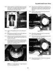
Troy-Bilt Small Frame Tillers 6.12. See Image Below. Remove both hair pins and clevis pins securing the wheel...Way Wheels off the ground. Remove both wheel assemblies. 8 NOTE: Make certain the unit is a cut a way in the tine hood to allow the depth bar's spiral pin to pass through. Remove the depth regulator assembly and drag bar assembly. Raise ... Up Figure 6.14 6.15. See Figure 6.15. Lower the unit back onto the tines. Hood Brackets Drag Bar Figure 6.12 NOTE: There is resting on the tines and not on the trailing shield. Cut A Way for Spiral Pin 6.13. Hair...
Troy-Bilt Small Frame Tillers 6.12. See Image Below. Remove both hair pins and clevis pins securing the wheel...Way Wheels off the ground. Remove both wheel assemblies. 8 NOTE: Make certain the unit is a cut a way in the tine hood to allow the depth bar's spiral pin to pass through. Remove the depth regulator assembly and drag bar assembly. Raise ... Up Figure 6.14 6.15. See Figure 6.15. Lower the unit back onto the tines. Hood Brackets Drag Bar Figure 6.12 NOTE: There is resting on the tines and not on the trailing shield. Cut A Way for Spiral Pin 6.13. Hair...

Service Manual
Page 15
... set it on a 2" x 4" block. Forward Lever 2" x 4" Figure 6.33 6.34. 6.30. Transmission Pulley Key Belleville Troy-Bilt Small Frame Tillers 6.33. See Figure 6.33. See Figure 6.31. Remove the hex screws and lock nuts securing the right and left tine assemblies using a 1/2" socket. Remove the transmission pulley, key and front support washer from the drive...
... set it on a 2" x 4" block. Forward Lever 2" x 4" Figure 6.33 6.34. 6.30. Transmission Pulley Key Belleville Troy-Bilt Small Frame Tillers 6.33. See Figure 6.33. See Figure 6.31. Remove the hex screws and lock nuts securing the right and left tine assemblies using a 1/2" socket. Remove the transmission pulley, key and front support washer from the drive...
Service Manual
Page 16
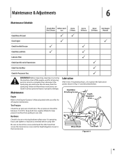
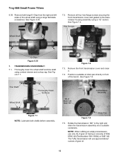
Troy-Bilt Small Frame Tillers 6.35. See Figure 6.35. 7.2. Remove all four hex flange screws securing the front transmission cover and gasket to the right and drain the transmission assembly ... in front of gear oil. 12 ounces of the bench. See Figure 7.1. Thoroughly clean the wheel shaft and tine shaft using a large flat blade screwdriver. Figure 7.2 7.3. Drain Pan Figure 7.4 7.5. Remove both shafts before assembly. Tine Shaft Wheel Shaft Thoroughly Clean Surfaces GL-4 85W-140 Gear Oil Transmission Assembly Figure 7.1 NOTE: Lubricate both...
Troy-Bilt Small Frame Tillers 6.35. See Figure 6.35. 7.2. Remove all four hex flange screws securing the front transmission cover and gasket to the right and drain the transmission assembly ... in front of gear oil. 12 ounces of the bench. See Figure 7.1. Thoroughly clean the wheel shaft and tine shaft using a large flat blade screwdriver. Figure 7.2 7.3. Drain Pan Figure 7.4 7.5. Remove both shafts before assembly. Tine Shaft Wheel Shaft Thoroughly Clean Surfaces GL-4 85W-140 Gear Oil Transmission Assembly Figure 7.1 NOTE: Lubricate both...
Service Manual
Page 17
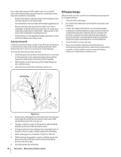
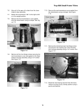
... hammer. 13 See Figure 7.10. See Figure 7.11. Break the rear bearing cap free from the transmission using a scraper. Cover Gasket Tine Worm Figure 7.8 7.9. See Figure 7.9. Rotate the transmission 180° to the transmission housing assembly using a 1/2" socket. Remove the front ...Bearing Cap Transmission Overlap Point Rear Transmission Cover Figure 7.9 Short Hex Flange Screw Figure 7.11 7.12. Wheel Worm Cover Gasket Troy-Bilt Small Frame Tillers 7.10. Remove the remaining lower hex flange screw securing the rear bearing cap to the right until it is in the ...
... hammer. 13 See Figure 7.10. See Figure 7.11. Break the rear bearing cap free from the transmission using a scraper. Cover Gasket Tine Worm Figure 7.8 7.9. See Figure 7.9. Rotate the transmission 180° to the transmission housing assembly using a 1/2" socket. Remove the front ...Bearing Cap Transmission Overlap Point Rear Transmission Cover Figure 7.9 Short Hex Flange Screw Figure 7.11 7.12. Wheel Worm Cover Gasket Troy-Bilt Small Frame Tillers 7.10. Remove the remaining lower hex flange screw securing the rear bearing cap to the right until it is in the ...
Service Manual
Page 23
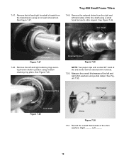
...47. Remove the left and right shim washers using medium retaining ring pliers. See Figure 7.50. Oil Seal Troy-Bilt Small Frame Tillers 7.49. See Figure 7.48. Retaining Ring Dial Caliper Tine Shaft Figure 7.48 Shims Figure 7.50 7.51. Remove the external shims from the right and left and right... tine shaft oil seals from the transmission using a small hook tool and a stick magnet. 7.47. Remove the ...
...47. Remove the left and right shim washers using medium retaining ring pliers. See Figure 7.50. Oil Seal Troy-Bilt Small Frame Tillers 7.49. See Figure 7.48. Retaining Ring Dial Caliper Tine Shaft Figure 7.48 Shims Figure 7.50 7.51. Remove the external shims from the right and left and right... tine shaft oil seals from the transmission using a small hook tool and a stick magnet. 7.47. Remove the ...
Service Manual
Page 24
...Cut A Way 7.56. Remove the bronze bushing and spacer from the tiller shaft. Grasp the tine shaft worm gear with one hand, and remove the tine shaft with the other. See Figure 7.60. Slide the tiller shaft back into the housing until the Woodruff key slides into the key... tine shaft worm gear does not drop to the left, forcing the bronze tiller shaft bushing out of the transmission housing using a block of the transmission housing. 7.59. Rotate the tiller shaft worm gear until the Woodruff key contacts the tiller shaft worm gear. 7.55. See Figure 7.53. Troy-Bilt Small Frame Tillers...
...Cut A Way 7.56. Remove the bronze bushing and spacer from the tiller shaft. Grasp the tine shaft worm gear with one hand, and remove the tine shaft with the other. See Figure 7.60. Slide the tiller shaft back into the housing until the Woodruff key slides into the key... tine shaft worm gear does not drop to the left, forcing the bronze tiller shaft bushing out of the transmission housing using a block of the transmission housing. 7.59. Rotate the tiller shaft worm gear until the Woodruff key contacts the tiller shaft worm gear. 7.55. See Figure 7.53. Troy-Bilt Small Frame Tillers...

Service Manual
Page 32
... the inside of the Wheel Shaft Seal 8.64. Drive the wheel shaft seal into the tine shaft using a bushing driver and hammer. Lubricate the right and left sides of the tine shaft bronze bushing that has been installed. 28 Transmission Housing Bronze Bushing Flush Figure 8.66 ...tine shaft's bronze bushings into the transmission housing as far as a bushing installation tool. 8.67. Position one of the wheel shaft oil seals over one of the Wheel Shaft Seal Figure 8.58 8.59. Woodruff Key Tine Shaft Figure 8.67 8.68. See Figure 8.66. See Figure 8.58. Troy-Bilt Small Frame Tillers...
... the inside of the Wheel Shaft Seal 8.64. Drive the wheel shaft seal into the tine shaft using a bushing driver and hammer. Lubricate the right and left sides of the tine shaft bronze bushing that has been installed. 28 Transmission Housing Bronze Bushing Flush Figure 8.66 ...tine shaft's bronze bushings into the transmission housing as far as a bushing installation tool. 8.67. Position one of the wheel shaft oil seals over one of the Wheel Shaft Seal Figure 8.58 8.59. Woodruff Key Tine Shaft Figure 8.67 8.68. See Figure 8.66. See Figure 8.58. Troy-Bilt Small Frame Tillers...
Service Manual
Page 33
... hammer. Spacer Spacer Bronze Bushing Troy-Bilt Small Frame Tillers 8.74. Position a dial indicator at one side and zero in . 8.73. Tine Shaft Worm Gear Figure 8.69 8.70. Pull Tine Shaft Out Dial Indicator Figure 8.75 8.76. Drive the first tine shaft bronze bushing into the installed tine shaft bronze bushing. Pull Tine Shaft In Flush Bronze Bushing...
... hammer. Spacer Spacer Bronze Bushing Troy-Bilt Small Frame Tillers 8.74. Position a dial indicator at one side and zero in . 8.73. Tine Shaft Worm Gear Figure 8.69 8.70. Pull Tine Shaft Out Dial Indicator Figure 8.75 8.76. Drive the first tine shaft bronze bushing into the installed tine shaft bronze bushing. Pull Tine Shaft In Flush Bronze Bushing...


