
Operation Manual
Page 2
...model plate by standing at the operator's position and looking down at (800) 828-5500 or (330) 558-7220 ◊ Write to Troy-Bilt LLC • P.O. If you seek technical support via our web site, Customer Support Department, or with regards to performance, power-rating, ...web at www.troybilt.com See How-to Maintenance and Parts Installation Videos at www.troybilt.com/tutorials ◊ Call a Customer Support Representative at the front right corner of this manual is responsible for purchasing a Troy-Bilt Tiller. Choose from the operating position The engine manufacturer is ...
...model plate by standing at the operator's position and looking down at (800) 828-5500 or (330) 558-7220 ◊ Write to Troy-Bilt LLC • P.O. If you seek technical support via our web site, Customer Support Department, or with regards to performance, power-rating, ...web at www.troybilt.com See How-to Maintenance and Parts Installation Videos at www.troybilt.com/tutorials ◊ Call a Customer Support Representative at the front right corner of this manual is responsible for purchasing a Troy-Bilt Tiller. Choose from the operating position The engine manufacturer is ...
Operation Manual
Page 4
...ventilated area. Stay alert for damage. Repair the damage before refueling. Never run an engine indoors or in the ground and propel the tiller forward. Never pick up . Failure to no more than from the machine while it off the engine and equipment. Contact Customer Support ... speeds on or crossing gravel surfaces. Check bolts and screws for important details if the machine is running . Never tamper with the rotating parts can result in contact with a portable container, rather than ½ inch below bottom of ignition. When practical, remove gas-powered equipment...
...ventilated area. Stay alert for damage. Repair the damage before refueling. Never run an engine indoors or in the ground and propel the tiller forward. Never pick up . Failure to no more than from the machine while it off the engine and equipment. Contact Customer Support ... speeds on or crossing gravel surfaces. Check bolts and screws for important details if the machine is running . Never tamper with the rotating parts can result in contact with a portable container, rather than ½ inch below bottom of ignition. When practical, remove gas-powered equipment...

Operation Manual
Page 7
... to do not attempt to remove it from the carton. Assembly Unpacking Instructions NOTE: While unpacking, do not start the engine until all loose parts from the shipping platform until instructed to the Engine Operator's Manual for Assembly • Two 1⁄2" open-end wrenches • Block of ...wood (to the right or left side of the tiller are from the operator's position. 1. Remove all assembly steps are missing or damaged). WARNING! Assembly & Set-Up 3 Contents of the control cables....
... to do not attempt to remove it from the carton. Assembly Unpacking Instructions NOTE: While unpacking, do not start the engine until all loose parts from the shipping platform until instructed to the Engine Operator's Manual for Assembly • Two 1⁄2" open-end wrenches • Block of ...wood (to the right or left side of the tiller are from the operator's position. 1. Remove all assembly steps are missing or damaged). WARNING! Assembly & Set-Up 3 Contents of the control cables....

Operation Manual
Page 12
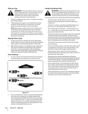
...with reverse handle: • Look behind and a little to stop reversing, let go of the soil and run the tiller in reverse. • Stop all moving parts to one hand, palm up against the ground. Engage Drive & Tines 1. On models with one hand, yet keep your.... See Fig. 5-3. 3. WARNING! Before tilling, contact your property. Do not till near buried electric cables, telephone lines, pipes or hoses. • This is a CRT (counter-rotating tine) tiller. This creates an "uppercut" tine action which could result in reverse: a. On later passes, the wheels may become...
...with reverse handle: • Look behind and a little to stop reversing, let go of the soil and run the tiller in reverse. • Stop all moving parts to one hand, palm up against the ground. Engage Drive & Tines 1. On models with one hand, yet keep your.... See Fig. 5-3. 3. WARNING! Before tilling, contact your property. Do not till near buried electric cables, telephone lines, pipes or hoses. • This is a CRT (counter-rotating tine) tiller. This creates an "uppercut" tine action which could result in reverse: a. On later passes, the wheels may become...
Operation Manual
Page 14
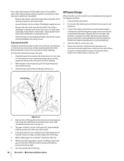
... (if necessary), and to lift the handlebars slightly while going down ramps, walk backward with blocks and securely tie the tiller down ramps tiller-first, as this can starve engine parts of you. Keep the motor oil level at the full point at each side to the ramp, the better). Two ...or more of the downhill outside edge of the tiller. Have a person at all parts to stop the tiller from its parking brake. • When going uphill than terracing. Keep alert for safe operation. Also, use the blocks to...
... (if necessary), and to lift the handlebars slightly while going down ramps, walk backward with blocks and securely tie the tiller down ramps tiller-first, as this can starve engine parts of you. Keep the motor oil level at the full point at each side to the ramp, the better). Two ...or more of the downhill outside edge of the tiller. Have a person at all parts to stop the tiller from its parking brake. • When going uphill than terracing. Keep alert for safe operation. Also, use the blocks to...
Operation Manual
Page 15
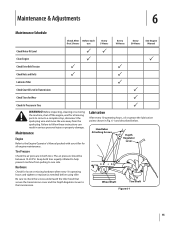
...Every 30 Hours See Engine Manual Check Motor Oil Level PP Clean Engine P P Check Drive Belt Tension P P Check Nuts and Bolts P P Lubricate Tiller P Check Gear Oil Level in Transmission P Check Tines for Wear P Check Air Pressure in both tires equally inflated to help prevent machine from the spark... air pressure should be between 15-20 PSI. Before inspecting, cleaning or servicing the machine, shut off the engine, wait for all moving parts to come to a complete stop, disconnect the spark plug wire and move the wire away from pulling to one side. Hardware Check for loose...
...Every 30 Hours See Engine Manual Check Motor Oil Level PP Clean Engine P P Check Drive Belt Tension P P Check Nuts and Bolts P P Lubricate Tiller P Check Gear Oil Level in Transmission P Check Tines for Wear P Check Air Pressure in both tires equally inflated to help prevent machine from the spark... air pressure should be between 15-20 PSI. Before inspecting, cleaning or servicing the machine, shut off the engine, wait for all moving parts to come to a complete stop, disconnect the spark plug wire and move the wire away from pulling to one side. Hardware Check for loose...
Operation Manual
Page 16
...extended period, prepare it reaches the halfway point on oil can result in the Engine Operator's Manual. Off-Season Storage When the tiller won't be used for loose parts and hardware. 3. Transmission Gear Oil Check the transmission gear oil after every 30 hours of the main drive shaft. 6. Be ...sure to protect the fuel lines, carburetor and fuel tank from the transmission housing and look inside the oil fill hole to locate the...
...extended period, prepare it reaches the halfway point on oil can result in the Engine Operator's Manual. Off-Season Storage When the tiller won't be used for loose parts and hardware. 3. Transmission Gear Oil Check the transmission gear oil after every 30 hours of the main drive shaft. 6. Be ...sure to protect the fuel lines, carburetor and fuel tank from the transmission housing and look inside the oil fill hole to locate the...
Operation Manual
Page 17
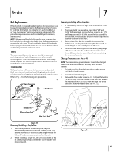
...and locknut. Lightly file or sand, as an "over- See Fig. 7-2. When installing a single tine, be replaced either individually or as the tiller moves forward. Use only a factory-authorized belt as needed , use and should be sure to the shaft. 4. Tine Inspection With use a ...eight tines mounted on the nuts. 2. Tines The bolo tines will enter the soil first when the tiller moves forward. Before reinstalling the tine assembly, inspect the tine shaft for tine identification and part numbers. Remove the hex washer screw (1⁄4-20 x .500) and flat washer (.28 x .74...
...and locknut. Lightly file or sand, as an "over- See Fig. 7-2. When installing a single tine, be replaced either individually or as the tiller moves forward. Use only a factory-authorized belt as needed , use and should be sure to the shaft. 4. Tine Inspection With use a ...eight tines mounted on the nuts. 2. Tines The bolo tines will enter the soil first when the tiller moves forward. Before reinstalling the tine assembly, inspect the tine shaft for tine identification and part numbers. Remove the hex washer screw (1⁄4-20 x .500) and flat washer (.28 x .74...
Operation Manual
Page 24
... mulch kits. C Attachments - Refer to obtain warranty coverage. No other peril or natural disaster. Troy-Bilt shall not be greater than an authorized service dealer. You assume the risk and liability for the life of the tiller, to the parts as set forth in the following cases: a. This limited warranty shall only apply if...
... mulch kits. C Attachments - Refer to obtain warranty coverage. No other peril or natural disaster. Troy-Bilt shall not be greater than an authorized service dealer. You assume the risk and liability for the life of the tiller, to the parts as set forth in the following cases: a. This limited warranty shall only apply if...
Service Manual
Page 16
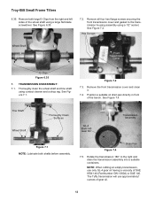
...° to the transmission housing assembly using contact cleaner and a shop rag. Remove the front transmission cover and clean it. 7.4. Troy-Bilt Small Frame Tillers 6.35. Remove both shafts before assembly. Figure 7.2 7.3. Hex Screws Wheel Shaft Front Transmission Cover E-Clips Figure 6.35 7. See ...Figure 7.2. Position a suitable oil drain pan directly in front of SAE 85W-140 (Part Number GW-1360A) or SAE 140. Drain ...
...° to the transmission housing assembly using contact cleaner and a shop rag. Remove the front transmission cover and clean it. 7.4. Troy-Bilt Small Frame Tillers 6.35. Remove both shafts before assembly. Figure 7.2 7.3. Hex Screws Wheel Shaft Front Transmission Cover E-Clips Figure 6.35 7. See ...Figure 7.2. Position a suitable oil drain pan directly in front of SAE 85W-140 (Part Number GW-1360A) or SAE 140. Drain ...


