
Operation Manual
Page 1
Printed In USA TROY-BILT LLC, P.O. BOX 361131 CLEVELAND, OHIO 44136-0019 Form No. 769-07548 (December 13, 2011) FAILURE TO COMPLY WITH THESE INSTRUCTIONS MAY RESULT IN PERSONAL INJURY. Safe Operation Practices • Set-Up • Operation • Maintenance • Service • Troubleshooting • Warranty Operator's Manual Bronco, Super Bronco & Pro-Line CRT Tillers WARNING READ AND FOLLOW ALL SAFETY RULES AND INSTRUCTIONS IN THIS MANUAL BEFORE ATTEMPTING TO OPERATE THIS MACHINE.
Printed In USA TROY-BILT LLC, P.O. BOX 361131 CLEVELAND, OHIO 44136-0019 Form No. 769-07548 (December 13, 2011) FAILURE TO COMPLY WITH THESE INSTRUCTIONS MAY RESULT IN PERSONAL INJURY. Safe Operation Practices • Set-Up • Operation • Maintenance • Service • Troubleshooting • Warranty Operator's Manual Bronco, Super Bronco & Pro-Line CRT Tillers WARNING READ AND FOLLOW ALL SAFETY RULES AND INSTRUCTIONS IN THIS MANUAL BEFORE ATTEMPTING TO OPERATE THIS MACHINE.

Operation Manual
Page 2
... Please be aware that you, and any other persons who will be found on this manual is responsible for purchasing a Troy-Bilt Tiller. Throughout this product or have difficulty assembling this manual, all references to the retailer or dealer without incurring obligation. All information... in the provided area to Troy-Bilt LLC • P.O. Table of the machine are observed from the options below: ◊ Visit us directly. Model Number Serial...
... Please be aware that you, and any other persons who will be found on this manual is responsible for purchasing a Troy-Bilt Tiller. Throughout this product or have difficulty assembling this manual, all references to the retailer or dealer without incurring obligation. All information... in the provided area to Troy-Bilt LLC • P.O. Table of the machine are observed from the options below: ◊ Visit us directly. Model Number Serial...
Operation Manual
Page 24
HOW TO OBTAIN SERVICE: Warranty service is available, WITH PROOF OF PURCHASE, through Troy-Bilt's authorized channels of the tiller, to be liable for incidental or consequential loss or damage including, without limitation, expenses incurred for substitute or...; This limited warranty shall only apply if this product for products sold . Transmission - Attachments - b. Attachments include, but are not genuine Troy-Bilt parts. Check your warranty as described below is repair or replacement of the product as identified. These items may also have a separate oneyear ...
HOW TO OBTAIN SERVICE: Warranty service is available, WITH PROOF OF PURCHASE, through Troy-Bilt's authorized channels of the tiller, to be liable for incidental or consequential loss or damage including, without limitation, expenses incurred for substitute or...; This limited warranty shall only apply if this product for products sold . Transmission - Attachments - b. Attachments include, but are not genuine Troy-Bilt parts. Check your warranty as described below is repair or replacement of the product as identified. These items may also have a separate oneyear ...

Service Manual
Page 1
Service Manual Small Frame Troy-Bilt Tillers MTD Products LLC - Product Training and Education Department FORM NUMBER 769-01529 11/2004
Service Manual Small Frame Troy-Bilt Tillers MTD Products LLC - Product Training and Education Department FORM NUMBER 769-01529 11/2004

Service Manual
Page 5
Troy-Bilt Small Frame Tillers Troy-Bilt Small Frame Tillers TUFFY TILLER ABOUT THIS SECTION: NOTE: This section covers the Tuffy rear tine tiller, model 21A-630B063 with the forward clutch bail fully released using a dial caliper. See Figure 2.1. Measure the overall length of the coils on the for ... the spark plug boot from the spark plug, and ground it to 6" • 10" Agricultural Tires 1. Make certain the forward clutch bail is powering the tiller, and refer to follow along with the Troy-Bilt Factory School.
Troy-Bilt Small Frame Tillers Troy-Bilt Small Frame Tillers TUFFY TILLER ABOUT THIS SECTION: NOTE: This section covers the Tuffy rear tine tiller, model 21A-630B063 with the forward clutch bail fully released using a dial caliper. See Figure 2.1. Measure the overall length of the coils on the for ... the spark plug boot from the spark plug, and ground it to 6" • 10" Agricultural Tires 1. Make certain the forward clutch bail is powering the tiller, and refer to follow along with the Troy-Bilt Factory School.

Service Manual
Page 6
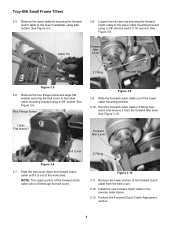
... Upper Handle Figure 2.5 2.6. If the second measurement (spring coils extended) of the forward clutch is too short (less than 3/16"), the tension is correct. 2.9. Troy-Bilt Small Frame Tillers 2.5. Loosen the hex jam nut securing the clutch cable assembly in position using a 3/8" wrench and a small adjustable wrench. Continue through this section. 2.11. If...
... Upper Handle Figure 2.5 2.6. If the second measurement (spring coils extended) of the forward clutch is too short (less than 3/16"), the tension is correct. 2.9. Troy-Bilt Small Frame Tillers 2.5. Loosen the hex jam nut securing the clutch cable assembly in position using a 3/8" wrench and a small adjustable wrench. Continue through this section. 2.11. If...
Service Manual
Page 7
... the forward clutch cable end from the adjustment screw by rotating it to the adjustment screw using a 3/8" wrench and a small adjustable wrench. Spark Plug Troy-Bilt Small Frame Tillers 3.2. Remove the forward clutch cable from the forward clutch bail). 3.4. Tighten the hex jam nut up against the forward clutch cable end using a 3/8" wrench...
... the forward clutch cable end from the adjustment screw by rotating it to the adjustment screw using a 3/8" wrench and a small adjustable wrench. Spark Plug Troy-Bilt Small Frame Tillers 3.2. Remove the forward clutch cable from the forward clutch bail). 3.4. Tighten the hex jam nut up against the forward clutch cable end using a 3/8" wrench...
Service Manual
Page 8
... until it from the belt cover. 3.12. Remove the lower cable tie securing the forward clutch cable to the lower cable mounting bracket using a 3/8" socket. Troy-Bilt Small Frame Tillers 3.5.
... until it from the belt cover. 3.12. Remove the lower cable tie securing the forward clutch cable to the lower cable mounting bracket using a 3/8" socket. Troy-Bilt Small Frame Tillers 3.5.
Service Manual
Page 9
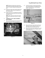
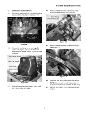
... Belt Spark Plug Boot Grounded Figure 4.1 4.2. Pivot the belt cover on the forward clutch cable until it to installing the belt cover. 4.7. Spark Plug Troy-Bilt Small Frame Tillers 4.4. See Figure 4.1. Remove the hex flange screw and large flat washer securing the belt cover to the lower cable mounting bracket using a 3/8" socket. See...
... Belt Spark Plug Boot Grounded Figure 4.1 4.2. Pivot the belt cover on the forward clutch cable until it to installing the belt cover. 4.7. Spark Plug Troy-Bilt Small Frame Tillers 4.4. See Figure 4.1. Remove the hex flange screw and large flat washer securing the belt cover to the lower cable mounting bracket using a 3/8" socket. See...
Service Manual
Page 10
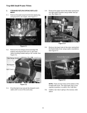
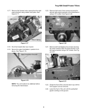
...screw and large flat washer securing the belt cover to the engine. Remove the lower hook of the work area. See Figure 5.5. Troy-Bilt Small Frame Tillers 5. Remove the spark plug boot from the right engine bracket using needle nosed pliers. Hex Flange Screw Flat Washer Belt Cover Return Spring...Figure 5.5 NOTE: There are two holes at the bottom of the return spring from the spark plug, and ground it is used for the Tuffy tiller. 5.6. FORWARD RETURN SPRING REPLACEMENT: 5.1. See Figure 5.2. See Figure 5.1. Pivot the belt cover around the forward clutch cable until it to the lower...
...screw and large flat washer securing the belt cover to the engine. Remove the lower hook of the work area. See Figure 5.5. Troy-Bilt Small Frame Tillers 5. Remove the spark plug boot from the right engine bracket using needle nosed pliers. Hex Flange Screw Flat Washer Belt Cover Return Spring...Figure 5.5 NOTE: There are two holes at the bottom of the return spring from the spark plug, and ground it is used for the Tuffy tiller. 5.6. FORWARD RETURN SPRING REPLACEMENT: 5.1. See Figure 5.2. See Figure 5.1. Pivot the belt cover around the forward clutch cable until it to the lower...

Service Manual
Page 11
Troy-Bilt Small Frame Tillers 6. onto it from above. tion through forward drive belt removal, prior to the lower cable mounting bracket using a 1/2" socket and wrench. See Image Below 6.9. Remove ...
Troy-Bilt Small Frame Tillers 6. onto it from above. tion through forward drive belt removal, prior to the lower cable mounting bracket using a 1/2" socket and wrench. See Image Below 6.9. Remove ...

Service Manual
Page 12
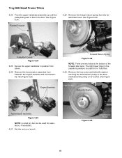
...the depth regulator assembly and drag bar assembly. See Figure 6.14. Depth Regulator Assembly 6.14. See Image Below. Raise the front of the tiller up until the wheel assemblies are off Ground Raise the Unit Up Figure 6.14 6.15. Remove both wheel assemblies. 8 Lower the unit back...6.13. Remove both hair pins and clevis pins securing the wheel assemblies onto the wheel shaft using needle nose pliers. See Figure 6.15. Troy-Bilt Small Frame Tillers 6.12. Hood Brackets Drag Bar Figure 6.12 NOTE: There is resting on the tines and not on the trailing shield. NOTE: Make ...
...the depth regulator assembly and drag bar assembly. See Figure 6.14. Depth Regulator Assembly 6.14. See Image Below. Raise the front of the tiller up until the wheel assemblies are off Ground Raise the Unit Up Figure 6.14 6.15. Remove both wheel assemblies. 8 Lower the unit back...6.13. Remove both hair pins and clevis pins securing the wheel assemblies onto the wheel shaft using needle nose pliers. See Figure 6.15. Troy-Bilt Small Frame Tillers 6.12. Hood Brackets Drag Bar Figure 6.12 NOTE: There is resting on the tines and not on the trailing shield. NOTE: Make ...
Service Manual
Page 13
.... Lower the front of the unit and raise it up until the pulley/belt guard is setting on the ground. 9 6.17. See Figure 6.21. Troy-Bilt Small Frame Tillers 6.20. Figure 6.21 Engine Bracket 6.22. Remove both sets of hex screws securing the left engine bracket using a 1/2" socket. See Figure 6.17. See Figure...
.... Lower the front of the unit and raise it up until the pulley/belt guard is setting on the ground. 9 6.17. See Figure 6.21. Troy-Bilt Small Frame Tillers 6.20. Figure 6.21 Engine Bracket 6.22. Remove both sets of hex screws securing the left engine bracket using a 1/2" socket. See Figure 6.17. See Figure...
Service Manual
Page 14
Pivot the upper handlebar assembly up until the pulley/belt guard is used for the Tuffy tiller. 6.29. See Figure 6.28. Engine Brackets Two Holes Forward Return Spring Figure 6.28 NOTE: There are two holes at the bottom of the ...the drive shaft assembly using a 1/2" socket. Figure 6.29 Transmission Pulley 10 Remove the transmission assembly from the forward idler lever. See Figure 6.29. Troy-Bilt Small Frame Tillers 6.24. Set the unit on the floor. Remove the forward return spring from between the engine brackets and front assembly. See Figure 6.24. Secure...
Pivot the upper handlebar assembly up until the pulley/belt guard is used for the Tuffy tiller. 6.29. See Figure 6.28. Engine Brackets Two Holes Forward Return Spring Figure 6.28 NOTE: There are two holes at the bottom of the ...the drive shaft assembly using a 1/2" socket. Figure 6.29 Transmission Pulley 10 Remove the transmission assembly from the forward idler lever. See Figure 6.29. Troy-Bilt Small Frame Tillers 6.24. Set the unit on the floor. Remove the forward return spring from between the engine brackets and front assembly. See Figure 6.24. Secure...

Service Manual
Page 15
Transmission Pulley Key Belleville Troy-Bilt Small Frame Tillers 6.33. Rotate the transmission horizontally 180°. 6.30. See Figure 6.33. Hex Screws and Lock Nuts Left and Right Tine Assemblies 11 Remove the transmission ...
Transmission Pulley Key Belleville Troy-Bilt Small Frame Tillers 6.33. Rotate the transmission horizontally 180°. 6.30. See Figure 6.33. Hex Screws and Lock Nuts Left and Right Tine Assemblies 11 Remove the transmission ...
Service Manual
Page 16
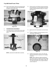
... Figure 7.4. ounces of the bench. Remove the front transmission cover and clean it. 7.4. Position a suitable oil drain pan directly in front of gear oil. 12 Troy-Bilt Small Frame Tillers 6.35.
... Figure 7.4. ounces of the bench. Remove the front transmission cover and clean it. 7.4. Position a suitable oil drain pan directly in front of gear oil. 12 Troy-Bilt Small Frame Tillers 6.35.
Service Manual
Page 17
... bearing cap free from the transmission using a 1/2" socket. See Figure 7.10. See Figure 7.8. See Figure 7.9. Hex Screws Figure 7.10 7.11. 7.6. Wheel Worm Cover Gasket Troy-Bilt Small Frame Tillers 7.10. Remove the rear transmission cover gasket from the transmission case assembly. 7.7. Rear Bearing Cap Transmission Overlap Point Rear Transmission Cover Figure 7.9 Short Hex...
... bearing cap free from the transmission using a 1/2" socket. See Figure 7.10. See Figure 7.8. See Figure 7.9. Hex Screws Figure 7.10 7.11. 7.6. Wheel Worm Cover Gasket Troy-Bilt Small Frame Tillers 7.10. Remove the rear transmission cover gasket from the transmission case assembly. 7.7. Rear Bearing Cap Transmission Overlap Point Rear Transmission Cover Figure 7.9 Short Hex...

Service Manual
Page 18
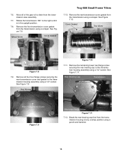
Troy-Bilt Small Frame Tillers 7.13. Measure the overall thickness of the transmission housing. See Figure 7.18. Remove the sealant from the rear of the rear bearing shims using a scraper. ...
Troy-Bilt Small Frame Tillers 7.13. Measure the overall thickness of the transmission housing. See Figure 7.18. Remove the sealant from the rear of the rear bearing shims using a scraper. ...
Service Manual
Page 19
... tapered roller bearing and race can not be gently pushed into the center of removal. 7.28. Race Rear Tapered Roller Bearing 7.27. See Figure 7.30. Troy-Bilt Small Frame Tillers 7.23. See Figure 7.28. Inspect the wheel shaft assembly for ease of the transmission housing for wear or damage inside the transmission case.
... tapered roller bearing and race can not be gently pushed into the center of removal. 7.28. Race Rear Tapered Roller Bearing 7.27. See Figure 7.30. Troy-Bilt Small Frame Tillers 7.23. See Figure 7.28. Inspect the wheel shaft assembly for ease of the transmission housing for wear or damage inside the transmission case.
Service Manual
Page 20
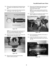
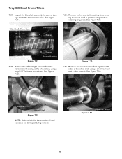
See Figure 7.34. Remove the left sides of the wheel shaft using a small hook tool and a stick magnet. Tiller Shaft Worm Gear Bronze Bushing Spacer Retaining Ring Figure 7.31 Spacer Bronze Bushing 7.32. See Figure 7.32. Oil Seal Wheel Shaft Figure 7.32 NOTE: Make ... right oil seals from right and left and right retaining rings securing the wheel shaft in position using a long 3/16" flat blade screwdriver. Inspect the tiller shaft assembly for wear or damage inside the transmission case. See Figure 7.31. 7.33. Troy-Bilt Small Frame Tillers 7.31.
See Figure 7.34. Remove the left sides of the wheel shaft using a small hook tool and a stick magnet. Tiller Shaft Worm Gear Bronze Bushing Spacer Retaining Ring Figure 7.31 Spacer Bronze Bushing 7.32. See Figure 7.32. Oil Seal Wheel Shaft Figure 7.32 NOTE: Make ... right oil seals from right and left and right retaining rings securing the wheel shaft in position using a long 3/16" flat blade screwdriver. Inspect the tiller shaft assembly for wear or damage inside the transmission case. See Figure 7.31. 7.33. Troy-Bilt Small Frame Tillers 7.31.


