
User Manual
Page 3
... cannot step on card or module. 9. Liquid can cause damage or electrical shock. 11. Discard used batteries with regular trash. DO NOT LEAVE THIS EQUIPMENT IN AN ENVIRONMENT UNCONDITIONED, STORAGE TEMPERATURE ABOVE 60 C (140F), IT MAY DAMAGE THE EQUIPMENT. Always read the safety instructions carefully. 2. Never pour any add-on it work according to User's Manual. • The equipment...
... cannot step on card or module. 9. Liquid can cause damage or electrical shock. 11. Discard used batteries with regular trash. DO NOT LEAVE THIS EQUIPMENT IN AN ENVIRONMENT UNCONDITIONED, STORAGE TEMPERATURE ABOVE 60 C (140F), IT MAY DAMAGE THE EQUIPMENT. Always read the safety instructions carefully. 2. Never pour any add-on it work according to User's Manual. • The equipment...
User Manual
Page 6
...ii Chapter 1 1 Specifications 1 Mainboard Specifications 2 Mainboard Layout 4 Back Panel Layout 5 Back Panel Ports 6 Slots 6 Onboard Connectors 7 Onboard Jumpers 7 Chapter 2 9 Installation 9 CPU 10 Memory Module Installation 12 Connecting the Power Supply 13 Back Panel Ports 14 Connectors 16 Jumpers 23 Slots 25 Chapter 3 27 BIOS Setup 27 Entering Setup 28 Control Keys 29 Navigating the BIOS Menus 30 Getting Help 31 Main Menu 32 Standard CMOS Features 34 IDE Drives 35 Advanced BIOS Features 36 CPU Feature 40 Hard Disk Boot Priority 42 Advanced Chipset Features 43...
...ii Chapter 1 1 Specifications 1 Mainboard Specifications 2 Mainboard Layout 4 Back Panel Layout 5 Back Panel Ports 6 Slots 6 Onboard Connectors 7 Onboard Jumpers 7 Chapter 2 9 Installation 9 CPU 10 Memory Module Installation 12 Connecting the Power Supply 13 Back Panel Ports 14 Connectors 16 Jumpers 23 Slots 25 Chapter 3 27 BIOS Setup 27 Entering Setup 28 Control Keys 29 Navigating the BIOS Menus 30 Getting Help 31 Main Menu 32 Standard CMOS Features 34 IDE Drives 35 Advanced BIOS Features 36 CPU Feature 40 Hard Disk Boot Priority 42 Advanced Chipset Features 43...

User Manual
Page 7
CPU & PCI Bus Control 47 TV Output Connector 48 Integrated Peripherals 49 VIA OnChip PCI Device 50 USB Device Setting 51 Power Management Setup 53 Wakeup Event Detect 55 PNP/PCI Configurations 57 Frequency / Voltage Control 59 DRAM Clock/Drive Control 60 Load Fail-Safe Defaults 62 Load Optimized Defaults 63 Set Supervisor / User Password 64 Save & Exit Setup 66 Exit Without Saving 67 Chapter 4 69 Driver Installation 69 Driver Utilities 70 CD Content 72 iii
CPU & PCI Bus Control 47 TV Output Connector 48 Integrated Peripherals 49 VIA OnChip PCI Device 50 USB Device Setting 51 Power Management Setup 53 Wakeup Event Detect 55 PNP/PCI Configurations 57 Frequency / Voltage Control 59 DRAM Clock/Drive Control 60 Load Fail-Safe Defaults 62 Load Optimized Defaults 63 Set Supervisor / User Password 64 Save & Exit Setup 66 Exit Without Saving 67 Chapter 4 69 Driver Installation 69 Driver Utilities 70 CD Content 72 iii
User Manual
Page 10
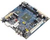
Chapter 1 MAINBOARD SPECIFICATIONS CPU • Support VIA C7 1.5GHz / 1.0GHz NanoBGA2 Processor Chipset • VIA CX700M Advanced All-in-one System Processor Graphics • Integrated UniChrome™ Pro II 3D/2D AGP with MPEG-2 and WMV9 Video Decoding Acceleration Audio • VIA VT1708A High Definition Audio Codec Memory • 1 x DDR2 533 DIMM slot (up to 1 GB) Expansion Slot • 1 x PCI slot IDE • 1 x UltraDMA 133/100/66/33 connector LAN • VIA VT6107 10/100 Mbps...
Chapter 1 MAINBOARD SPECIFICATIONS CPU • Support VIA C7 1.5GHz / 1.0GHz NanoBGA2 Processor Chipset • VIA CX700M Advanced All-in-one System Processor Graphics • Integrated UniChrome™ Pro II 3D/2D AGP with MPEG-2 and WMV9 Video Decoding Acceleration Audio • VIA VT1708A High Definition Audio Codec Memory • 1 x DDR2 533 DIMM slot (up to 1 GB) Expansion Slot • 1 x PCI slot IDE • 1 x UltraDMA 133/100/66/33 connector LAN • VIA VT6107 10/100 Mbps...
User Manual
Page 15
... VIP SCART and D-terminal Description Power cable connector CPU fan connector System fan connector +12V power connector IDE drive connector Front panel connector Front Audio connector Keyboard and Mouse connector LPC connector LVDS connector Serial ATA 1 and 2 connectors SMBus connector Universal Serial Bus 2.0 connectors 1/2-3/4 Audio Line-in connector IEEE 1394 connector VIP connector SCART and D-terminal connector(optional) ONBOARD JUMPERS Jumper CLEAR_CMOS IVDD_SEL PVDD_SEL Description Reset CMOS settings Set panel's input voltage Set signal voltage Specifications Page 12 10 10 10 15...
... VIP SCART and D-terminal Description Power cable connector CPU fan connector System fan connector +12V power connector IDE drive connector Front panel connector Front Audio connector Keyboard and Mouse connector LPC connector LVDS connector Serial ATA 1 and 2 connectors SMBus connector Universal Serial Bus 2.0 connectors 1/2-3/4 Audio Line-in connector IEEE 1394 connector VIP connector SCART and D-terminal connector(optional) ONBOARD JUMPERS Jumper CLEAR_CMOS IVDD_SEL PVDD_SEL Description Reset CMOS settings Set panel's input voltage Set signal voltage Specifications Page 12 10 10 10 15...
User Manual
Page 31
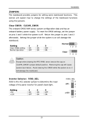
... when clearing the RTC RAM, never remove the cap on ; Removing the cap will damage the mainboard. Avoid clearing the CMOS while the system is on pins 2 and 3 while the system is the VCC selector jumper to determine the input voltage of the mainboard functions using the jumpers. Return the jumper to change the settings of the panel inverter for setting some mainboard functions. Installation JUMPERS The mainboard provides jumpers for panel's back-light. Setting the jumper...
... when clearing the RTC RAM, never remove the cap on ; Removing the cap will damage the mainboard. Avoid clearing the CMOS while the system is on pins 2 and 3 while the system is the VCC selector jumper to determine the input voltage of the mainboard functions using the jumpers. Return the jumper to change the settings of the panel inverter for setting some mainboard functions. Installation JUMPERS The mainboard provides jumpers for panel's back-light. Setting the jumper...

User Manual
Page 33
... or removing expansion card, unplug first the power supply. PCI PCI Interrupt Request Routing The IRQ (interrupt request line) are hardware lines over which devices can send interrupt signals to the system are typically connected to insert PCI expansion card. Read the documentation for the expansion card if any changes to the microprocessor. The "PCI & LAN" IRQ pins are necessary. SLOTS Installation Peripheral Component Interconnect: PCI1 The PCI slot...
... or removing expansion card, unplug first the power supply. PCI PCI Interrupt Request Routing The IRQ (interrupt request line) are hardware lines over which devices can send interrupt signals to the system are typically connected to insert PCI expansion card. Read the documentation for the expansion card if any changes to the microprocessor. The "PCI & LAN" IRQ pins are necessary. SLOTS Installation Peripheral Component Interconnect: PCI1 The PCI slot...

User Manual
Page 43
... 0 : Move Enter: Select F5: Previous Values +/-/PU/PD: Value F10: Save F6: Fail-Safe Defaults ESC: Exit F1: General Help F7: Optimized Defaults The specifications of your hard disk vendor or system manufacturer. Below is from your drive must match with the drive table. AwardBIOS CMOS Setup Utility IDE Channel 0 Master [Press Enter] Item Help IDE Channel 0 Master Access Mode Capacity [Auto] [Auto] 0 MB Menu Level To auto-detect the HDD's size, head... Select "Auto" whenever...
... 0 : Move Enter: Select F5: Previous Values +/-/PU/PD: Value F10: Save F6: Fail-Safe Defaults ESC: Exit F1: General Help F7: Optimized Defaults The specifications of your hard disk vendor or system manufacturer. Below is from your drive must match with the drive table. AwardBIOS CMOS Setup Utility IDE Channel 0 Master [Press Enter] Item Help IDE Channel 0 Master Access Mode Capacity [Auto] [Auto] 0 MB Menu Level To auto-detect the HDD's size, head... Select "Auto" whenever...
User Manual
Page 44
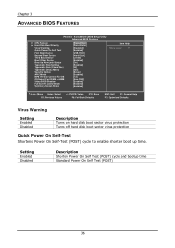
... CMOS Setup Utility Advanced BIOS Features CPU Feature Hard Disk Boot Priority Virus Warning Quick Power On Self Test First Boot Device Second Boot Device Third Boot Device Boot Other Device Boot Up NumLock Status Typematic Rate Setting Typematic Rate (Chars/Sec) Typematic Delay (Msec) Security Option APIC Mode MPS Version Control For OS OS Select For DRAM > 64MB Video BIOS Shadow Full Screen LOGO Show Summary Screen Show [Press Enter] [Press Enter] [Disabled] [Enabled] [USB-FDD] [Hard Disk] [LS120] [Enabled] [On] [Enabled] [30] [250] [Setup] [Enabled] [1.4] [Non-OS2] [Enabled] [Enabled...
... CMOS Setup Utility Advanced BIOS Features CPU Feature Hard Disk Boot Priority Virus Warning Quick Power On Self Test First Boot Device Second Boot Device Third Boot Device Boot Other Device Boot Up NumLock Status Typematic Rate Setting Typematic Rate (Chars/Sec) Typematic Delay (Msec) Security Option APIC Mode MPS Version Control For OS OS Select For DRAM > 64MB Video BIOS Shadow Full Screen LOGO Show Summary Screen Show [Press Enter] [Press Enter] [Disabled] [Enabled] [USB-FDD] [Hard Disk] [LS120] [Enabled] [On] [Enabled] [30] [250] [Setup] [Enabled] [1.4] [Non-OS2] [Enabled] [Enabled...
User Manual
Page 45
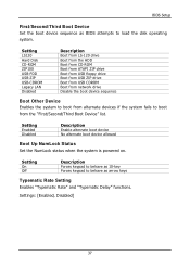
..., Disabled] 37 Setting LS120 Hard Disk CD-ROM ZIP100 USB-FDD USB-ZIP USB-CDROM Legacy LAN Disabled Description Boot from LS-120 drive Boot from the HDD Boot from CD-ROM Boot from ATAPI ZIP drive Boot from USB floppy drive Boot from USB ZIP drive Boot from USB CDROM Boot from network drive Disable the boot device sequence Boot Other Device Enables the system to boot from the "First/Second/Third Boot Device" list. Setting Enabled Disabled Description Enable alternate boot device No alternate boot device allowed Boot Up NumLock Status Set the NumLock status when the system is powered...
..., Disabled] 37 Setting LS120 Hard Disk CD-ROM ZIP100 USB-FDD USB-ZIP USB-CDROM Legacy LAN Disabled Description Boot from LS-120 drive Boot from the HDD Boot from CD-ROM Boot from ATAPI ZIP drive Boot from USB floppy drive Boot from USB ZIP drive Boot from USB CDROM Boot from network drive Disable the boot device sequence Boot Other Device Enables the system to boot from the "First/Second/Third Boot Device" list. Setting Enabled Disabled Description Enable alternate boot device No alternate boot device allowed Boot Up NumLock Status Set the NumLock status when the system is powered...

User Manual
Page 46
Settings: [Enabled, Disabled] MPS Variation Control for OS Settings: [1.1, 1.4] OS Select For DRAM > 64MB Select OS2 only if you enter Setup. Settings: [Enabled, Disabled] 38 Settings: [Non-OS2, OS2] Video BIOS Shadow Enabled copies Video BIOS to repeat the signal from a depressed key. Setting Setup System Description Password prompt appears only when end users try to run BIOS Setup Password prompt appears every time when the computer is required every time the System boots, or only when...
Settings: [Enabled, Disabled] MPS Variation Control for OS Settings: [1.1, 1.4] OS Select For DRAM > 64MB Select OS2 only if you enter Setup. Settings: [Enabled, Disabled] 38 Settings: [Non-OS2, OS2] Video BIOS Shadow Enabled copies Video BIOS to repeat the signal from a depressed key. Setting Setup System Description Password prompt appears only when end users try to run BIOS Setup Password prompt appears every time when the computer is required every time the System boots, or only when...

User Manual
Page 53
AwardBIOS CMOS Setup Utility AGP & P2P Bridge Control AGP Aperture Size AGP 2.0 Mode AGP Driving Control x AGP Driving Value AGP Fast Write AGP Master 1 WS Write AGP Master 1 WS Read AGP 3.0 Calibration cycle VGA Share Memory Size Direct Frame Buffer [128M] [4x] [Auto] DA [Disabled] [Enabled] [Enabled] [Enabled] [64M] [Enabled] Item Help Menu Level : Move Enter: Select F5: Previous Values +/-/PU/PD: Value F10: Save F6: Fail-Safe Defaults ESC: Exit F1: General...
AwardBIOS CMOS Setup Utility AGP & P2P Bridge Control AGP Aperture Size AGP 2.0 Mode AGP Driving Control x AGP Driving Value AGP Fast Write AGP Master 1 WS Write AGP Master 1 WS Read AGP 3.0 Calibration cycle VGA Share Memory Size Direct Frame Buffer [128M] [4x] [Auto] DA [Disabled] [Enabled] [Enabled] [Enabled] [64M] [Enabled] Item Help Menu Level : Move Enter: Select F5: Previous Values +/-/PU/PD: Value F10: Save F6: Fail-Safe Defaults ESC: Exit F1: General...

User Manual
Page 54
Settings: [Auto, Manual] AGP Fast Write This item is used to auto or manual. Chapter 3 AGP Driving Control This item is used to signal driving current on AGP cards to enable or disable the caching of display data for the video memory of the processor. Settings: [Enabled, Disabled] AGP Master 1 WS Write Settings: [Enabled, Disabled] AGP Master 1 WS Read Settings: [Enabled, Disabled] AGP 3.0 Calibration Cycle Settings: [Enabled, Disabled] VGA Share Memory Size Settings: [Disabled, 32M, 64M, 128M] Direct Frame Buffer Settings: [Enabled, Disabled] 46
Settings: [Auto, Manual] AGP Fast Write This item is used to auto or manual. Chapter 3 AGP Driving Control This item is used to signal driving current on AGP cards to enable or disable the caching of display data for the video memory of the processor. Settings: [Enabled, Disabled] AGP Master 1 WS Write Settings: [Enabled, Disabled] AGP Master 1 WS Read Settings: [Enabled, Disabled] AGP 3.0 Calibration Cycle Settings: [Enabled, Disabled] VGA Share Memory Size Settings: [Disabled, 32M, 64M, 128M] Direct Frame Buffer Settings: [Enabled, Disabled] 46

User Manual
Page 58
Chapter 3 VIA ONCHIP PCI DEVICE Azalia HDA Controller OnBoard LAN Boot ROM Phoenix - AwardBIOS CMOS Setup Utility VIA OnChip PCI Device [Auto] [Disabled] Item Help Menu Level : Move Enter: Select F5: Previous Values +/-/PU/PD: Value F10: Save F6: Fail-Safe Defaults ESC: Exit F1: General Help F7: Optimized Defaults Azalia HDA Controller Settings: [Auto, Disabled] OnBoard LAN Boot ROM Settings: [Enabled, Disabled] 50
Chapter 3 VIA ONCHIP PCI DEVICE Azalia HDA Controller OnBoard LAN Boot ROM Phoenix - AwardBIOS CMOS Setup Utility VIA OnChip PCI Device [Auto] [Disabled] Item Help Menu Level : Move Enter: Select F5: Previous Values +/-/PU/PD: Value F10: Save F6: Fail-Safe Defaults ESC: Exit F1: General Help F7: Optimized Defaults Azalia HDA Controller Settings: [Auto, Disabled] OnBoard LAN Boot ROM Settings: [Enabled, Disabled] 50

User Manual
Page 59
...BIOS Setup USB 1.0 Controller USB 2.0 Controller USB Operation Mode USB Keyboard Function USB Storage Function Phoenix - AwardBIOS CMOS Setup Utility USB Device Setting [Enabled] [Enabled] [High Speed] [Enabled] [Enabled] *** USB Mass Storage Device Boot Setting *** UFDDA USB Floppy UFDDB USB Floppy No Device [Auto mode] No Device [Auto mode] No Device [Auto mode] No Device [Auto mode] No Device [Auto mode] No Device [Auto mode] No Device [Auto mode] No Device [Auto mode] Item Help Menu Level [Enable] or [Disable] Universal Host Controller Interface for Universal Serial...
...BIOS Setup USB 1.0 Controller USB 2.0 Controller USB Operation Mode USB Keyboard Function USB Storage Function Phoenix - AwardBIOS CMOS Setup Utility USB Device Setting [Enabled] [Enabled] [High Speed] [Enabled] [Enabled] *** USB Mass Storage Device Boot Setting *** UFDDA USB Floppy UFDDB USB Floppy No Device [Auto mode] No Device [Auto mode] No Device [Auto mode] No Device [Auto mode] No Device [Auto mode] No Device [Auto mode] No Device [Auto mode] No Device [Auto mode] Item Help Menu Level [Enable] or [Disable] Universal Host Controller Interface for Universal Serial...

User Manual
Page 65
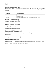
... [Auto(ESCD)] Press Enter PCI/VGA Palette Snoop Assign IRQ For VGA Assign IRQ For USB [Disabled] [Enabled] [Enabled] ** PCI Express relative items ** Maximum ASPM supported Maximum Payload Size [L0s&L1] [4096] Item Help Menu Level Select Yes if you are using a Plug and Play capable operating system. Setting Enabled Disabled Description Resets the ESCD (Extended System Configuration Data) after exiting BIOS Setup if a newly installed PCI card or the system configuration prevents the operating system from loading Default setting...
... [Auto(ESCD)] Press Enter PCI/VGA Palette Snoop Assign IRQ For VGA Assign IRQ For USB [Disabled] [Enabled] [Enabled] ** PCI Express relative items ** Maximum ASPM supported Maximum Payload Size [L0s&L1] [4096] Item Help Menu Level Select Yes if you are using a Plug and Play capable operating system. Setting Enabled Disabled Description Resets the ESCD (Extended System Configuration Data) after exiting BIOS Setup if a newly installed PCI card or the system configuration prevents the operating system from loading Default setting...
User Manual
Page 66
..., L0s&L1] Maximum Payload Size Set maximum TLP payload size for VGA and USB devices. Setting Auto(ESCD) Manual Description BIOS will automatically assign IRQ, DMA and memory base address fields Unlocks "IRQ Resources" for manual configuration PCI/VGA Palette Snoop Settings: [Disabled, Enabled] Assign IRQ For VGA/USB Assign IRQ for the PCI Express devices. Settings: [128, 256, 512, 1024, 2048, 4096] 58 Chapter 3 Resource Controlled By Enables the BIOS to automatically configure all the Plug-and-Play compatible devices.
..., L0s&L1] Maximum Payload Size Set maximum TLP payload size for VGA and USB devices. Setting Auto(ESCD) Manual Description BIOS will automatically assign IRQ, DMA and memory base address fields Unlocks "IRQ Resources" for manual configuration PCI/VGA Palette Snoop Settings: [Disabled, Enabled] Assign IRQ For VGA/USB Assign IRQ for the PCI Express devices. Settings: [128, 256, 512, 1024, 2048, 4096] 58 Chapter 3 Resource Controlled By Enables the BIOS to automatically configure all the Plug-and-Play compatible devices.

User Manual
Page 68
...] [1T/2T] [4T] [Auto] 03 Item Help Menu Level : Move Enter: Select F5: Previous Values +/-/PU/PD: Value F10: Save F6: Fail-Safe Defaults ESC: Exit F1: General Help F7: Optimized Defaults DRAM Clock The chipset supports synchronous and asynchronous mode between host clock and DRAM clock frequency. Settings: [Manual, Auto By SPD] 60 Changing the value from the factory setting is not recommended unless you install new memory that has a different...
...] [1T/2T] [4T] [Auto] 03 Item Help Menu Level : Move Enter: Select F5: Previous Values +/-/PU/PD: Value F10: Save F6: Fail-Safe Defaults ESC: Exit F1: General Help F7: Optimized Defaults DRAM Clock The chipset supports synchronous and asynchronous mode between host clock and DRAM clock frequency. Settings: [Manual, Auto By SPD] 60 Changing the value from the factory setting is not recommended unless you install new memory that has a different...

User Manual
Page 79
Driver Installation Running the Driver Utilities CD To start using the CD, insert the CD into the CD-ROM or DVD-ROM drive. The CD should then appear on the "Start" button and select "Run..." Then type: "D:\Setup.exe". If the CD does not run automatically after closing the CD-ROM or DVD-ROM drive. The driver utilities and software menu screen should run automatically, click on the screen. Note: D: might not be the drive letter of the CD-ROM/DVD-ROM in your system. 71
Driver Installation Running the Driver Utilities CD To start using the CD, insert the CD into the CD-ROM or DVD-ROM drive. The CD should then appear on the "Start" button and select "Run..." Then type: "D:\Setup.exe". If the CD does not run automatically after closing the CD-ROM or DVD-ROM drive. The driver utilities and software menu screen should run automatically, click on the screen. Note: D: might not be the drive letter of the CD-ROM/DVD-ROM in your system. 71

User Manual
Page 80
... Hard Disk Drives and ensures IDE device compatibility), AGP VxD Driver (provides service routines to your VGA driver and interface directly to hardware, providing fast graphical access), IRQ Routing Miniport Driver (sets the system's PCI IRQ routing sequence) and VIA INF Driver (enables the VIA Power Management function). VIA Graphics Driver: Enhances the onboard VIA graphic chip. VIA GigaLAN Driver: Enhances the onboard optional VIA VT6122 10/100/1000M LAN chip. VIA Audio Driver: Enhances the onboard VIA audio chip. VIA USB 2.0 Driver: Enhances VIA USB 2.0 ports. VIA LAN Driver: Enhances...
... Hard Disk Drives and ensures IDE device compatibility), AGP VxD Driver (provides service routines to your VGA driver and interface directly to hardware, providing fast graphical access), IRQ Routing Miniport Driver (sets the system's PCI IRQ routing sequence) and VIA INF Driver (enables the VIA Power Management function). VIA Graphics Driver: Enhances the onboard VIA graphic chip. VIA GigaLAN Driver: Enhances the onboard optional VIA VT6122 10/100/1000M LAN chip. VIA Audio Driver: Enhances the onboard VIA audio chip. VIA USB 2.0 Driver: Enhances VIA USB 2.0 ports. VIA LAN Driver: Enhances...
