

English Manual
Page 2
... REPLACEMENT PARTS Back Cover LIMITED WARRANTY Back Cover Note: A PART LIST/EXPLODED DRAWING is attached in the center of ICON Health & Fitness, Inc. 2 If a decal is a registered trademark of this product may result in the location shown. ! WEIDER is missing or illegible, please call our Customer Service Department toll-free at 1800...
... REPLACEMENT PARTS Back Cover LIMITED WARRANTY Back Cover Note: A PART LIST/EXPLODED DRAWING is attached in the center of ICON Health & Fitness, Inc. 2 If a decal is a registered trademark of this product may result in the location shown. ! WEIDER is missing or illegible, please call our Customer Service Department toll-free at 1800...

English Manual
Page 4
...be found on the drawings in muscle size and strength, or a healthier cardiovascular system, the WEIDER® PRO XT75 will help you achieve the specific results you have additional questions, please .... For your goal is a shapely figure, dramatic increase in the manual. until 6 p.m. The WEIDER® PRO XT75 is WEBE34111A. Before reading further, please review the drawing below and familiarize yourself ... rackp (see the front cover of the body. To help you for selecting the versatile WEIDER® PRO XT75 weight rack. High Pulley Station Chin-up Bar Right Side Lat Bar...
...be found on the drawings in muscle size and strength, or a healthier cardiovascular system, the WEIDER® PRO XT75 will help you achieve the specific results you have additional questions, please .... For your goal is a shapely figure, dramatic increase in the manual. until 6 p.m. The WEIDER® PRO XT75 is WEBE34111A. Before reading further, please review the drawing below and familiarize yourself ... rackp (see the front cover of the body. To help you for selecting the versatile WEIDER® PRO XT75 weight rack. High Pulley Station Chin-up Bar Right Side Lat Bar...
English Manual
Page 5
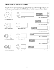
... (33) 5 If a part is the key number of this manual. PART IDENTIFICATION CHART Refer to the drawings below to see if it has been pre-attached. The number in parentheses by each drawing is not in the parts bag, check to identify small parts used in the center of the part...
... (33) 5 If a part is the key number of this manual. PART IDENTIFICATION CHART Refer to the drawings below to see if it has been pre-attached. The number in parentheses by each drawing is not in the parts bag, check to identify small parts used in the center of the part...

English Manual
Page 6
... and that the weight rack can be pre-assembled. Press a 60mm Square Outer Cap (28) onto the end of the Weight Guide Base (4). 2 Attach the Foot Plate (5) and the Weight Guide Base (4) to the Center Base (2), as shown in a cleared area and remove the packing materials. Do...PART IDENTIFICATION CHART on page 5. Important: Some of the packing materials until assembly is important to ensure that the assembly process will take time. Attach the Right and Left Bases (1, 3) to do otherwise. • As you understand the information in the assembly steps may be assembled successfully ...
... and that the weight rack can be pre-assembled. Press a 60mm Square Outer Cap (28) onto the end of the Weight Guide Base (4). 2 Attach the Foot Plate (5) and the Weight Guide Base (4) to the Center Base (2), as shown in a cleared area and remove the packing materials. Do...PART IDENTIFICATION CHART on page 5. Important: Some of the packing materials until assembly is important to ensure that the assembly process will take time. Attach the Right and Left Bases (1, 3) to do otherwise. • As you understand the information in the assembly steps may be assembled successfully ...

English Manual
Page 7
... Do not tighten the Nylon Locknuts yet. Make sure both Weight Spotters and both Weight Rests are slightly shorter than the Front Uprights (not shown). Attach the Rear Uprights to drawing 5a. If they do not line up . Refer to the Right and Left Bases (1, 3) using four M10 x 78mm... Bolts (33) and four M10 Nylon Locknuts (31). Tap a 60mm Square Inner Cap (29) into each other. 1 33 Attach the other Front Upright (7, not shown) and two Joint Plates (6, not shown) to the right Uprights (7, 8) by tightening each of the three Adjustment Knobs (22...
... Do not tighten the Nylon Locknuts yet. Make sure both Weight Spotters and both Weight Rests are slightly shorter than the Front Uprights (not shown). Attach the Rear Uprights to drawing 5a. If they do not line up . Refer to the Right and Left Bases (1, 3) using four M10 x 78mm... Bolts (33) and four M10 Nylon Locknuts (31). Tap a 60mm Square Inner Cap (29) into each other. 1 33 Attach the other Front Upright (7, not shown) and two Joint Plates (6, not shown) to the right Uprights (7, 8) by tightening each of the three Adjustment Knobs (22...

English Manual
Page 8
... Left Frame (12). Press a 60mm Square Inner Cap (29) into the Weight Carriage (15). Tighten all Nylon Locknuts (31) used in the Weight Guide Base (4). Attach the lower Carriage Bushing using two M8 x 72mm Bolts (35), four M8 Flat Washers (40), and two M8 Nylon Locknuts (32). 8 9 15 32 18 4... (7, 8) using four M10 x 78mm Bolts (33) and four M10 Nylon Locknuts (31). Set the two Weight Bumpers (18) over the indicated holes in steps 1-7. 8. Attach the Left Frame to the right Uprights (7, 8) in the same manner. Make sure the Weight Carriage is turned so the weight tubes are near the...
... Left Frame (12). Press a 60mm Square Inner Cap (29) into the Weight Carriage (15). Tighten all Nylon Locknuts (31) used in the Weight Guide Base (4). Attach the lower Carriage Bushing using two M8 x 72mm Bolts (35), four M8 Flat Washers (40), and two M8 Nylon Locknuts (32). 8 9 15 32 18 4... (7, 8) using four M10 x 78mm Bolts (33) and four M10 Nylon Locknuts (31). Set the two Weight Bumpers (18) over the indicated holes in steps 1-7. 8. Attach the Left Frame to the right Uprights (7, 8) in the same manner. Make sure the Weight Carriage is turned so the weight tubes are near the...
English Manual
Page 9
... of the Weight Carriage (15). Press a 60mm Square Inner Cap (29) into the hole in the location shown. Attach two Pulleys (25) inside the bracket on the Weight Guide Frame (14), down through the indicated hole, back up ...is the longer of the High Cable and a metal sleeve on one end of the two Cables. Attach the 12 High Cable using two M10 x 50mm Bolts (47) and two M10 Nylon Locknuts (31). 9 25 31... 26 14 47 Attach the Weight Guide Frame (14) to the Weight Guide Frame using two M10 x 78mm Bolts (33), two...
... of the Weight Carriage (15). Press a 60mm Square Inner Cap (29) into the hole in the location shown. Attach two Pulleys (25) inside the bracket on the Weight Guide Frame (14), down through the indicated hole, back up ...is the longer of the High Cable and a metal sleeve on one end of the two Cables. Attach the 12 High Cable using two M10 x 50mm Bolts (47) and two M10 Nylon Locknuts (31). 9 25 31... 26 14 47 Attach the Weight Guide Frame (14) to the Weight Guide Frame using two M10 x 78mm Bolts (33), two...

English Manual
Page 10
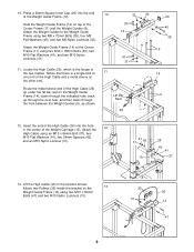
... in the location shown. 14. Lift the High Cable (26) in the Pulley Plates. Lay the Low Cable (27) over a Pulley (25) as shown. 16 Attach a Cable Trap (24) and the two Pulley Plates (17) to the Pulley Plates (17) using an M10 x 75mm Bolt (36), two M10 Flat Washers (41... sure the Bolts are between the Cable Traps and the Pulleys. 10 26 17 31 27 4 44 41 36 34 25 24 17 34 24 Attach two Pulleys (25) inside the bracket using two M10 x 75mm Bolts (36), four M10 Flat Washers (41), four 18mm Spacers (45), and two M10 Nylon...
... in the location shown. 14. Lift the High Cable (26) in the Pulley Plates. Lay the Low Cable (27) over a Pulley (25) as shown. 16 Attach a Cable Trap (24) and the two Pulley Plates (17) to the Pulley Plates (17) using an M10 x 75mm Bolt (36), two M10 Flat Washers (41... sure the Bolts are between the Cable Traps and the Pulleys. 10 26 17 31 27 4 44 41 36 34 25 24 17 34 24 Attach two Pulleys (25) inside the bracket using two M10 x 75mm Bolts (36), four M10 Flat Washers (41), four 18mm Spacers (45), and two M10 Nylon...

English Manual
Page 13
... station, slide the desired amount of weight onto the weight tubes of the Weight Carriage (15) and secure the weights with a Cable Clip (23). Next, attach the Lat Bar (38) to the High Cable (26) or the Low Cable (not shown) with Weight Clips (50). Weight Tube Weight Tube 15 50... the Pulley Plates using the Lat Bar. Reattach the lower Pulley and Cable Trap to the two Pulley Plates (17). If there is first used. ATTACHING WEIGHTS TO THE WEIGHT CARRIAGE To use the high pulley station or the low pulley station, first place the desired weights on the Weight Carriage...
... station, slide the desired amount of weight onto the weight tubes of the Weight Carriage (15) and secure the weights with a Cable Clip (23). Next, attach the Lat Bar (38) to the High Cable (26) or the Low Cable (not shown) with Weight Clips (50). Weight Tube Weight Tube 15 50... the Pulley Plates using the Lat Bar. Reattach the lower Pulley and Cable Trap to the two Pulley Plates (17). If there is first used. ATTACHING WEIGHTS TO THE WEIGHT CARRIAGE To use the high pulley station or the low pulley station, first place the desired weights on the Weight Carriage...

