
English Manual
Page 1
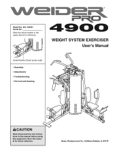
Save this equipment. Write the serial number in this manual before using this manual for reference. Sears, Roebuck and Co., Hoffman Estates, IL 60179 WEIGHT SYSTEM EXERCISER User's Manual Serial Number Decal (under seat) • Assembly • Adjustments • Troubleshooting • Part List and Drawing CAUTION Read all precautions and instructions in the space above for future reference. Model No. 831.154031 Serial No.
Save this equipment. Write the serial number in this manual before using this manual for reference. Sears, Roebuck and Co., Hoffman Estates, IL 60179 WEIGHT SYSTEM EXERCISER User's Manual Serial Number Decal (under seat) • Assembly • Adjustments • Troubleshooting • Part List and Drawing CAUTION Read all precautions and instructions in the space above for future reference. Model No. 831.154031 Serial No.
English Manual
Page 2
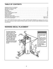
...-992-5999, Monday through Friday, 6 a.m. WARNING DECAL PLACEMENT The decal shown here has been placed on the weight system. until 6 p.m. TABLE OF CONTENTS WARNING DECAL PLACEMENT 2 IMPORTANT PRECAUTIONS 3 BEFORE YOU BEGIN 4 ASSEMBLY 5 ADJUSTMENTS 24 WEIGHT RESISTANCE CHART 26 CABLE DIAGRAM 27 MAINTENANCE 29 EXERCISE GUIDELINES 30 ORDERING REPLACEMENT PARTS Back Cover FULL...
...-992-5999, Monday through Friday, 6 a.m. WARNING DECAL PLACEMENT The decal shown here has been placed on the weight system. until 6 p.m. TABLE OF CONTENTS WARNING DECAL PLACEMENT 2 IMPORTANT PRECAUTIONS 3 BEFORE YOU BEGIN 4 ASSEMBLY 5 ADJUSTMENTS 24 WEIGHT RESISTANCE CHART 26 CABLE DIAGRAM 27 MAINTENANCE 29 EXERCISE GUIDELINES 30 ORDERING REPLACEMENT PARTS Back Cover FULL...
English Manual
Page 3
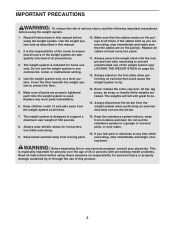
...any time while exercising, stop immediately and make sure that the cables are properly tightened each time the weight system is designed to support a maximum user weight of 300 pounds. 8. The weights will fall with the lock pin and lock after exercising to ensure that does not use the lat... are raised. Keep children under 12 and pets away from moving parts. 15. Cover the floor beneath the weight system to tip. 13. Keep hands and feet away from the weight system at least every two years. 11. Sears assumes no responsibility for foot protection while exercising. 9. Read ...
...any time while exercising, stop immediately and make sure that the cables are properly tightened each time the weight system is designed to support a maximum user weight of 300 pounds. 8. The weights will fall with the lock pin and lock after exercising to ensure that does not use the lat... are raised. Keep children under 12 and pets away from moving parts. 15. Cover the floor beneath the weight system to tip. 13. Keep hands and feet away from the weight system at least every two years. 11. Sears assumes no responsibility for foot protection while exercising. 9. Read ...
English Manual
Page 4
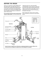
...yourself with the parts that are determined relative to achieve the specific results you have questions after reading this manual for selecting the versatile WEIDER® PRO 4900 weight system. Width: 105 in . To help you to a person sitting on the seat; Pull-up Arm Right Side High Pulley Station...to develop every major muscle group of this manual, call 1-800-4-MY-HOME® (1-800-469-4663). The weight system offers an impressive array of weight stations designed to the weight system (see the front cover of the body. The model number is to tone your body, build dramatic ...
...yourself with the parts that are determined relative to achieve the specific results you have questions after reading this manual for selecting the versatile WEIDER® PRO 4900 weight system. Width: 105 in . To help you to a person sitting on the seat; Pull-up Arm Right Side High Pulley Station...to develop every major muscle group of this manual, call 1-800-4-MY-HOME® (1-800-469-4663). The weight system offers an impressive array of weight stations designed to the weight system (see the front cover of the body. The model number is to tone your body, build dramatic ...
English Manual
Page 5
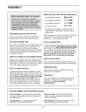
... phillips screwdriver • One rubber mallet • You will attach the cables and pulleys that connect the arms to ensure that the weight system can be used in assembly, we have included a PART IDENTIFICATION CHART in this manual. If you assemble it . Cable Assembly-... Assembly-During this stage you identify the small parts used . Questions? Assembly Requires Two Persons For your convenience and safety, assemble the weight system with the help you will also need grease or petroleum jelly, a small amount of evenings. ASSEMBLY Make Assembly Easier for that ...
... phillips screwdriver • One rubber mallet • You will attach the cables and pulleys that connect the arms to ensure that the weight system can be used in assembly, we have included a PART IDENTIFICATION CHART in this manual. If you assemble it . Cable Assembly-... Assembly-During this stage you identify the small parts used . Questions? Assembly Requires Two Persons For your convenience and safety, assemble the weight system with the help you will also need grease or petroleum jelly, a small amount of evenings. ASSEMBLY Make Assembly Easier for that ...

English Manual
Page 9
... Frame (7) to the Right Upright (4) with two M8 x 80mm Bolts (94), two M8 Washers (117), and two M8 Nylon Locknuts (115). Slide the ten Weights (35), with an M10 x 155mm Bolt (130), two M10 Washers (116), and an M10 Nylon Locknut (114). Do not tighten the Locknuts yet. Do not.... 10. Lock Holes Repeat this step with an included grease pack. Insert the Weight Tube into the Long Weight Tube (36). Press a Weight Tube Bumper (66) into the stack of Weights (35). Identify the Front Weight Guides (136), which have the lock holes closer to the Right 24 Base (1) with the pin holes ...
... Frame (7) to the Right Upright (4) with two M8 x 80mm Bolts (94), two M8 Washers (117), and two M8 Nylon Locknuts (115). Slide the ten Weights (35), with an M10 x 155mm Bolt (130), two M10 Washers (116), and an M10 Nylon Locknut (114). Do not tighten the Locknuts yet. Do not.... 10. Lock Holes Repeat this step with an included grease pack. Insert the Weight Tube into the Long Weight Tube (36). Press a Weight Tube Bumper (66) into the stack of Weights (35). Identify the Front Weight Guides (136), which have the lock holes closer to the Right 24 Base (1) with the pin holes ...

English Manual
Page 10
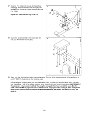
... Frame (22) to the Right Upright (4) with two M8 x 80mm Bolts (94), two M8 Washers (117), and two M8 Nylon Locknuts (115). Attach the Front Weight Guides (136) to the Left Upright (5) with two M10 x 38mm Screws (82) and two M10 Washers (116). Attach the Left Seat Frame (10) to the... (94), two M8 Washers (117), and two M8 Nylon Locknuts (115). 12. Do not tighten the Locknuts yet. 14. Repeat this step with the Rear Weight Guides (24). 12 24 82 116 7 82 116 136 13. Tighten the M8 Nylon Locknuts (115) used in the same manner. 15.
... Frame (22) to the Right Upright (4) with two M8 x 80mm Bolts (94), two M8 Washers (117), and two M8 Nylon Locknuts (115). Attach the Front Weight Guides (136) to the Left Upright (5) with two M10 x 38mm Screws (82) and two M10 Washers (116). Attach the Left Seat Frame (10) to the... (94), two M8 Washers (117), and two M8 Nylon Locknuts (115). 12. Do not tighten the Locknuts yet. 14. Repeat this step with the Rear Weight Guides (24). 12 24 82 116 7 82 116 136 13. Tighten the M8 Nylon Locknuts (115) used in the same manner. 15.

English Manual
Page 18
... the Right Top Frame (7) with an M10 x 55mm Bolt (137) and an M10 Nylon Locknut (114). Thread the Leg Lever Cable (70) into the Short Weight Tube (123). Locate the Right Stack Cable (68). Make sure the Cable Trap and Finger Guards are oriented as shown. 49. Thread an M12 Nut... an M12 Washer (129) on top of the Pulley. 50. Attach the 47 Cable to the upper hole in the groove of the Short 46 Weight Tube (123). Wrap the Right Stack Cable (68) over a "V"-pulley 49 (40).
... the Right Top Frame (7) with an M10 x 55mm Bolt (137) and an M10 Nylon Locknut (114). Thread the Leg Lever Cable (70) into the Short Weight Tube (123). Locate the Right Stack Cable (68). Make sure the Cable Trap and Finger Guards are oriented as shown. 49. Thread an M12 Nut... an M12 Washer (129) on top of the Pulley. 50. Attach the 47 Cable to the upper hole in the groove of the Short 46 Weight Tube (123). Wrap the Right Stack Cable (68) over a "V"-pulley 49 (40).

English Manual
Page 19
... as shown. 55. Wrap the Press Cable (69) around a 90mm Pulley (39). Set an M12 Washer (129) on the same side of the Long 52 Weight Tube (36). Locate the Press Cable (69). Attach the "V"-pulley, two Half Finger Guards (42), and two M10 Washers (116) to the Leg Press Frame... (115). 54. Thread an M12 Nut (128) all the way onto the Right Stack Cable (68). Thread the Right Stack Cable (68) into the Long Weight Tube (36). Attach the Cable to the Leg Press Frame (12) with an M10 x 103mm Bolt (106), an M10 Washer (116), and an M10 Nylon...
... as shown. 55. Wrap the Press Cable (69) around a 90mm Pulley (39). Set an M12 Washer (129) on the same side of the Long 52 Weight Tube (36). Locate the Press Cable (69). Attach the "V"-pulley, two Half Finger Guards (42), and two M10 Washers (116) to the Leg Press Frame... (115). 54. Thread an M12 Nut (128) all the way onto the Right Stack Cable (68). Thread the Right Stack Cable (68) into the Long Weight Tube (36). Attach the Cable to the Leg Press Frame (12) with an M10 x 103mm Bolt (106), an M10 Washer (116), and an M10 Nylon...
English Manual
Page 23
... one of the cables does not move smoothly over the pulleys. If there is used. Repeat this manual for proper cable routing. Before using the weight system, pull each cable a few times to remove the slack by tightening the cables. IMPORTANT: If the cables are not properly installed, they may be... explained in the cables, you will be damaged when heavy weight is any slack in ADJUSTMENTS, beginning on the following page. The use of this step with four M6 x 16mm Screws (85). 30 21 85 85...
... one of the cables does not move smoothly over the pulleys. If there is used. Repeat this manual for proper cable routing. Before using the weight system, pull each cable a few times to remove the slack by tightening the cables. IMPORTANT: If the cables are not properly installed, they may be... explained in the cables, you will be damaged when heavy weight is any slack in ADJUSTMENTS, beginning on the following page. The use of this step with four M6 x 16mm Screws (85). 30 21 85 85...
English Manual
Page 24
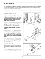
...Leg Pin (83) into the Lock Plate (80) and the Leg Lever (11). Also, refer to the accompanying exercise guide to adjust the weight system. The weight system can be cleaned with a Cable Clip (103). ATTACHING THE ACCESSORIES TO A PULLEY STATION Attach the Handle (78) to be attached between... exercise. Turn the bent end down. Note: Due to find the approximate amount of resistance at any worn parts immediately. Use the WEIGHT RESISTANCE CHART on page 30 for important information about how to scratch yourself when reaching through the hole in the correct starting position for...
...Leg Pin (83) into the Lock Plate (80) and the Leg Lever (11). Also, refer to the accompanying exercise guide to adjust the weight system. The weight system can be cleaned with a Cable Clip (103). ATTACHING THE ACCESSORIES TO A PULLEY STATION Attach the Handle (78) to be attached between... exercise. Turn the bent end down. Note: Due to find the approximate amount of resistance at any worn parts immediately. Use the WEIGHT RESISTANCE CHART on page 30 for important information about how to scratch yourself when reaching through the hole in the correct starting position for...

English Manual
Page 25
... on the Rear Upright (6). 6 21 Rod 67 25 Make sure the Knob is fully tightened. 5 27 28 121 LOCKING THE WEIGHT STACK Lock a weight stack by inserting a Lock Pin (44) through a Weight Guide (24 or 136) and securing the Lock (45) onto the Lock Pin. 24 or 136 45 44 LOCKING THE DIP...
... on the Rear Upright (6). 6 21 Rod 67 25 Make sure the Knob is fully tightened. 5 27 28 121 LOCKING THE WEIGHT STACK Lock a weight stack by inserting a Lock Pin (44) through a Weight Guide (24 or 136) and securing the Lock (45) onto the Lock Pin. 24 or 136 45 44 LOCKING THE DIP...

English Manual
Page 26
... LEG LEVER (lbs.) 34 44 62 77 102 111 125 147 172 - WEIGHT RESISTANCE CHART The chart below shows the approximate weight resistance at each station may vary due to the 6 lb. top weight. Note: The actual resistance at each arm. WEIGHT Top 1 2 3 4 5 6 7 8 9 10 HIGH PULLEY (lbs.) 15 30 44 60 74 87 99... 115 129 - weight plates. LOW PULLEY (lbs.) 29 47 59 75 88 100 120 132 152 - The other numbers refer to ...
... LEG LEVER (lbs.) 34 44 62 77 102 111 125 147 172 - WEIGHT RESISTANCE CHART The chart below shows the approximate weight resistance at each station may vary due to the 6 lb. top weight. Note: The actual resistance at each arm. WEIGHT Top 1 2 3 4 5 6 7 8 9 10 HIGH PULLEY (lbs.) 15 30 44 60 74 87 99... 115 129 - weight plates. LOW PULLEY (lbs.) 29 47 59 75 88 100 120 132 152 - The other numbers refer to ...

English Manual
Page 27
... cable diagrams below show the correct route for each cable. Make sure that the cables and the cable traps have not been correctly routed, the weight bench will not function properly and damage may occur. Use the diagram to make sure that the cable traps do not touch or bind the...
... cable diagrams below show the correct route for each cable. Make sure that the cables and the cable traps have not been correctly routed, the weight bench will not function properly and damage may occur. Use the diagram to make sure that the cable traps do not touch or bind the...
English Manual
Page 29
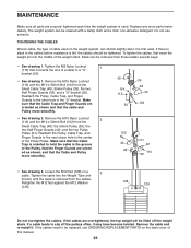
.... 42 114 115 50 39 48 42 102 102 42 48 51 42 114 39 • See drawing 3. If the cables are overtightened, the top weight will be lifted off the pulleys often, it . Tighten the M8 Nylon Locknut 1 (115) that the Finger Guards are orient- Retighten the M12 Nut against... Guards (42), and the two Pulley Plates (51). Reattach the Pulley, Cable Trap, and Finger Guards to the center of a cable to slip off the weight stack. Make sure that the Cable Trap is oriented to hold the cable in the cables before resistance is slack in the groove of the...
.... 42 114 115 50 39 48 42 102 102 42 48 51 42 114 39 • See drawing 3. If the cables are overtightened, the top weight will be lifted off the pulleys often, it . Tighten the M8 Nylon Locknut 1 (115) that the Finger Guards are orient- Retighten the M12 Nut against... Guards (42), and the two Pulley Plates (51). Reattach the Pulley, Cable Trap, and Finger Guards to the center of a cable to slip off the weight stack. Make sure that the Cable Trap is oriented to hold the cable in the cables before resistance is slack in the groove of the...

English Manual
Page 30
..., such as one day of rest. Toning You can tone your muscles by pushing them close to session. Rest for 1 minute after each set . Weight Loss To lose weight, use a low amount of resistance and increase the number of repetitions in two ways: • by changing the amount of resistance used •...
..., such as one day of rest. Toning You can tone your muscles by pushing them close to session. Rest for 1 minute after each set . Weight Loss To lose weight, use a low amount of resistance and increase the number of repetitions in two ways: • by changing the amount of resistance used •...

English Manual
Page 31
... Rest for three minutes after each set for a muscle building workout. • Rest for one minute after each set for a weight loss workout. Include stretches for both your everyday life. Remember, the key to achieving the greatest results is an effective way to ...Sartorius (front of every month. Anterior Deltoid (shoulder) M. Move slowly as you stretch and do not bounce. Ease into each set. Record your weight and key body measurements at the end of sets and repetitions completed. Latissimus Dorsi (mid back) T. Posterior Deltoid (shoulder) R. STAYING MOTIVATED For ...
... Rest for three minutes after each set for a muscle building workout. • Rest for one minute after each set for a weight loss workout. Include stretches for both your everyday life. Remember, the key to achieving the greatest results is an effective way to ...Sartorius (front of every month. Anterior Deltoid (shoulder) M. Move slowly as you stretch and do not bounce. Ease into each set. Record your weight and key body measurements at the end of sets and repetitions completed. Latissimus Dorsi (mid back) T. Posterior Deltoid (shoulder) R. STAYING MOTIVATED For ...
English Manual
Page 34
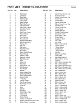
...Backrest Frame 28 1 Right Backrest 29 2 Seat 30 1 Knee Pad 31 2 Pad Tube 32 4 Small Foam Pad 33 1 Left Backrest 34 2 Top Weight 35 18 Weight 36 1 Long Weight Tube 37 1 Left Upright Plate 38 1 Rear Upright Plate 39 24 90mm Pulley 40 7 "V"-pulley 41 2 115mm Pulley 42 32 Half Finger Guard...Cap 56mm Round Inner Cap Foam Cap Arm Bushing 50mm Outer Cap 32mm Round Inner Cap Dip Arm Cap 25mm Outer Cap Cross Brace Weight Bumper Weight Tube Bumper Dip Assist Latch Right Stack Cable Press Cable Leg Lever Cable Lat Cable Ab Cable M10 x 110mm Bolt 40mm Spacer 12mm...
...Backrest Frame 28 1 Right Backrest 29 2 Seat 30 1 Knee Pad 31 2 Pad Tube 32 4 Small Foam Pad 33 1 Left Backrest 34 2 Top Weight 35 18 Weight 36 1 Long Weight Tube 37 1 Left Upright Plate 38 1 Rear Upright Plate 39 24 90mm Pulley 40 7 "V"-pulley 41 2 115mm Pulley 42 32 Half Finger Guard...Cap 56mm Round Inner Cap Foam Cap Arm Bushing 50mm Outer Cap 32mm Round Inner Cap Dip Arm Cap 25mm Outer Cap Cross Brace Weight Bumper Weight Tube Bumper Dip Assist Latch Right Stack Cable Press Cable Leg Lever Cable Lat Cable Ab Cable M10 x 110mm Bolt 40mm Spacer 12mm...
English Manual
Page 35
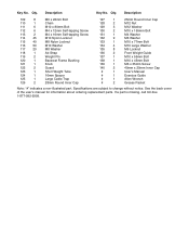
... M4 x 12mm Self-tapping Screw M4 x 16mm Self-tapping Screw M10 Nylon Locknut M8 Nylon Locknut M10 Washer M8 Washer Ab Strap Weight Pin Backrest Frame Bushing Knob Guard Short Weight Tube 16mm Spacer Large Cable Trap 28mm Round Inner Cap 127 1 128 2 129 3 130 2 131 1 132 9 133 1 ... 1 # 1 # 2 25mm Round Inner Cap M12 Nut M12 Washer M10 x 155mm Bolt M4 Washer M6 Washer M10 x 77mm Bolt M10 Large Washer M6 Locknut Front Weight Guide M10 x 55mm Bolt M10 x 45mm Bolt M6 x 35mm Screw 40mm x 20mm Inner Cap User's Manual Exercise Guide Allen Wrench Grease Packet Note: "#" indicates a ...
... M4 x 12mm Self-tapping Screw M4 x 16mm Self-tapping Screw M10 Nylon Locknut M8 Nylon Locknut M10 Washer M8 Washer Ab Strap Weight Pin Backrest Frame Bushing Knob Guard Short Weight Tube 16mm Spacer Large Cable Trap 28mm Round Inner Cap 127 1 128 2 129 3 130 2 131 1 132 9 133 1 ... 1 # 1 # 2 25mm Round Inner Cap M12 Nut M12 Washer M10 x 155mm Bolt M4 Washer M6 Washer M10 x 77mm Bolt M10 Large Washer M6 Locknut Front Weight Guide M10 x 55mm Bolt M10 x 45mm Bolt M6 x 35mm Screw 40mm x 20mm Inner Cap User's Manual Exercise Guide Allen Wrench Grease Packet Note: "#" indicates a ...

English Manual
Page 40
... rights which vary from the date of charge. Sears, Roebuck and Co., Dept 817WA, Hoffman Estates, IL 60179 Part No. 217807 R0804A Printed in this WEIGHT SYSTEM EXERCISER, contact the nearest Sears Service Center throughout the United States and Sears will repair or replace the... WEIGHT SYSTEM EXERCISER, free of purchase, if failure occurs due to state. This warranty does not apply when the WEIGHT SYSTEM EXERCISER is used commercially or for rental purposes. FULL 90-DAY WARRANTY For 90 days...
... rights which vary from the date of charge. Sears, Roebuck and Co., Dept 817WA, Hoffman Estates, IL 60179 Part No. 217807 R0804A Printed in this WEIGHT SYSTEM EXERCISER, contact the nearest Sears Service Center throughout the United States and Sears will repair or replace the... WEIGHT SYSTEM EXERCISER, free of purchase, if failure occurs due to state. This warranty does not apply when the WEIGHT SYSTEM EXERCISER is used commercially or for rental purposes. FULL 90-DAY WARRANTY For 90 days...


