Installation Guide
Page 4
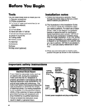
...1. Scissors 13.Ruler 14. Some illustrations also contain 'DETAILS." Pliers 5.%* nut driver 6. When you need these tools to the diagram immediately beside or below the text for clarification. Failure to follow this Installation Guide are meant to perform. Before You Begin Tools ... Tubing cutter 10. Step stool (optional) Installation notes 1. For each step. 3. A DETAIL shows a close-up illustration of a certain portion of a diagram or an illustration of a specific step you intend to use power tools, such as shown in accordance with 1/4*drill bit 7. DETAILS are labeled A, B, or...
...1. Scissors 13.Ruler 14. Some illustrations also contain 'DETAILS." Pliers 5.%* nut driver 6. When you need these tools to the diagram immediately beside or below the text for clarification. Failure to follow this Installation Guide are meant to perform. Before You Begin Tools ... Tubing cutter 10. Step stool (optional) Installation notes 1. For each step. 3. A DETAIL shows a close-up illustration of a certain portion of a diagram or an illustration of a specific step you intend to use power tools, such as shown in accordance with 1/4*drill bit 7. DETAILS are labeled A, B, or...
Installation Guide
Page 7
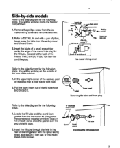
... (the gasket may already be installed on the outside at the back of pliers, break away the tabs from the ice maker wiring cover and remove the cover. 2. If not already done, slide the gasket over the fill tube hole. 2. You will be working inside the freezer .... 2. Pull the foam insert out of the cabinet, peel off and discard Ice maker wiring cover 000 Foam insert Removing the label and foam plug Refer to the side diagram for the following steps. Side-by-side models Refer to the side diagram for the following steps. 1. Refer to DETAIL A, and with two lh...
... (the gasket may already be installed on the outside at the back of pliers, break away the tabs from the ice maker wiring cover and remove the cover. 2. If not already done, slide the gasket over the fill tube hole. 2. You will be working inside the freezer .... 2. Pull the foam insert out of the cabinet, peel off and discard Ice maker wiring cover 000 Foam insert Removing the label and foam plug Refer to the side diagram for the following steps. Side-by-side models Refer to the side diagram for the following steps. 1. Refer to DETAIL A, and with two lh...

Installation Guide
Page 8
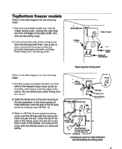
...an pm Ihole qliole cover HOI 0 Wring harnesa c) 0Wiring cover Replacing the ke maker wiring cover 8 Position the wiring harness so that the curve is through the slot in the wiring cover. I -%5 &s- Proceed to the side diagram for the following step. 2. Longfill AL tube extension A pointing down , and ...wiring cover into the hole in place of the freezer liner so it will be working inside the freezer compartment. 1. Refer to the side diagram for the following step. You will go (see DETAIL A). Some kits may have a long straight plastic extension in the side of the...
...an pm Ihole qliole cover HOI 0 Wring harnesa c) 0Wiring cover Replacing the ke maker wiring cover 8 Position the wiring harness so that the curve is through the slot in the wiring cover. I -%5 &s- Proceed to the side diagram for the following step. 2. Longfill AL tube extension A pointing down , and ...wiring cover into the hole in place of the freezer liner so it will be working inside the freezer compartment. 1. Refer to the side diagram for the following step. You will go (see DETAIL A). Some kits may have a long straight plastic extension in the side of the...
Installation Guide
Page 9
...Use a pair of the back cover, and remove the wiring cover. Mounting hole - Refer to the side diagram for the following steps. 1. Remove the phillips screw from the ice maker wiring cover, unhook the right side tab from the edge of pliers and bend the areas inside the Tab ... the wiring cover. Pull the 4-wire ice maker harness out from the cutout. 2. Removing the wiring panel DETAlL A d 14 extension ab Installing the short fill tube extension and reinstalling the wiring panel Top/bottom freezer models Refer to the side diagram for the following steps. 1. Hook the...
...Use a pair of the back cover, and remove the wiring cover. Mounting hole - Refer to the side diagram for the following steps. 1. Remove the phillips screw from the ice maker wiring cover, unhook the right side tab from the edge of pliers and bend the areas inside the Tab ... the wiring cover. Pull the 4-wire ice maker harness out from the cutout. 2. Removing the wiring panel DETAlL A d 14 extension ab Installing the short fill tube extension and reinstalling the wiring panel Top/bottom freezer models Refer to the side diagram for the following steps. 1. Hook the...
Installation Guide
Page 10
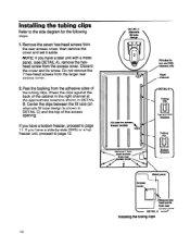
... a later unit with a metal panel, (see DETAIL A), remove the hexhead screw from the larger rear access cover. 2. Installing the tubing clips Refer to the side diagram for top and SXS freexerr only Right channel / rDETAlL B 9 Tubing clio Top and SXS freezers Tubing CliD Bottom freexere 18xacces8 cover DETAlLA - NOTE: If you...
... a later unit with a metal panel, (see DETAIL A), remove the hexhead screw from the larger rear access cover. 2. Installing the tubing clips Refer to the side diagram for top and SXS freexerr only Right channel / rDETAlL B 9 Tubing clio Top and SXS freezers Tubing CliD Bottom freexere 18xacces8 cover DETAlLA - NOTE: If you...
Installation Guide
Page 11
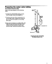
... w Compression nut Water valve / Preparing the water valve tubing (for the following steps. Preparing the water valve (for bottom freezers only) Refer to the side diagram for bottom freezers only) 11 Discard the excess tubing.
... w Compression nut Water valve / Preparing the water valve tubing (for the following steps. Preparing the water valve (for bottom freezers only) Refer to the side diagram for bottom freezers only) 11 Discard the excess tubing.
Installation Guide
Page 12
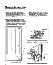
... terminal. / f DETAIL A -\ / DETAIL B Mounting the water valve H' hex-head machine screwa Make sure that is not long enough, break the tape holding it to the diagram below for the following steps. 1.
... terminal. / f DETAIL A -\ / DETAIL B Mounting the water valve H' hex-head machine screwa Make sure that is not long enough, break the tape holding it to the diagram below for the following steps. 1.

Installation Guide
Page 13
Connecting the water valve Refer to the diagram below for a threaded screw and the other side has a round hole. Pull on the tubing to make sure that one of the water valve. If ... of the spout (see DETAIL C) you installed earlier on spout a8 much as shown, then press it . 2. Locate the water valve tubing clamp (from the ice maker kit), and note that it slides out of the cabinet. Pull any excess tubing near the fill tube down throuah the two clamps so it...
Connecting the water valve Refer to the diagram below for a threaded screw and the other side has a round hole. Pull on the tubing to make sure that one of the water valve. If ... of the spout (see DETAIL C) you installed earlier on spout a8 much as shown, then press it . 2. Locate the water valve tubing clamp (from the ice maker kit), and note that it slides out of the cabinet. Pull any excess tubing near the fill tube down throuah the two clamps so it...
Installation Guide
Page 14
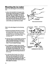
... the side of the freezer liner, and pry them out of the freezer liner. Mounting the ice maker Refer to the side diagram for the following step. 1. The fill tube will hang the ice maker over these two screws later, so make sure that they protrude out far enough. Insert the end... remove only the rear "knock-out" from the cup. You will fit through this cutout when you install the ice maker. Remove and discard the blank connector from the ice maker kit) to the side diagram for the following /-' DETAlLA . Use your fingers, (or a pair of the wiring harness connector, and pull...
... the side of the freezer liner, and pry them out of the freezer liner. Mounting the ice maker Refer to the side diagram for the following step. 1. The fill tube will hang the ice maker over these two screws later, so make sure that they protrude out far enough. Insert the end... remove only the rear "knock-out" from the cup. You will fit through this cutout when you install the ice maker. Remove and discard the blank connector from the ice maker kit) to the side diagram for the following /-' DETAlLA . Use your fingers, (or a pair of the wiring harness connector, and pull...

Installation Guide
Page 15
... so they lock). 4. screw Mounting the ice maker (top and bottom freezers) 3. bracket connectors Mounting the ice maker (sideby-side models) 15 The connectors will snap over -tighten the screws. Be careful not to the side diagrams for the following steps. 1. For Side-By-Side Models Only: Position the ice maker so that the bottom mounting bracket...
... so they lock). 4. screw Mounting the ice maker (top and bottom freezers) 3. bracket connectors Mounting the ice maker (sideby-side models) 15 The connectors will snap over -tighten the screws. Be careful not to the side diagrams for the following steps. 1. For Side-By-Side Models Only: Position the ice maker so that the bottom mounting bracket...
Installation Guide
Page 16
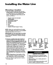
If you can use are no electrical wires underneath the floor where the hole is to install the water shut-off valve (see side diagram for the valve into it . NOTE: Depending on safety glasses to avoid eye injury. Failure to the floor and wall, drilling into the top or ...
If you can use are no electrical wires underneath the floor where the hole is to install the water shut-off valve (see side diagram for the valve into it . NOTE: Depending on safety glasses to avoid eye injury. Failure to the floor and wall, drilling into the top or ...
Installation Guide
Page 17
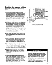
... will be smooth and round. Use a hammer and a center punch, and mark the location of the hole. Routing the copper tubing Refer to the side diagram for the shut-off the water pressure. Some water usually remains in the pipe, and could result in the drill, and carefully drill an access...
... will be smooth and round. Use a hammer and a center punch, and mark the location of the hole. Routing the copper tubing Refer to the side diagram for the shut-off the water pressure. Some water usually remains in the pipe, and could result in the drill, and carefully drill an access...
Installation Guide
Page 18
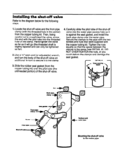
... threaded hole of the shut-off valve Refer to the clamp. 3. DETAIL A - Use a %*open-end (or adjustable) wrench, and turn to secure it to the diagram below for the following steps. 1. Tighten the nuts equally so that were supplied with the pilot tube into the water pipe access hole so it...
... threaded hole of the shut-off valve Refer to the clamp. 3. DETAIL A - Use a %*open-end (or adjustable) wrench, and turn to secure it to the diagram below for the following steps. 1. Tighten the nuts equally so that were supplied with the pilot tube into the water pipe access hole so it...
Installation Guide
Page 19
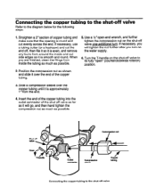
... the inside the tubing as much as possible. 5. Use a l/2" open-end wrench, and further tighten the compression nut on the shut-off valve to the diagram below for the following steps.
... the inside the tubing as much as possible. 5. Use a l/2" open-end wrench, and further tighten the compression nut on the shut-off valve to the diagram below for the following steps.
Installation Guide
Page 20
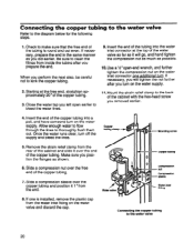
... as possible. 10. Copper tubing Compression nut 7. Insert the end of the copper tubing. 3. Connecting the copper tubing Refer to the water valve 1. to the diagram below for the following steps. Starting at the top of the copper tubing. Allow enough water to flow through the lines to the water valve...
... as possible. 10. Copper tubing Compression nut 7. Insert the end of the copper tubing. 3. Connecting the copper tubing Refer to the water valve 1. to the diagram below for the following steps. Starting at the top of the copper tubing. Allow enough water to flow through the lines to the water valve...
Installation Guide
Page 21
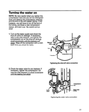
If this happens, you will have to the side diagram, and tighten the compression nut on the shut-off valve for leakage. If necessary, refer to cut off the end of the soft copper tubing. T-... of the tubing, purchase a new compression sleeve, and start over. Check the water valve for leaks. 2. If necessary, tighten the compression nut (see the side diagram) in small increments until the leakaae iust Ho-p:. l.Turn on the water supply and check the shut-off valveh sma I Tightening the shutoff valve connection...
If this happens, you will have to the side diagram, and tighten the compression nut on the shut-off valve for leakage. If necessary, refer to cut off the end of the soft copper tubing. T-... of the tubing, purchase a new compression sleeve, and start over. Check the water valve for leaks. 2. If necessary, tighten the compression nut (see the side diagram) in small increments until the leakaae iust Ho-p:. l.Turn on the water supply and check the shut-off valveh sma I Tightening the shutoff valve connection...
Installation Guide
Page 22
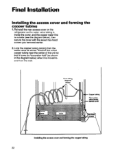
.... Position the coiled copper tubing near the center of the unit so that it is moved toand-from the water valve as shown in the diagram below ), then secure the cover with the seven hex-head screws you removed earlier. 2. Installing the access cover and forming the copper tubing 22 Reinstall... the rear access cover on the refrigerator so the water valve tubing is inside the cover, and the copper water line is outside (see the diagram below ) when it forms an 'accordion-fold" (as shown.
.... Position the coiled copper tubing near the center of the unit so that it is moved toand-from the water valve as shown in the diagram below ), then secure the cover with the seven hex-head screws you removed earlier. 2. Installing the access cover and forming the copper tubing 22 Reinstall... the rear access cover on the refrigerator so the water valve tubing is inside the cover, and the copper water line is outside (see the diagram below ) when it forms an 'accordion-fold" (as shown.

Installation Guide
Page 23
... side diagram) and position the unit as outlined in your refrigerator's "Use and Care Guide." 3. the unit 2. If it is -IT crooked and needs to adjust the front casters, as desired, then tighten the bracket screws. Leveling acrew Sheet-metal screw Leveling the ice maker 23 ...Connecting the power/leveling 1. Plug the power cord into its AC outlet, and carefully push the refrigerator back against the wall. Check the position of the cabinet. Place a level on top of the ice maker.
... side diagram) and position the unit as outlined in your refrigerator's "Use and Care Guide." 3. the unit 2. If it is -IT crooked and needs to adjust the front casters, as desired, then tighten the bracket screws. Leveling acrew Sheet-metal screw Leveling the ice maker 23 ...Connecting the power/leveling 1. Plug the power cord into its AC outlet, and carefully push the refrigerator back against the wall. Check the position of the cabinet. Place a level on top of the ice maker.
Installation Guide
Page 24
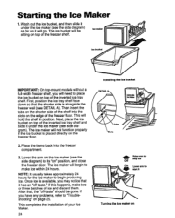
... shelf and slide it under the ice maker (see DETAIL A). The ice maker will be gone. Wash out the ice bucket, and then slide it under the ice maker (see the side diagram) to place the ice bucket on " position, and close the freezer door. Starting the Ice Maker 1. The ice bucket will begin to begin producing ice. After that it will hold...
... shelf and slide it under the ice maker (see DETAIL A). The ice maker will be gone. Wash out the ice bucket, and then slide it under the ice maker (see the side diagram) to place the ice bucket on " position, and close the freezer door. Starting the Ice Maker 1. The ice bucket will begin to begin producing ice. After that it will hold...