Installation Guide
Page 1
Y Table of Contents (complete 2 Requesting of Service Assistance 2 1 cmpoftant Inf of mation ...3 Before You Begin .......... 4 Installing the Ice Maker 6 1 Installing the I Water une 16 Final installation .,........ 22 Starting the ice Maker 24 TrOubleshOOting .......... 25 MODULAR ICEMAKER KIT PART NO. 2155462 Rev. A
Y Table of Contents (complete 2 Requesting of Service Assistance 2 1 cmpoftant Inf of mation ...3 Before You Begin .......... 4 Installing the Ice Maker 6 1 Installing the I Water une 16 Final installation .,........ 22 Starting the ice Maker 24 TrOubleshOOting .......... 25 MODULAR ICEMAKER KIT PART NO. 2155462 Rev. A
Installation Guide
Page 2
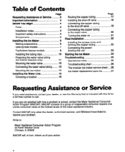
..., inform us of Contents Page Requesting Assistance or Service 2 important Information 3 Before You Begin 4 Tools 4 Installation notes 4 Important safety instructions 4 Components 5 installing the ice Maker 6 Making preparations 6 Side-by-side models 7 Top/bottom freezer models 9 Installing the tubing clips 10 Preparing the water valve tubing (for bottom freezers only 11 Mounting the water... with how a problem is solved, contact the Major Appliance Consumer Action Program (MACAP). Contact MACAP only when the dealer, authorized servicer, and Whirlpool have failed to call.
..., inform us of Contents Page Requesting Assistance or Service 2 important Information 3 Before You Begin 4 Tools 4 Installation notes 4 Important safety instructions 4 Components 5 installing the ice Maker 6 Making preparations 6 Side-by-side models 7 Top/bottom freezer models 9 Installing the tubing clips 10 Preparing the water valve tubing (for bottom freezers only 11 Mounting the water... with how a problem is solved, contact the Major Appliance Consumer Action Program (MACAP). Contact MACAP only when the dealer, authorized servicer, and Whirlpool have failed to call.
Installation Guide
Page 3
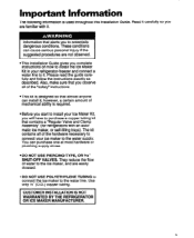
... will have to purchase a copper tubing kit that alerts you complete instructions on how to install the Ice Maker Kit in your ice maker to potentially dangerous conditions. Use only '!4" (O.D.) copper tubing. ICUSTOMER INSTALLATION IS NOT WARRANTED BY THE REFRIGERATOR OR ICE MAKER MANUFACTURER. Read it . information that contains a "Regular Valve and Clamp Assembly" (for refrigerators with it...
... will have to purchase a copper tubing kit that alerts you complete instructions on how to install the Ice Maker Kit in your ice maker to potentially dangerous conditions. Use only '!4" (O.D.) copper tubing. ICUSTOMER INSTALLATION IS NOT WARRANTED BY THE REFRIGERATOR OR ICE MAKER MANUFACTURER. Read it . information that contains a "Regular Valve and Clamp Assembly" (for refrigerators with it...
Installation Guide
Page 4
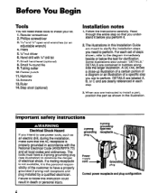
...step so that the AC receptacle is properly grounded in accordance with 1/4*drill bit 7. Center punch 11. Step stool (optional) Installation notes 1. Some illustrations also contain 'DETAILS." Failure to perform. Hand drill with the National Electrical Code (ANSVNFPA 70) and ...3-prong groundingtype wall receptacle Correct power receptacle and plug configuration A DETAILS are labeled A, B, or C and are meant to clarify the installation steps you are contained in the illustration. The tools must have a 3-prong grounding plug (see illustration) to have a properly grounded ...
...step so that the AC receptacle is properly grounded in accordance with 1/4*drill bit 7. Center punch 11. Step stool (optional) Installation notes 1. Some illustrations also contain 'DETAILS." Failure to perform. Hand drill with the National Electrical Code (ANSVNFPA 70) and ...3-prong groundingtype wall receptacle Correct power receptacle and plug configuration A DETAILS are labeled A, B, or C and are meant to clarify the installation steps you are contained in the illustration. The tools must have a 3-prong grounding plug (see illustration) to have a properly grounded ...
Installation Guide
Page 5
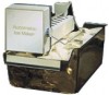
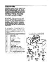
... to the water supply. COMPONENT ILLUSTRATIONS IMPORTANT: When you connect it . It has been factory-installed and leak-tested. Do not discard any of the components. The KEY numbers correspond to help you account for the Ice Maker, a replacement parts list is provided on a table where they can be easily identified and located...
... to the water supply. COMPONENT ILLUSTRATIONS IMPORTANT: When you connect it . It has been factory-installed and leak-tested. Do not discard any of the components. The KEY numbers correspond to help you account for the Ice Maker, a replacement parts list is provided on a table where they can be easily identified and located...
Installation Guide
Page 6
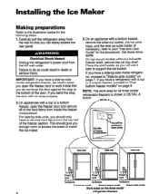
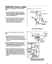
... with a top or a bottom freezer, open the freezer door to support the ice bucket. Carefully pull the refrigerator away from the top half of the door. Installing the Ice Maker Making preparations Refer to the illustration below . IMPORTANT: If you enough room to ...access the areas to install the ice maker. 3.On an appliance with a top or a bottom freezer, proceed ...
... with a top or a bottom freezer, open the freezer door to support the ice bucket. Carefully pull the refrigerator away from the top half of the door. Installing the Ice Maker Making preparations Refer to the illustration below . IMPORTANT: If you enough room to ...access the areas to install the ice maker. 3.On an appliance with a top or a bottom freezer, proceed ...
Installation Guide
Page 7
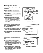
...Insert tab into slot Break off the label that is over the end of pliers, break away the tabs from the ice maker wiring cover and remove the cover. 2. spout / Foam I gasket I I Installing the fill tube/gasket 7 You will be working inside the freezer compartment. 1. Refer to DETAIL A, and with a... Pull the foam insert out of the cabinet, peel off and discard Ice maker wiring cover 000 Foam insert Removing the label and foam plug Refer to the side diagram for the following steps. 1. You will be installed on the outside at the back of the refrigerator with two lh" ...
...Insert tab into slot Break off the label that is over the end of pliers, break away the tabs from the ice maker wiring cover and remove the cover. 2. spout / Foam I gasket I I Installing the fill tube/gasket 7 You will be working inside the freezer compartment. 1. Refer to DETAIL A, and with a... Pull the foam insert out of the cabinet, peel off and discard Ice maker wiring cover 000 Foam insert Removing the label and foam plug Refer to the side diagram for the following steps. 1. You will be installed on the outside at the back of the refrigerator with two lh" ...

Installation Guide
Page 8
... end over the fill tube as far as it is pointing down w- an pm Ihole qliole cover HOI 0 Wring harnesa c) 0Wiring cover Replacing the ke maker wiring cover 8 Position the long aluminum fill tube extension so that it will go . I -%5 &s- Secure the wiring cover with the phillips screw you removed... earlier. Press the pin on page 10. Refer to the side diagram for the following step. Install the plastic extension by sliding it over the fill tube as far as it locks into the freezer liner slot. Proceed to...
... end over the fill tube as far as it is pointing down w- an pm Ihole qliole cover HOI 0 Wring harnesa c) 0Wiring cover Replacing the ke maker wiring cover 8 Position the long aluminum fill tube extension so that it will go . I -%5 &s- Secure the wiring cover with the phillips screw you removed... earlier. Press the pin on page 10. Refer to the side diagram for the following step. Install the plastic extension by sliding it over the fill tube as far as it locks into the freezer liner slot. Proceed to...
Installation Guide
Page 9
... cover into the slot in the back cover of the back cover, and remove the wiring cover. Phillips 2. Pull the 4-wire ice maker harness out from the cutout. 2. Refer to DETAIL B and install the wiring cover over the fill tube with the phillips screw you removed earlier. Removing the wiring panel DETAlL A d 14...
... cover into the slot in the back cover of the back cover, and remove the wiring cover. Phillips 2. Pull the 4-wire ice maker harness out from the cutout. 2. Refer to DETAIL B and install the wiring cover over the fill tube with the phillips screw you removed earlier. Removing the wiring panel DETAlL A d 14...
Installation Guide
Page 10
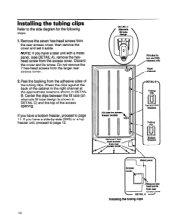
... unit with a metal panel, (see DETAIL A), remove the hexhead screw from the rear access cover, then remove the cover and set it aside. Installing the tubing clips Refer to the side diagram for top and SXS freexerr only Right channel / rDETAlL B 9 Tubing clio Top and SXS freezers Tubing ...CliD Bottom freexere 18xacces8 cover DETAlLA - Discard the cover and its screw. Installing the tubing clips 10 Remove the seven hex-head screws from the access cover. Press the clips against the back of the cabinet in the...
... unit with a metal panel, (see DETAIL A), remove the hexhead screw from the rear access cover, then remove the cover and set it aside. Installing the tubing clips Refer to the side diagram for top and SXS freexerr only Right channel / rDETAlL B 9 Tubing clio Top and SXS freezers Tubing ...CliD Bottom freexere 18xacces8 cover DETAlLA - Discard the cover and its screw. Installing the tubing clips 10 Remove the seven hex-head screws from the access cover. Press the clips against the back of the cabinet in the...

Installation Guide
Page 13
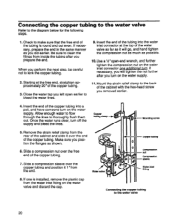
... the following steps. 1. Refer to DETAIL 6, and slide the end of the cabinet. You will connect the free end of the spout (see DETAIL C) you installed earlier on the back of the tubing into the water valve tubing. Slide over the end of the tubing later. 6. Pull on spout a8 much... Insert tubinf into spout a8 far a8 poesible I = 'Tighten\ wrew on the tubing to the fill tube Locate the water valve tubing clamp (from the ice maker kit), and note that it back in DETAIL A and pull the plastic insert out of the water valve.
... the following steps. 1. Refer to DETAIL 6, and slide the end of the cabinet. You will connect the free end of the spout (see DETAIL C) you installed earlier on the back of the tubing into the water valve tubing. Slide over the end of the tubing later. 6. Pull on spout a8 much... Insert tubinf into spout a8 far a8 poesible I = 'Tighten\ wrew on the tubing to the fill tube Locate the water valve tubing clamp (from the ice maker kit), and note that it back in DETAIL A and pull the plastic insert out of the water valve.
Installation Guide
Page 14
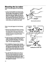
...easier), and remove only the rear "knock-out" from the cup. You will fit through this cutout when you install the ice maker. For Top/Bottom Freezers Only: Partially install two %" hex-head sheet-metal screws into the two top mounting holes (shown in the side of the freezer...Make sure that they protrude out far enough. The fill tube will hang the ice maker over tab I Blank connector a (remove and discard) Installing Wring harness -1 connector the ice maker clips 4. You can discard the plugs. 3. Look at the ice maker's fill cup and note that the rear of the cup has a "U" shaped...
...easier), and remove only the rear "knock-out" from the cup. You will fit through this cutout when you install the ice maker. For Top/Bottom Freezers Only: Partially install two %" hex-head sheet-metal screws into the two top mounting holes (shown in the side of the freezer...Make sure that they protrude out far enough. The fill tube will hang the ice maker over tab I Blank connector a (remove and discard) Installing Wring harness -1 connector the ice maker clips 4. You can discard the plugs. 3. Look at the ice maker's fill cup and note that the rear of the cup has a "U" shaped...

Installation Guide
Page 15
... following steps. 1. For Side-By-Side Models Only: Position the ice maker so that the mounting clips snap over the tabs and lock into place (you installed earlier. Refer to over-tighten the screws. screw Mounting the ice maker (top and bottom freezers) 3. Position the ice maker inside the freezer compartment and connect its top and bottom...
... following steps. 1. For Side-By-Side Models Only: Position the ice maker so that the mounting clips snap over the tabs and lock into place (you installed earlier. Refer to over-tighten the screws. screw Mounting the ice maker (top and bottom freezers) 3. Position the ice maker inside the freezer compartment and connect its top and bottom...
Installation Guide
Page 16
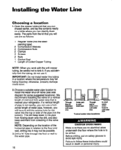
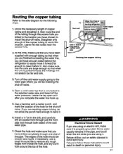
... down onto the drill, and also keep sediment from the kit that is not nearby, you will have to follow these instructions could occur. 2. Installing the Water Line Choosing a location 1. Choose a suitable water pipe location to the floor and wall, drilling into the top or side of water .... The parts from collecting in death or personal injury. IMPORTANT: Do not install water line tubing in relation to install the water shut-off valve (see side diagram for the valve into it . We recommend installing the valve on the location of Coiled Copper Tubing NOTE: When you can ...
... down onto the drill, and also keep sediment from the kit that is not nearby, you will have to follow these instructions could occur. 2. Installing the Water Line Choosing a location 1. Choose a suitable water pipe location to the floor and wall, drilling into the top or side of water .... The parts from collecting in death or personal injury. IMPORTANT: Do not install water line tubing in relation to install the water shut-off valve (see side diagram for the valve into it . We recommend installing the valve on the location of Coiled Copper Tubing NOTE: When you can ...
Installation Guide
Page 17
... usually remains in the drill, and carefully drill an access hole through just the front side (not through one side of the copper tubing to install the shut-off valve. Straighten only enough of the pipe. Leave the rest coiled near the access hole. 2.At this location. Leave the tap open... pipe and bleed off valve. 4. Open a cold water tap that the coils are using it is connected to bend it . The edges of the hole. Install a l/4* bit in the pipe, and could result in death or personal injury. Failure to remove any rough edges from inside the hole, and any burrs...
... usually remains in the drill, and carefully drill an access hole through just the front side (not through one side of the copper tubing to install the shut-off valve. Straighten only enough of the pipe. Leave the rest coiled near the access hole. 2.At this location. Leave the tap open... pipe and bleed off valve. 4. Open a cold water tap that the coils are using it is connected to bend it . The edges of the hole. Install a l/4* bit in the pipe, and could result in death or personal injury. Failure to remove any rough edges from inside the hole, and any burrs...
Installation Guide
Page 18
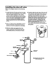
... crossthread the valve, screw the end with the copper tubing kit. Hand-tighten the valve as far as it is against the seal gasket, and install the back pipe clamp over the pilot tube (the unthreaded portion) of the clamp. I . Carefully slide the pilot tube of the shut-off valve and... to the water pipe Slide the rubber seal gasket (from the copper tubing kit. Secure the clamps to the diagram below for the following steps. 1. Installing the shut-off valve. 4. Locate the shut-off valve into the threaded hole of the shut-off valve Refer to the pipe with the two...
... crossthread the valve, screw the end with the copper tubing kit. Hand-tighten the valve as far as it is against the seal gasket, and install the back pipe clamp over the pilot tube (the unthreaded portion) of the clamp. I . Carefully slide the pilot tube of the shut-off valve and... to the water pipe Slide the rubber seal gasket (from the copper tubing kit. Secure the clamps to the diagram below for the following steps. 1. Installing the shut-off valve. 4. Locate the shut-off valve into the threaded hole of the shut-off valve Refer to the pipe with the two...
Installation Guide
Page 20
... as you removed earlier. 4. Make sure you perform the next step, be careful not to make sure that the free end of the tubing is installed, remove the plastic cap from the rear of the copper tubing. Slide a compression sleeve over the free end of the cabinet and slide it 1 "from...
... as you removed earlier. 4. Make sure you perform the next step, be careful not to make sure that the free end of the tubing is installed, remove the plastic cap from the rear of the copper tubing. Slide a compression sleeve over the free end of the cabinet and slide it 1 "from...
Installation Guide
Page 22
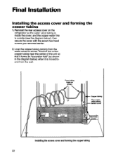
Final Installation Installing the access cover and forming the copper tubing 1. Reinstall the rear access cover on the refrigerator so the water valve tubing is inside the cover, ... valve as shown. Form tubing loops as shown in the diagram below ), then secure the cover with the seven hex-head screws you removed earlier. 2. Installing the access cover and forming the copper tubing 22 Loop the copper tubing coming from the wall. Copper tubing Place water valve tubing 7 behind cover...
Final Installation Installing the access cover and forming the copper tubing 1. Reinstall the rear access cover on the refrigerator so the water valve tubing is inside the cover, ... valve as shown. Form tubing loops as shown in the diagram below ), then secure the cover with the seven hex-head screws you removed earlier. 2. Installing the access cover and forming the copper tubing 22 Loop the copper tubing coming from the wall. Copper tubing Place water valve tubing 7 behind cover...
Installation Guide
Page 24
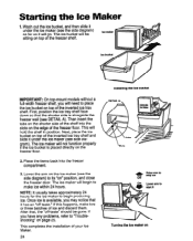
... shelf and slide it will be gone. Starting the Ice Maker 1. The ice bucket will go. Next, place the ice bucket on top of your Ice Maker. 24 Installing the ice bucket Raise arm to * stop ice off -taste" should be sitting on " position, and close the freezer door. The ice maker will need to 'Troubleshooting" on top of the freezer...
... shelf and slide it will be gone. Starting the Ice Maker 1. The ice bucket will go. Next, place the ice bucket on top of your Ice Maker. 24 Installing the ice bucket Raise arm to * stop ice off -taste" should be sitting on " position, and close the freezer door. The ice maker will need to 'Troubleshooting" on top of the freezer...
Installation Guide
Page 25
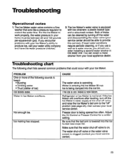
... consider installing a second water strainer in your service center should be between 20 and 120 pounds per-square-inch (psi). You can be cleaned by turning off valve is on. Troubleshooting chart The following sounds is being opened too often. Ice making ... a water source, you encounter problems with your Ice Maker. Refrigerator or Ice Maker is operating. CAUSE The water valve is not level. Freezer door is lowered into the ice bin. The Ice Maker's water valve is entering the Ice Maker fill cup. Not enough ice. Water is equipped with two strainers: a plastic...
... consider installing a second water strainer in your service center should be between 20 and 120 pounds per-square-inch (psi). You can be cleaned by turning off valve is on. Troubleshooting chart The following sounds is being opened too often. Ice making ... a water source, you encounter problems with your Ice Maker. Refrigerator or Ice Maker is operating. CAUSE The water valve is not level. Freezer door is lowered into the ice bin. The Ice Maker's water valve is entering the Ice Maker fill cup. Not enough ice. Water is equipped with two strainers: a plastic...