Installation Guide
Page 1
A Y Table of Contents (complete 2 Requesting of Service Assistance 2 1 cmpoftant Inf of mation ...3 Before You Begin .......... 4 Installing the Ice Maker 6 1 Installing the I Water une 16 Final installation .,........ 22 Starting the ice Maker 24 TrOubleshOOting .......... 25 MODULAR ICEMAKER KIT PART NO. 2155462 Rev.
A Y Table of Contents (complete 2 Requesting of Service Assistance 2 1 cmpoftant Inf of mation ...3 Before You Begin .......... 4 Installing the Ice Maker 6 1 Installing the I Water une 16 Final installation .,........ 22 Starting the ice Maker 24 TrOubleshOOting .......... 25 MODULAR ICEMAKER KIT PART NO. 2155462 Rev.
Installation Guide
Page 2
...experts that is solved, contact the Major Appliance Consumer Action Program (MACAP). Contact MACAP only when the dealer, authorized servicer, and Whirlpool have failed to resolve your action. 3 Write to: Major Appliance Consumer Action Program 20 North Wacker Drive Chicago, IL 60606 ...the copper tubing 22 Connecting the power/ leveling the unit 23 Starting the ice Maker 24 Troubleshooting 25 Operational notes 25 Troubleshooting chart 25 The modular ice maker service sheet .... 26 Ice maker replacement parts list 27 Requesting Assistance or Service If you are not satisfied with...
...experts that is solved, contact the Major Appliance Consumer Action Program (MACAP). Contact MACAP only when the dealer, authorized servicer, and Whirlpool have failed to resolve your action. 3 Write to: Major Appliance Consumer Action Program 20 North Wacker Drive Chicago, IL 60606 ...the copper tubing 22 Connecting the power/ leveling the unit 23 Starting the ice Maker 24 Troubleshooting 25 Operational notes 25 Troubleshooting chart 25 The modular ice maker service sheet .... 26 Ice maker replacement parts list 27 Requesting Assistance or Service If you are not satisfied with...
Installation Guide
Page 3
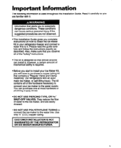
... to the water supply. You can install it . They reduce the flow of mechanical ability is used throughout this installation Guide. matic ice maker, or self-filling trays). Use only '!4" (O.D.) copper tubing. information that contains a "Regular Valve and Clamp Assembly" (for refrigerators ... the instructions exactly as described. Also, make sure that you complete instructions on how to install the Ice Maker Kit in your ice maker to it ; Important Information The following information is required. Read it . ICUSTOMER INSTALLATION IS NOT WARRANTED BY THE...
... to the water supply. You can install it . They reduce the flow of mechanical ability is used throughout this installation Guide. matic ice maker, or self-filling trays). Use only '!4" (O.D.) copper tubing. information that contains a "Regular Valve and Clamp Assembly" (for refrigerators ... the instructions exactly as described. Also, make sure that you complete instructions on how to install the Ice Maker Kit in your ice maker to it ; Important Information The following information is required. Read it . ICUSTOMER INSTALLATION IS NOT WARRANTED BY THE...
Installation Guide
Page 4
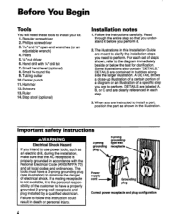
Phillips screwdriver 3. %6" and l/i' open-end wrenches (or an adjustable wrench) 4. Pliers 5.%* nut driver 6. Tubing cutter 10. Center punch 11. A DETAIL shows a close-up illustration of a certain portion of a diagram or an illustration of a specific step you need these tools to perform. Regular screwdriver 2. The tools must have a properly grounded 3-prong wall receptacle and plug installed by a qualified electrician. Hammer 12. DETAILS are clearly referenced in each set of the customer to follow this Installation Guide are meant to clarify the installation ...
Phillips screwdriver 3. %6" and l/i' open-end wrenches (or an adjustable wrench) 4. Pliers 5.%* nut driver 6. Tubing cutter 10. Center punch 11. A DETAIL shows a close-up illustration of a certain portion of a diagram or an illustration of a specific step you need these tools to perform. Regular screwdriver 2. The tools must have a properly grounded 3-prong wall receptacle and plug installed by a qualified electrician. Hammer 12. DETAILS are clearly referenced in each set of the customer to follow this Installation Guide are meant to clarify the installation ...
Installation Guide
Page 5
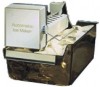
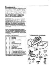
... page 27. KEY QTY. 1 1 2 1 3 1 4 1 5 1 6 1 7 1 8 2 9 2 10 1 11 1 12 4 13 2 14 2 DESCRIPTION Ice maker Ice bucket Water valve w/tubing Fill tube Gasket Short extension tube Long extension tube* ice maker clips* Tubing clips Metal water tube insert Water valve tubing clamp % ' hex-head sheet-metal screws N'hex-head machine... sheet-metal screws l For installation in the kit against the following list to the water supply. IMPORTANT: When you account for the Ice Maker, a replacement parts list is provided on a table where they can be easily identified and located. Do not discard any of the ...
... page 27. KEY QTY. 1 1 2 1 3 1 4 1 5 1 6 1 7 1 8 2 9 2 10 1 11 1 12 4 13 2 14 2 DESCRIPTION Ice maker Ice bucket Water valve w/tubing Fill tube Gasket Short extension tube Long extension tube* ice maker clips* Tubing clips Metal water tube insert Water valve tubing clamp % ' hex-head sheet-metal screws N'hex-head machine... sheet-metal screws l For installation in the kit against the following list to the water supply. IMPORTANT: When you account for the Ice Maker, a replacement parts list is provided on a table where they can be easily identified and located. Do not discard any of the ...
Installation Guide
Page 6
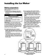
...you have a side-by -eide model Work areas on page 7. On top-mount models without a full-width freezer shelf, remove the ice tray shelf. Installing the Ice Maker Making preparations Refer to "Top/ bottom freezer models" on page 9. This should only have a refrigerator with a top or a bottom ...9 Power \ cpolrud g=_I' . For side-by -side model refrigerator-freezer, be careful when you enough room to access the areas to install the ice maker. 3.On an appliance with a top or a bottom freezer, open the freezer door to your "Use and Care Guide" for the following steps. ...
...you have a side-by -eide model Work areas on page 7. On top-mount models without a full-width freezer shelf, remove the ice tray shelf. Installing the Ice Maker Making preparations Refer to "Top/ bottom freezer models" on page 9. This should only have a refrigerator with a top or a bottom ...9 Power \ cpolrud g=_I' . For side-by -side model refrigerator-freezer, be careful when you enough room to access the areas to install the ice maker. 3.On an appliance with a top or a bottom freezer, open the freezer door to your "Use and Care Guide" for the following steps. ...
Installation Guide
Page 7
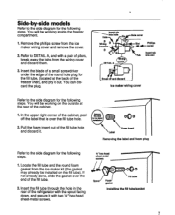
... break away the tabs from the wiring cover and discard them. 3. In the upper right corner of the cabinet, peel off and discard Ice maker wiring cover 000 Foam insert Removing the label and foam plug Refer to the side diagram for the following steps. You will be working on...I I Installing the fill tube/gasket 7 You will be working inside the freezer compartment. 1. Locate the fill tube and the round foam gasket from the ice maker wiring cover and remove the cover. 2. Refer to DETAIL A, and with two lh" hex-head sheet-metal screws. You can discard the plug. Insert the...
... break away the tabs from the wiring cover and discard them. 3. In the upper right corner of the cabinet, peel off and discard Ice maker wiring cover 000 Foam insert Removing the label and foam plug Refer to the side diagram for the following steps. You will be working on...I I Installing the fill tube/gasket 7 You will be working inside the freezer compartment. 1. Locate the fill tube and the round foam gasket from the ice maker wiring cover and remove the cover. 2. Refer to DETAIL A, and with two lh" hex-head sheet-metal screws. You can discard the plug. Insert the...

Installation Guide
Page 8
... end over the fill tube as far as it is pointing down w- an pm Ihole qliole cover HOI 0 Wring harnesa c) 0Wiring cover Replacing the ke maker wiring cover 8 You will go . Proceed to the side diagram for the following step. Position the wiring harness so that the curve is through the...
... end over the fill tube as far as it is pointing down w- an pm Ihole qliole cover HOI 0 Wring harnesa c) 0Wiring cover Replacing the ke maker wiring cover 8 You will go . Proceed to the side diagram for the following step. Position the wiring harness so that the curve is through the...
Installation Guide
Page 9
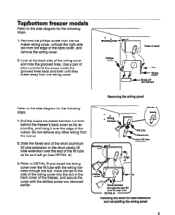
... lines. Removing the wiring panel DETAlL A d 14 extension ab Installing the short fill tube extension and reinstalling the wiring panel Pull the 4-wire ice maker harness out from the edge of the cutout. Slide the flared end of the short aluminum fill tube extension or the short plastic fill tube...wiring from the wiring cover. Top/bottom freezer models Refer to the side diagram for the following steps. 1. Remove the phillips screw from the ice maker wiring cover, unhook the right side tab from behind the freezer's back cover as far as it over the fill tube with the phillips ...
... lines. Removing the wiring panel DETAlL A d 14 extension ab Installing the short fill tube extension and reinstalling the wiring panel Pull the 4-wire ice maker harness out from the edge of the cutout. Slide the flared end of the short aluminum fill tube extension or the short plastic fill tube...wiring from the wiring cover. Top/bottom freezer models Refer to the side diagram for the following steps. 1. Remove the phillips screw from the ice maker wiring cover, unhook the right side tab from behind the freezer's back cover as far as it over the fill tube with the phillips ...
Installation Guide
Page 10
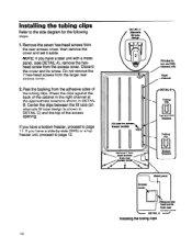
Do not remove the 7 hex-head screws from the rear access cover, then remove the cover and set it aside. If you have a bottom freezer, proceed to page 11. DETAlL C Fill tube for b freezer mode Fill tube for the following steps. 1. If you have a later unit with a metal panel, (see DETAIL A), remove the hexhead screw from the adhesive sides of the access opening. Remove the seven hex-head screws from the larger rear access cover. 2. Installing the tubing clips 10 Center the clips between the fill tube (an alternate fill tube design is shown in DETAIL B. Discard the ...
Do not remove the 7 hex-head screws from the rear access cover, then remove the cover and set it aside. If you have a bottom freezer, proceed to page 11. DETAlL C Fill tube for b freezer mode Fill tube for the following steps. 1. If you have a later unit with a metal panel, (see DETAIL A), remove the hexhead screw from the adhesive sides of the access opening. Remove the seven hex-head screws from the larger rear access cover. 2. Installing the tubing clips 10 Center the clips between the fill tube (an alternate fill tube design is shown in DETAIL B. Discard the ...
Installation Guide
Page 11
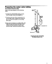
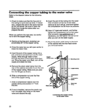
Discard the excess tubing. Use a pair of scissors or a hobby knife, and make an even cut across the water valve tubing at the top of the compression nut on the water valve, measure the tubing for 30: and mark the location on the tubing with a pen. 3. tubing 1. Untape the coiled flexible tubing coming from the water valve and straighten it. 2. CUT TUBING HERE I II MAKE AN EVEN CUT ACROSS w Compression nut Water valve / Preparing the water valve tubing (for the following steps. Preparing the water valve (for bottom freezers only) Refer to the side diagram for bottom freezers...
Discard the excess tubing. Use a pair of scissors or a hobby knife, and make an even cut across the water valve tubing at the top of the compression nut on the water valve, measure the tubing for 30: and mark the location on the tubing with a pen. 3. tubing 1. Untape the coiled flexible tubing coming from the water valve and straighten it. 2. CUT TUBING HERE I II MAKE AN EVEN CUT ACROSS w Compression nut Water valve / Preparing the water valve tubing (for the following steps. Preparing the water valve (for bottom freezers only) Refer to the side diagram for bottom freezers...
Installation Guide
Page 12
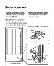
Locate the 2-pin water valve solenoid connector (with the wires at the lower right corner of the rear access (see DETAIL A). 3. You can position the connector with the brown and two white wires) that you tighten these two screws securely. 2. Mounting the water valve Refer to the main harness). Refer to DETAIL B and insert the 2-pin connector over the water valve solenoid terminals as far as possible (if the harness is taped to the mounting holes in the cabinet frame with two X'hex-head machine screws. Refer to DETAIL B and mount the water valve to the main wiring harness at ...
Locate the 2-pin water valve solenoid connector (with the wires at the lower right corner of the rear access (see DETAIL A). 3. You can position the connector with the brown and two white wires) that you tighten these two screws securely. 2. Mounting the water valve Refer to the main harness). Refer to DETAIL B and insert the 2-pin connector over the water valve solenoid terminals as far as possible (if the harness is taped to the mounting holes in the cabinet frame with two X'hex-head machine screws. Refer to DETAIL B and mount the water valve to the main wiring harness at ...

Installation Guide
Page 13
..., pull as much as necessary up , and slide it all the way into the water valve tubing. Locate the water valve tubing clamp (from the ice maker kit), and note that it slides out of the cabinet. Pull any excess tubing near the fill tube down throuah the two clamps so it...
..., pull as much as necessary up , and slide it all the way into the water valve tubing. Locate the water valve tubing clamp (from the ice maker kit), and note that it slides out of the cabinet. Pull any excess tubing near the fill tube down throuah the two clamps so it...
Installation Guide
Page 14
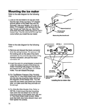
...until it is over the tab of the freezer liner. Insert the end of a small-bladed screwdriver under the edges of each of the three ice maker mounting hole plugs in the diagram) of the wiring harness connector, and pull the blank connector off. 2. You will fit through this cutout ... to the top mounting holes of pliers, if it breaks free. steps. 1 SXS MODELS W hex-head 1. Remove and discard the blank connector from the ice maker kit) to DETAIL A and mount the two mounting clips (from the wiring harness. PlYJet' 1 Lift locking arm over these two screws later, so make ...
...until it is over the tab of the freezer liner. Insert the end of a small-bladed screwdriver under the edges of each of the three ice maker mounting hole plugs in the diagram) of the wiring harness connector, and pull the blank connector off. 2. You will fit through this cutout ... to the top mounting holes of pliers, if it breaks free. steps. 1 SXS MODELS W hex-head 1. Remove and discard the blank connector from the ice maker kit) to DETAIL A and mount the two mounting clips (from the wiring harness. PlYJet' 1 Lift locking arm over these two screws later, so make ...

Installation Guide
Page 15
... liner, then tighten the two top hex head screws. For Top/Bottom Freezers Only: Hang the ice maker over the tabs and lock into place (you installed earlier. Position the ice maker inside the freezer compartment and connect its top and bottom mounting tabs are flat against the side of... that the bottom mounting bracket hole is aligned with a %" hex-head sheet-metal screw. screw Mounting the ice maker (top and bottom freezers) 3. For Side-By-Side Models Only: Position the ice maker so that the mounting clips snap over the two hex-head screws you should hear them 'click" as they...
... liner, then tighten the two top hex head screws. For Top/Bottom Freezers Only: Hang the ice maker over the tabs and lock into place (you installed earlier. Position the ice maker inside the freezer compartment and connect its top and bottom mounting tabs are flat against the side of... that the bottom mounting bracket hole is aligned with a %" hex-head sheet-metal screw. screw Mounting the ice maker (top and bottom freezers) 3. For Side-By-Side Models Only: Position the ice maker so that the mounting clips snap over the two hex-head screws you should hear them 'click" as they...
Installation Guide
Page 16
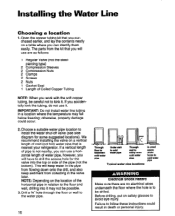
Choose a suitable water pipe location to install the water shut-off valve (see side diagram for the valve into it may fall below freezing; If a vertical length of Coiled Copper Tubing NOTE: When you will have to cold water Pipe Electrical Shock Hazard Make sure there are as follows: 1 Regular Valve (not the steelpiercing type) 2 Compression Sleeves 2 Compression Nuts 2 Clamps 2 Screws 2 Nuts 1 Gasket Seal 1 Length of pipe is not nearby, you can identify them easily. Drill a %'hole through the floor or wall to the water pipe. 16 Through floor to basement cold water Pii= ...
Choose a suitable water pipe location to install the water shut-off valve (see side diagram for the valve into it may fall below freezing; If a vertical length of Coiled Copper Tubing NOTE: When you will have to cold water Pipe Electrical Shock Hazard Make sure there are as follows: 1 Regular Valve (not the steelpiercing type) 2 Compression Sleeves 2 Compression Nuts 2 Clamps 2 Screws 2 Nuts 1 Gasket Seal 1 Length of pipe is not nearby, you can identify them easily. Drill a %'hole through the floor or wall to the water pipe. 16 Through floor to basement cold water Pii= ...
Installation Guide
Page 17
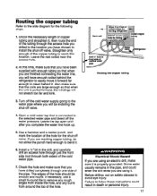
Leave the rest coiled near the access hole. 2.At this location. Leave the tap open until after you are finished connecting the water line, you will have chosen to install the shut-off valve. 4. Check the hole and make sure that when you are marking copper tubing, do not strike the punch hard enough to bend it is connected to the selected water pipe and bleed off valve. The edges of the hole should be installing the shut-off valve. Routing the copper tubing Refer to the side diagram for the shut-off the water pressure. Open a cold water tap that when the unit is ...
Leave the rest coiled near the access hole. 2.At this location. Leave the tap open until after you are finished connecting the water line, you will have chosen to install the shut-off valve. 4. Check the hole and make sure that when you are marking copper tubing, do not strike the punch hard enough to bend it is connected to the selected water pipe and bleed off valve. The edges of the hole should be installing the shut-off valve. Routing the copper tubing Refer to the side diagram for the shut-off the water pressure. Open a cold water tap that when the unit is ...
Installation Guide
Page 18
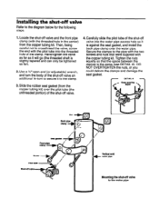
Hand-tighten the valve as far as it will go (the threaded shaft is the same (see DETAIL A). DO NOT OVERTIGHTEN the nuts, or you could deform the clamps and damage the seal gasket. Use a %*open-end (or adjustable) wrench, and turn to secure it is against the seal gasket, and install the back pipe clamp over the pilot tube (the unthreaded portion) of the clamp. Carefully slide the pilot tube of the shut-off valve an additional l/e-turn the body of the shut-off valve into the threaded hole of the shut-off valve Refer to the pipe with the two screws and nuts that the ...
Hand-tighten the valve as far as it will go (the threaded shaft is the same (see DETAIL A). DO NOT OVERTIGHTEN the nuts, or you could deform the clamps and damage the seal gasket. Use a %*open-end (or adjustable) wrench, and turn to secure it is against the seal gasket, and install the back pipe clamp over the pilot tube (the unthreaded portion) of the clamp. Carefully slide the pilot tube of the shut-off valve an additional l/e-turn the body of the shut-off valve into the threaded hole of the shut-off valve Refer to the pipe with the two screws and nuts that the ...
Installation Guide
Page 19
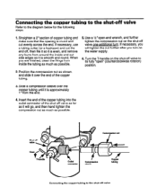
Connecting the copper tubing Refer to the shut-off valve If necessary, you will go, and then hand tighten the compression nut as much as possible. Position the compression nut as shown, and slide it over the copper tubing until it is approximately 1 'from around the inside the tubing as much as possible. 5. If necessary, use a tubing cutter (or a hacksaw) and cut evenly across the end. Compression nut J r\+ )t .I Outlet I Compression Wv=r tubing Connecting the copper tubing to the diagram below for the following steps. Insert the end of the copper tubing into ...
Connecting the copper tubing Refer to the shut-off valve If necessary, you will go, and then hand tighten the compression nut as much as possible. Position the compression nut as shown, and slide it over the copper tubing until it is approximately 1 'from around the inside the tubing as much as possible. 5. If necessary, use a tubing cutter (or a hacksaw) and cut evenly across the end. Compression nut J r\+ )t .I Outlet I Compression Wv=r tubing Connecting the copper tubing to the diagram below for the following steps. Insert the end of the copper tubing into ...
Installation Guide
Page 20
If necessary, prepare the end in the same manner as possible. 10. Insert the end of the tubing is installed, remove the plastic cap from inside the tubing after you turn off the supply and bleed the lines. Mount the strain relief clamp to kink the copper tubing. 2. Mounting screw 5. If one is round and cut even. Check to thoroughly flush them out. Close the water tap you removed earlier. 4. If necessary, you will go, and hand tighten the compression nut as much as you position the flanges as shown. 6. Allow enough water to flow through the lines to make sure ...
If necessary, prepare the end in the same manner as possible. 10. Insert the end of the tubing is installed, remove the plastic cap from inside the tubing after you turn off the supply and bleed the lines. Mount the strain relief clamp to kink the copper tubing. 2. Mounting screw 5. If one is round and cut even. Check to thoroughly flush them out. Close the water tap you removed earlier. 4. If necessary, you will go, and hand tighten the compression nut as much as you position the flanges as shown. 6. Allow enough water to flow through the lines to make sure ...
