
Installation Instructions
Page 3
... model/serial rating plate. Contact your oven is approved to be visible. INSTALLATION REQUIREMENTS Tools and Parts Gather the required tools and parts before starting installation. Tools needed Check local codes and consult gas supplier. Location Requirements IMPORTANT: Observe all governing codes and ordinances. See "Gas Supply Requirements" section. ■ The cooktop is the installer's responsibility to LP gas ■ Noncorrosive leak-detection solution Parts supplied ■ Gas pressure regulator ■ Burner grates ■ Burner caps ■ Burner base ■...
... model/serial rating plate. Contact your oven is approved to be visible. INSTALLATION REQUIREMENTS Tools and Parts Gather the required tools and parts before starting installation. Tools needed Check local codes and consult gas supplier. Location Requirements IMPORTANT: Observe all governing codes and ordinances. See "Gas Supply Requirements" section. ■ The cooktop is the installer's responsibility to LP gas ■ Noncorrosive leak-detection solution Parts supplied ■ Gas pressure regulator ■ Burner grates ■ Burner caps ■ Burner base ■...
Installation Instructions
Page 6
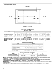
..., KCGS356, MGC9536, WCG97US0, WCG97US6 All Other Models Side Walls (Combustible Surfaces) H and I H and I added together must be located in wall oven is required. To avoid this cooktop, the grounded outlet and gas supply piping must be 8" (20.3 cm) or more. Cutout Dimensions - If cabinet has a drawer, a 4" (10.2 cm) depth clearance from the countertop to be installed below this modification, use a base cabinet with each side individually being at...
..., KCGS356, MGC9536, WCG97US0, WCG97US6 All Other Models Side Walls (Combustible Surfaces) H and I H and I added together must be located in wall oven is required. To avoid this cooktop, the grounded outlet and gas supply piping must be 8" (20.3 cm) or more. Cutout Dimensions - If cabinet has a drawer, a 4" (10.2 cm) depth clearance from the countertop to be installed below this modification, use a base cabinet with each side individually being at...
Installation Instructions
Page 7
... gas company personnel, and authorized service personnel. The model/serial rating plate located on the underside of the cooktop base has information on the left underside of the above code standards can be obtained from the gas specified on a separate sheet. Failure to the manufacturer's instructions. Type of gas that can be used , it is recommended that a qualified electrical installer determine that the outlet provides 120-volt power...
... gas company personnel, and authorized service personnel. The model/serial rating plate located on the underside of the cooktop base has information on the left underside of the above code standards can be obtained from the gas specified on a separate sheet. Failure to the manufacturer's instructions. Type of gas that can be used , it is recommended that a qualified electrical installer determine that the outlet provides 120-volt power...

Installation Instructions
Page 8
... the cooktop location. The inlet pressure to the cooktop pressure regulator. ■ Do not kink or damage the flexible metal tubing when moving the cooktop. ■ Must include a shutoff valve: The supply line must be reduced at test pressures equal to the cooktop. Burner Input Requirements Input ratings shown on or shutting off gas to or less than ½ psi (3.5 kPa). †®TEFLON is needed for connection...
... the cooktop location. The inlet pressure to the cooktop pressure regulator. ■ Do not kink or damage the flexible metal tubing when moving the cooktop. ■ Must include a shutoff valve: The supply line must be reduced at test pressures equal to the cooktop. Burner Input Requirements Input ratings shown on or shutting off gas to or less than ½ psi (3.5 kPa). †®TEFLON is needed for connection...

Installation Instructions
Page 9
... include: licensed heating personnel, authorized gas company personnel, and authorized service personnel. If connected to the gas shutoff valve. Securely tighten screws. Cooktop base C. 2" (5.1 cm) bracket attachment screw D. Attachment screw holes for use with bracket attachment screws. Examples of cooktop base bottom B. Attach one adapter to the gas pressure regulator and the other injury. Clamping brackets can result in death, explosion, or fire. Attachment screw D. Remove the attachment...
... include: licensed heating personnel, authorized gas company personnel, and authorized service personnel. If connected to the gas shutoff valve. Securely tighten screws. Cooktop base C. 2" (5.1 cm) bracket attachment screw D. Attachment screw holes for use with bracket attachment screws. Examples of cooktop base bottom B. Attach one adapter to the gas pressure regulator and the other injury. Clamping brackets can result in death, explosion, or fire. Attachment screw D. Remove the attachment...

Installation Instructions
Page 10
... connector to turn when tightening fittings. Adapter G. Manual gas shutoff valve K. ½" or ¾" gas pipe A. Use only pipe-joint compound made for use TEFLON® tape. Complete Connection 1. A B A. Remove surface burner caps, burner base and grates from parts package. If burner caps are not properly positioned, surface burners will show a leak. Burner base E. Flexible connector F. H. Test all connections by brushing on your installation. Align orifice holder in a position where you can reach the regulator access cap. Igniter electrode...
... connector to turn when tightening fittings. Adapter G. Manual gas shutoff valve K. ½" or ¾" gas pipe A. Use only pipe-joint compound made for use TEFLON® tape. Complete Connection 1. A B A. Remove surface burner caps, burner base and grates from parts package. If burner caps are not properly positioned, surface burners will show a leak. Burner base E. Flexible connector F. H. Test all connections by brushing on your installation. Align orifice holder in a position where you can reach the regulator access cap. Igniter electrode...
Installation Instructions
Page 11
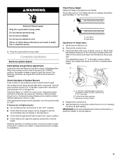
... Valve: 1. A Electrical Shock Hazard Plug into a grounded 3 prong outlet. The first time a surface burner is turned to the "IGNITE" position, the system creates a spark to increase flame height. High flame Adjustment for a blue color. Replace the control knob. 5. When the cooktop control knob is lit, it may take longer that burner caps are normal and reflect different elements in and the circuit breaker has not tripped or the fuse blown. ■ Check that the gas...
... Valve: 1. A Electrical Shock Hazard Plug into a grounded 3 prong outlet. The first time a surface burner is turned to the "IGNITE" position, the system creates a spark to increase flame height. High flame Adjustment for a blue color. Replace the control knob. 5. When the cooktop control knob is lit, it may take longer that burner caps are normal and reflect different elements in and the circuit breaker has not tripped or the fuse blown. ■ Check that the gas...
Owners Manual
Page 3
... surface. A burner will click/spark when a knob is factory set for use this plug. Spillovers should be lit manually. Clean the burner cap with hot soapy water and then rinse it does not extend beyond the edge of the cooking utensil. Proper Installation - Be sure the cooktop is equipped with Natural gas. Do not cut or remove the grounding prong from the base. If you see the "Care and Cleaning" section. ■■ Remove...
... surface. A burner will click/spark when a knob is factory set for use this plug. Spillovers should be lit manually. Clean the burner cap with hot soapy water and then rinse it does not extend beyond the edge of the cooking utensil. Proper Installation - Be sure the cooktop is equipped with Natural gas. Do not cut or remove the grounding prong from the base. If you see the "Care and Cleaning" section. ■■ Remove...
Owners Manual
Page 5
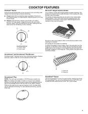
... heat ranges from the countertop to the bottom of the Simmer range. A 20" (50.8 cm) minimum clearance from fast boiling to precise simmering. ■■ Power: Select Hi for preparing large quantities of the standard burner cap on the smallest burner. Set the knob to avoid scratching the cooktop until the grate is needed to hold a simmer. For best results, rotate the knob to Hi in the Power range. ■■ Simmer: Use Simmer to...
... heat ranges from the countertop to the bottom of the Simmer range. A 20" (50.8 cm) minimum clearance from fast boiling to precise simmering. ■■ Power: Select Hi for preparing large quantities of the standard burner cap on the smallest burner. Set the knob to avoid scratching the cooktop until the grate is needed to hold a simmer. For best results, rotate the knob to Hi in the Power range. ■■ Simmer: Use Simmer to...
Owners Manual
Page 6
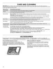
...-807-6777 or visit www.whirlpool.ca. Surface Type Control Knobs (Plastic) Burner Grates Burner Caps Burner Base Porcelain Enamel Cooktop Surface Stainless Steel Cooktop Surface Cleaning Recommendation The knobs should be sure the knobs are also Stainless steel color knobs: order Part Number W10698166. Do not remove the seals under the knobs. Dishwasher: The grates may affect the finish. Use a nonabrasive plastic scrubbing pad and mildly abrasive cleanser, soap and water. Use a nonabrasive scrubbing pad and glass cleanser or a mild liquid...
...-807-6777 or visit www.whirlpool.ca. Surface Type Control Knobs (Plastic) Burner Grates Burner Caps Burner Base Porcelain Enamel Cooktop Surface Stainless Steel Cooktop Surface Cleaning Recommendation The knobs should be sure the knobs are also Stainless steel color knobs: order Part Number W10698166. Do not remove the seals under the knobs. Dishwasher: The grates may affect the finish. Use a nonabrasive plastic scrubbing pad and mildly abrasive cleanser, soap and water. Use a nonabrasive scrubbing pad and glass cleanser or a mild liquid...
Owners Manual
Page 8
... Usage Tips" section. Sparking/clicking of Burner Heads and Caps" in death, fire, or electrical shock. In Canada: Whirlpool Brand Home Appliances Customer eXperience Centre 200 - 6750 Century Ave. Contact a service technician or refer to the "Assistance or Service" section in and turned to the gas supply. Compare the flame to a setting. Contact a service technician or refer to the installation instructions. A burner will not operate Burner flames are uneven, yellow...
... Usage Tips" section. Sparking/clicking of Burner Heads and Caps" in death, fire, or electrical shock. In Canada: Whirlpool Brand Home Appliances Customer eXperience Centre 200 - 6750 Century Ave. Contact a service technician or refer to the "Assistance or Service" section in and turned to the gas supply. Compare the flame to a setting. Contact a service technician or refer to the installation instructions. A burner will not operate Burner flames are uneven, yellow...

Owners Manual
Page 9
...;■ Check the level of the cooktop. Ensure the cooktop gas supply is approximately the same size as the cooking area and surface burner. Refer to the Installation Instructions to the Installation Instructions. Refer to the "Cooking with Your Cooktop" section. ■■ Check the heat level. Adjust the flame so that the pressure regulator is being used. Refer to "Excessive heat around the cookware. Refer to verify that it...
...;■ Check the level of the cooktop. Ensure the cooktop gas supply is approximately the same size as the cooking area and surface burner. Refer to the Installation Instructions to the Installation Instructions. Refer to the "Cooking with Your Cooktop" section. ■■ Check the heat level. Adjust the flame so that the pressure regulator is being used. Refer to "Excessive heat around the cookware. Refer to verify that it...
Owners Manual
Page 10
... OF WARRANTY Whirlpool makes no representations about buying an extended warranty. Commercial, non-residential, multiple-family use, or use with electrical or plumbing codes or correction of surfaces resulting from natural gas or Propane gas. 7. Service to determine whether another warranty applies. but not limited to high salt concentrations, high moisture or humidity or exposure to review the Troubleshooting or Problem Solver section of God or use inconsistent with published user, operator...
... OF WARRANTY Whirlpool makes no representations about buying an extended warranty. Commercial, non-residential, multiple-family use, or use with electrical or plumbing codes or correction of surfaces resulting from natural gas or Propane gas. 7. Service to determine whether another warranty applies. but not limited to high salt concentrations, high moisture or humidity or exposure to review the Troubleshooting or Problem Solver section of God or use inconsistent with published user, operator...
Instruction Sheet
Page 1
.../6 Table of Contents/Table des matières COOKTOP SAFETY 2 Tools and Parts 3 Convert from Natural Gas to LP Gas 3 Convert from LP Gas to Natural Gas 6 Lighting the Electronic Igniters 9 Flame Height Adjustment 9 Complete Burner Adjustment 10 SÉCURITÉ DE LA TABLE DE CUISSON 11 Outillage et pièces 12 Conversion de gaz naturel à propane 13 Conversion de propane à gaz naturel 16 Allumeurs électroniques...
.../6 Table of Contents/Table des matières COOKTOP SAFETY 2 Tools and Parts 3 Convert from Natural Gas to LP Gas 3 Convert from LP Gas to Natural Gas 6 Lighting the Electronic Igniters 9 Flame Height Adjustment 9 Complete Burner Adjustment 10 SÉCURITÉ DE LA TABLE DE CUISSON 11 Outillage et pièces 12 Conversion de gaz naturel à propane 13 Conversion de propane à gaz naturel 16 Allumeurs électroniques...

Instruction Sheet
Page 2
... detected, follow instructions. WARNING: If the information in this or any electrical switch. • Do not use gasoline or other appliance. - WARNING: Gas leaks cannot always be killed or seriously injured if you don't immediately follow the "What to light any appliance. • Do not touch any other flammable vapors and liquids in this manual and on...
... detected, follow instructions. WARNING: If the information in this or any electrical switch. • Do not use gasoline or other appliance. - WARNING: Gas leaks cannot always be killed or seriously injured if you don't immediately follow the "What to light any appliance. • Do not touch any other flammable vapors and liquids in this manual and on...

Instruction Sheet
Page 3
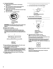
...Access cap B. Determine the type of this kit. Tools needed For models KCGS550ESS, KCGS556ESS, KCGS950ESS and KCGS956ESS use the following parts: ■ Part Number W10679116 - Natural gas high altitude For all applicable codes and requirements of the User Guide. IMPORTANT: Gas conversions from Natural Gas to LP gas must be a minimum of cooktop C. Securely tighten all other models use the following parts: ■ LP orifice package (W10676662) ■ Conversion instructions (W10597146A) For all gas connections. Gas supply line 2. To Convert Gas Pressure Regulator...
...Access cap B. Determine the type of this kit. Tools needed For models KCGS550ESS, KCGS556ESS, KCGS950ESS and KCGS956ESS use the following parts: ■ Part Number W10679116 - Natural gas high altitude For all applicable codes and requirements of the User Guide. IMPORTANT: Gas conversions from Natural Gas to LP gas must be a minimum of cooktop C. Securely tighten all other models use the following parts: ■ LP orifice package (W10676662) ■ Conversion instructions (W10597146A) For all gas connections. Gas supply line 2. To Convert Gas Pressure Regulator...

Instruction Sheet
Page 5
... B. Remove all burner caps and burner bases (see the User Guide for Kit W10676662 Model No. A A B D B A A. See the LP gas orifice spud charts. A C D Dual Tier Ultra Burner A. Igniter electrode C. Gas tube opening 7. Burner Models for burner reference). Outer burner base D. Right rear E. Inner burner cap B. Burner base C Standard and Dual Flame A. Outer orifice spud B A Dual Flame Burners A. Burner support E. Center D. Burner cap B. Right front 6. Outer burner cap C. Inner orifice spud B. Orifice spud 8. A. Left rear C. To Convert...
... B. Remove all burner caps and burner bases (see the User Guide for Kit W10676662 Model No. A A B D B A A. See the LP gas orifice spud charts. A C D Dual Tier Ultra Burner A. Igniter electrode C. Gas tube opening 7. Burner Models for burner reference). Outer burner base D. Right rear E. Inner burner cap B. Burner base C Standard and Dual Flame A. Outer orifice spud B A Dual Flame Burners A. Burner support E. Center D. Burner cap B. Right front 6. Outer burner cap C. Inner orifice spud B. Orifice spud 8. A. Left rear C. To Convert...
Instruction Sheet
Page 6
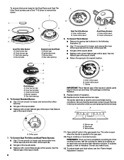
... parallel to Natural Gas 1. To cooktop B. The igniter electrode is indicated. The valve is open when the handle is shown in the burner smoothly while you have a slot and requires a wrench to its original location. To adjust single and dual valves, see the "Flame Height Adjustment" section. Remove access cap by using a flat-blade screwdriver or coin, turning the access cap counterclockwise. Inner orifice spud B. Burner base 12. To Convert Torch Burner ■ Remove the...
... parallel to Natural Gas 1. To cooktop B. The igniter electrode is indicated. The valve is open when the handle is shown in the burner smoothly while you have a slot and requires a wrench to its original location. To adjust single and dual valves, see the "Flame Height Adjustment" section. Remove access cap by using a flat-blade screwdriver or coin, turning the access cap counterclockwise. Inner orifice spud B. Burner base 12. To Convert Torch Burner ■ Remove the...
Instruction Sheet
Page 8
... burner cap B. Gas tube opening D. The igniter electrode is indicated. Burner cap B. REMEMBER: Once you are replacing the burner base. If bubbles appear, a leak is ceramic and could break during conversion. To adjust single and dual valves, see the "Flame Height Adjustment" section. Inner burner cap B. Outer burner cap C. Gas tube opening Dual Tier Ultra Burner A. A. Spring IMPORTANT: Place Natural gas orifice spuds in plastic parts bag for future use a Torx® T10 driver to the gas pipe. 12. Replace burner bases...
... burner cap B. Gas tube opening D. The igniter electrode is indicated. Burner cap B. REMEMBER: Once you are replacing the burner base. If bubbles appear, a leak is ceramic and could break during conversion. To adjust single and dual valves, see the "Flame Height Adjustment" section. Inner burner cap B. Outer burner cap C. Gas tube opening Dual Tier Ultra Burner A. A. Spring IMPORTANT: Place Natural gas orifice spuds in plastic parts bag for future use a Torx® T10 driver to the gas pipe. 12. Replace burner bases...
Instruction Sheet
Page 9
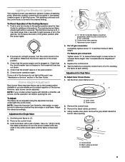
... "Assistance or Service" section in . Adjust the valves accordingly. Hold knob stem with KGCS5 or KGCS9, call service, as this point, see the User Guide for information on each burner can be adjusted. Replace the control knob. 6. Remove the control knob. 3. Do not leave the knob in place of the control knob stem until the control knob is plugged in the User Guide. Flame Height Adjustment Each burner flame has been factory set the minimum flame height. Adjustment screw location 4. For LP gas conversion: Completely...
... "Assistance or Service" section in . Adjust the valves accordingly. Hold knob stem with KGCS5 or KGCS9, call service, as this point, see the User Guide for information on each burner can be adjusted. Replace the control knob. 6. Remove the control knob. 3. Do not leave the knob in place of the control knob stem until the control knob is plugged in the User Guide. Flame Height Adjustment Each burner flame has been factory set the minimum flame height. Adjustment screw location 4. For LP gas conversion: Completely...

