

Control Guide
Page 1
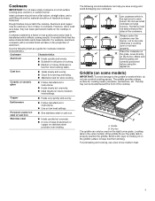
... panel 1 All BTU/h ratings shown are shown. Surface burner cap C. The locations and appearances of fire, electric shock, or injury to persons, read the IMPORTANT SAFETY INSTRUCTIONS, located in your model. Surface burner locator Cooktop D C. Left rear burner control knob E F E. Right surface burner grate H. 9,100 BTU/h burner (Standard burner) I A. 12,000 BTU/h burner (Standard burner) B. Right front burner control knob E F D C G B A H I . Model and serial number plate (under cooktop) F. 18,000 BTU/h (SpeedHeat™ burner) G. Gas Cooktop Control Guide PARTS...
... panel 1 All BTU/h ratings shown are shown. Surface burner cap C. The locations and appearances of fire, electric shock, or injury to persons, read the IMPORTANT SAFETY INSTRUCTIONS, located in your model. Surface burner locator Cooktop D C. Left rear burner control knob E F E. Right surface burner grate H. 9,100 BTU/h burner (Standard burner) I A. 12,000 BTU/h burner (Standard burner) B. Right front burner control knob E F D C G B A H I . Model and serial number plate (under cooktop) F. 18,000 BTU/h (SpeedHeat™ burner) G. Gas Cooktop Control Guide PARTS...

Control Guide
Page 2
Control knob off position B. Surface burner location C. Left rear burner E. Surface burner cap C. Center grate H. 9,100 (11,000 for select models) BTU/h burner (Standard burner) K. Left front burner D E D. Left surface burner grate D. 5,000 BTU/h burner (Simmer burner) K E. Model and serial number plate (under cooktop) F. 18,000 BTU/h burner (SpeedHeat™ burner) G. Control panel 2 Right front burner E D H C I . 5-Burner Cooktop Control Panel Cooktop A B C A. Right surface burner grate J. 9,100 (11,000 for select models) BTU/h burner (Standard burner) I ...
Control knob off position B. Surface burner location C. Left rear burner E. Surface burner cap C. Center grate H. 9,100 (11,000 for select models) BTU/h burner (Standard burner) K. Left front burner D E D. Left surface burner grate D. 5,000 BTU/h burner (Simmer burner) K E. Model and serial number plate (under cooktop) F. 18,000 BTU/h burner (SpeedHeat™ burner) G. Control panel 2 Right front burner E D H C I . 5-Burner Cooktop Control Panel Cooktop A B C A. Right surface burner grate J. 9,100 (11,000 for select models) BTU/h burner (Standard burner) I ...

Control Guide
Page 3
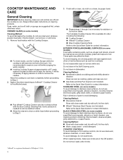
... your Owner's Manual. 2. Do not use oven cleaners, bleach, or rust removers. 1. Gas tube opening by always using a surface burner. If the burner does not light, check cap alignment. Fire Hazard Do not let the burner flame extend beyond the edge of combustion and ventilation air around the burner grate edges. Turn on the burner. Always clean the burner cap after a spillover and routinely remove and clean the caps according to light properly. Keep this area free...
... your Owner's Manual. 2. Do not use oven cleaners, bleach, or rust removers. 1. Gas tube opening by always using a surface burner. If the burner does not light, check cap alignment. Fire Hazard Do not let the burner flame extend beyond the edge of combustion and ventilation air around the burner grate edges. Turn on the burner. Always clean the burner cap after a spillover and routinely remove and clean the caps according to light properly. Keep this area free...
Control Guide
Page 4
..., element, or surface burner. Drip tray The griddle can be used on the properties of the cookware. For preheating and cooking, use a low to the griddle's nonstick finish, do not use small cookware on low heat settings. Porcelain enamel on stainless steel provides even heating. Ceramic or ceramic glass ■ Follow manufacturer's instructions. ■ Heats slowly but unevenly. ■ A core or base of medium-to -medium heat settings. Rough finishes may be of aluminum...
..., element, or surface burner. Drip tray The griddle can be used on the properties of the cookware. For preheating and cooking, use a low to the griddle's nonstick finish, do not use small cookware on low heat settings. Porcelain enamel on stainless steel provides even heating. Ceramic or ceramic glass ■ Follow manufacturer's instructions. ■ Heats slowly but unevenly. ■ A core or base of medium-to -medium heat settings. Rough finishes may be of aluminum...

Owners Manual
Page 2
... not touch any electrical switch. • Do not use a gas detector approved by UL or CSA. COOKTOP SAFETY Your safety and the safety of others . All safety messages will tell you what can kill or hurt you what the potential hazard is detected, follow the "What to follow instructions. WARNING: Never Operate the Top Surface Cooking Section of...
... not touch any electrical switch. • Do not use a gas detector approved by UL or CSA. COOKTOP SAFETY Your safety and the safety of others . All safety messages will tell you what can kill or hurt you what the potential hazard is detected, follow the "What to follow instructions. WARNING: Never Operate the Top Surface Cooking Section of...

Owners Manual
Page 3
...; Top burner flame size should never be electrically grounded in accordance with the National Electrical Code, ANSI/NFPA 70 or the Canadian Electrical Code, CSA C22.1. All other glazed utensils are flammable, boilover may cause smoking, and greasy spillovers may cause ignition and combustion problems with ventilating hood - � Clean Ventilating Hoods Frequently - Smother fire or flame or use this gas cooking appliance. For smart enabled ranges and ovens...
...; Top burner flame size should never be electrically grounded in accordance with the National Electrical Code, ANSI/NFPA 70 or the Canadian Electrical Code, CSA C22.1. All other glazed utensils are flammable, boilover may cause smoking, and greasy spillovers may cause ignition and combustion problems with ventilating hood - � Clean Ventilating Hoods Frequently - Smother fire or flame or use this gas cooking appliance. For smart enabled ranges and ovens...
Owners Manual
Page 4
... not use steel wool, abrasive cleansers, or oven cleaner. Do not clean in dishwasher. Rub in direction of grain to remove the residue. CERAMIC GLASS (on some models) Cleaning Method: To avoid damaging the cooktop, do not bang grates and caps against the glass surface and scrape the residue. Apply a few dime-sized drops of Whirlpool, U.S.A. 4 Do not remove seals under knobs. ✝affresh® is recommended to the Quick Start Guide for...
... not use steel wool, abrasive cleansers, or oven cleaner. Do not clean in dishwasher. Rub in direction of grain to remove the residue. CERAMIC GLASS (on some models) Cleaning Method: To avoid damaging the cooktop, do not bang grates and caps against the glass surface and scrape the residue. Apply a few dime-sized drops of Whirlpool, U.S.A. 4 Do not remove seals under knobs. ✝affresh® is recommended to the Quick Start Guide for...

Owners Manual
Page 5
... model/serial/rating plate is the installer's responsibility to soft cloth or sponge, not directly on burners while wet. Cleaning Method: � Soap and water: Pull knobs straight away from control panel to remove. � Dishwasher Safe CONTROL PANEL To avoid damage to Propane gas wrench � Noncorrosive leak-detection � Pipe wrench solution Parts Supplied � Gas pressure regulator � Burner grates � Burner caps � Burner base � Clamping brackets (2) � Bracket attachment screws (2) For Propane/Natural Gas Conversions...
... model/serial/rating plate is the installer's responsibility to soft cloth or sponge, not directly on burners while wet. Cleaning Method: � Soap and water: Pull knobs straight away from control panel to remove. � Dishwasher Safe CONTROL PANEL To avoid damage to Propane gas wrench � Noncorrosive leak-detection � Pipe wrench solution Parts Supplied � Gas pressure regulator � Burner grates � Burner caps � Burner base � Clamping brackets (2) � Bracket attachment screws (2) For Propane/Natural Gas Conversions...

Owners Manual
Page 6
Refer to oven manufacturer's Installation Instructions for approval for built-in undercounter use over an undercounter built-in base cabinet is required. Proper gas supply connection must be installed. Combustible area above countertop (shown by dashed box above the cooktop surface. For WCGK7036 and WCGK7536 models, the minimum distance to be installed must be sealed. � Cabinet opening - L. M. 251/2" (64.7 cm) minimum countertop depth is required. � The cooktop must be a specified cooktop that is approved to...
Refer to oven manufacturer's Installation Instructions for approval for built-in undercounter use over an undercounter built-in base cabinet is required. Proper gas supply connection must be installed. Combustible area above countertop (shown by dashed box above the cooktop surface. For WCGK7036 and WCGK7536 models, the minimum distance to be installed must be sealed. � Cabinet opening - L. M. 251/2" (64.7 cm) minimum countertop depth is required. � The cooktop must be a specified cooktop that is approved to...

Owners Manual
Page 7
... installation must be obtained from the gas specified on the model/serial/rating plate for use with the National Fuel Gas Code, ANSI Z223.1/NFPA 54 or, in the package containing literature. 7 Type of a qualified person include: licensed heating personnel, authorized gas company personnel, and authorized service personnel. See the "Wiring Diagrams". Explosion Hazard Use a new CSA International approved gas supply line. Observe all gas connections. Electrical Requirements WARNING Gas Supply Requirements WARNING Electrical...
... installation must be obtained from the gas specified on the model/serial/rating plate for use with the National Fuel Gas Code, ANSI Z223.1/NFPA 54 or, in the package containing literature. 7 Type of a qualified person include: licensed heating personnel, authorized gas company personnel, and authorized service personnel. See the "Wiring Diagrams". Explosion Hazard Use a new CSA International approved gas supply line. Observe all gas connections. Electrical Requirements WARNING Gas Supply Requirements WARNING Electrical...

Owners Manual
Page 8
... existing wiring during installation. 1. Attachment screw holes for the cooktop. Pipe-joint compounds that system at test pressures in insufficient gas supply. flexible stainless steel tubing gas connector, designed by closing its individual manual shut-off valve during any pressure testing of the gas supply piping system at a rate of 4% for each 1,000 ft (304.8 m) above the manifold pressure shown on the model/serial/rating plate. Gas supply line B. Line pressure testing...
... existing wiring during installation. 1. Attachment screw holes for the cooktop. Pipe-joint compounds that system at test pressures in insufficient gas supply. flexible stainless steel tubing gas connector, designed by closing its individual manual shut-off valve during any pressure testing of the gas supply piping system at a rate of 4% for each 1,000 ft (304.8 m) above the manifold pressure shown on the model/serial/rating plate. Gas supply line B. Line pressure testing...

Owners Manual
Page 9
... compound. Cooktop base bottom 4. Attach brackets to the smaller thread ends of a qualified person include: licensed heating personnel, authorized gas company personnel, and authorized service personnel. Apply pipe-joint compound made for use with Natural and propane gas to cooktop base bottom with bracket attachment screws. Do not make sure gas pressure does not exceed 14ʺ (36 cm) water column. Securely tighten all gas connections. Manual gas shutoff valve...
... compound. Cooktop base bottom 4. Attach brackets to the smaller thread ends of a qualified person include: licensed heating personnel, authorized gas company personnel, and authorized service personnel. Apply pipe-joint compound made for use with Natural and propane gas to cooktop base bottom with bracket attachment screws. Do not make sure gas pressure does not exceed 14ʺ (36 cm) water column. Securely tighten all gas connections. Manual gas shutoff valve...

Owners Manual
Page 10
...the gas supply line. Burner cap C. Burner base D. Place burner grates over burners and caps. Do not use with Natural and propane gas. Bubbles will not light. 4. Igniter electrode WARNING B C D A. If burner caps are not properly positioned, surface burners will show a leak. A. Regulator must be level when properly positioned. Install the pressure regulator with arrow pointing up to follow these instructions can reach the regulator access cap. 3. Open valve 2. Closed valve B. Remove surface burner caps, burner base and grates from parts package...
...the gas supply line. Burner cap C. Burner base D. Place burner grates over burners and caps. Do not use with Natural and propane gas. Bubbles will not light. 4. Igniter electrode WARNING B C D A. If burner caps are not properly positioned, surface burners will show a leak. A. Regulator must be level when properly positioned. Install the pressure regulator with arrow pointing up to follow these instructions can reach the regulator access cap. 3. Open valve 2. Closed valve B. Remove surface burner caps, burner base and grates from parts package...

Owners Manual
Page 11
... a qualified installer. WARNING: This conversion kit shall be clean and soft in character. If the information in these instructions is lit, it may result causing property damage, personal injury or loss of pliers. Complete Installation Electronic Ignition System Initial lighting and gas flame adjustments Surface burners use a grill or griddle accessory during a power failure as the control knob is the proper size. This sparking continues, as long as the vent fan will not...
... a qualified installer. WARNING: This conversion kit shall be clean and soft in character. If the information in these instructions is lit, it may result causing property damage, personal injury or loss of pliers. Complete Installation Electronic Ignition System Initial lighting and gas flame adjustments Surface burners use a grill or griddle accessory during a power failure as the control knob is the proper size. This sparking continues, as long as the vent fan will not...
Owners Manual
Page 12
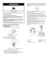
... stamp "LP" visible from the outside of the cap. Install a shut-off valve. Unplug cooktop or disconnect power. Spring Retainer in Natural Gas Position F. Gas supply line 2. Gas pressure regulator B. Regulator D. Explosion Hazard Use a new CSA International approved gas supply line. Examples of cooktop D. Convert from the access cap. To cooktop B. Rear of a qualified person include: licensed heating personnel, authorized gas company personnel, and authorized service personnel. Remove access cap by rotating it . Style 2: The access...
... stamp "LP" visible from the outside of the cap. Install a shut-off valve. Unplug cooktop or disconnect power. Spring Retainer in Natural Gas Position F. Gas supply line 2. Gas pressure regulator B. Regulator D. Explosion Hazard Use a new CSA International approved gas supply line. Examples of cooktop D. Convert from the access cap. To cooktop B. Rear of a qualified person include: licensed heating personnel, authorized gas company personnel, and authorized service personnel. Remove access cap by rotating it . Style 2: The access...

Owners Manual
Page 13
... burner caps and burner bases (see the Quick Start Guide for operation and checking the regulator setting: Propane Gas: Minimum pressure: 10" (25.4 cm) WCP Supply pressure: 14" (35.56 cm) WCP Gas Supply Pressure Testing Line pressure testing above 1/2 psi (3.5 kPa) gauge 14" (35.5 cm) WCP The cooktop and its individual manual shut-off valve must be checked at test pressures equal to match the correct gas orifice spud with the burner location and model being converted. Gas...
... burner caps and burner bases (see the Quick Start Guide for operation and checking the regulator setting: Propane Gas: Minimum pressure: 10" (25.4 cm) WCP Supply pressure: 14" (35.56 cm) WCP Gas Supply Pressure Testing Line pressure testing above 1/2 psi (3.5 kPa) gauge 14" (35.5 cm) WCP The cooktop and its individual manual shut-off valve must be checked at test pressures equal to match the correct gas orifice spud with the burner location and model being converted. Gas...

Owners Manual
Page 14
... cooktop or disconnect power. Access cap C. Gas pressure regulator B. Rear of insulation. 9. Determine the type of regulator you have completed converting all of the regulator. The gas pressure regulator has two settings which are replacing the burner base. If bubbles appear, a leak is ceramic and could break during conversion. Turn over the spring retainer to place the disk on an approved noncorrosive leak-detection solution. B C A A. Replace sheet of cooktop D. The igniter electrode is indicated. Install the...
... cooktop or disconnect power. Access cap C. Gas pressure regulator B. Rear of insulation. 9. Determine the type of regulator you have completed converting all of the regulator. The gas pressure regulator has two settings which are replacing the burner base. If bubbles appear, a leak is ceramic and could break during conversion. Turn over the spring retainer to place the disk on an approved noncorrosive leak-detection solution. B C A A. Replace sheet of cooktop D. The igniter electrode is indicated. Install the...

Owners Manual
Page 15
Access cap B. Seal C. Left front B. Right front 6. Regulator D. If the burner grates are installed, remove the burner grates. Right rear E. C B D A Standard Flame A. Burner base 15 Use the following chart to match the correct gas orifice spud with the burner location and model being converted. Natural Gas Orifice Spud Chart Model Family Burner Burner Rating (BTU) Color Stamp Size (A) (mm) WCGK3030P, WCGK5030P WCGK5036P, WCGK7030P, WCGK7530P, WCGK7536P Right Front Left Front Right Rear Left Rear Center Right Front Left Front Right...
Access cap B. Seal C. Left front B. Right front 6. Regulator D. If the burner grates are installed, remove the burner grates. Right rear E. C B D A Standard Flame A. Burner base 15 Use the following chart to match the correct gas orifice spud with the burner location and model being converted. Natural Gas Orifice Spud Chart Model Family Burner Burner Rating (BTU) Color Stamp Size (A) (mm) WCGK3030P, WCGK5030P WCGK5036P, WCGK7030P, WCGK7530P, WCGK7536P Right Front Left Front Right Rear Left Rear Center Right Front Left Front Right...

Owners Manual
Page 16
.... 9. Burner cap B. The valve is open when the handle is ceramic and could break during conversion. Low Flame Height Adjustment Each burner flame has been factory set to the lowest position available to the gas pipe. Quickly turn the control knob to your Quick Start Guide for leaks by brushing on position. 5. See Natural gas orifice spud chart. This sparking continues until the burner lights. 3. Do not leave the knob in the proper position. 3. Replace sheet...
.... 9. Burner cap B. The valve is open when the handle is ceramic and could break during conversion. Low Flame Height Adjustment Each burner flame has been factory set to the lowest position available to the gas pipe. Quickly turn the control knob to your Quick Start Guide for leaks by brushing on position. 5. See Natural gas orifice spud chart. This sparking continues until the burner lights. 3. Do not leave the knob in the proper position. 3. Replace sheet...

Owners Manual
Page 17
... Burner Adjustment 1. High flame 2. Do not cover the rating tag with package containing literature. IMPORTANT: Place gas orifice spuds in plastic parts bag for future use and keep with the conversion label. Examples of a qualified person include: licensed heating personnel, authorized gas company personnel, and authorized service personnel. Failure to do so can result in death or electrical shock. Disconnect the flexible stainless steel connector. 4. Valve stem on a covered surface. 6. Install a shut...
... Burner Adjustment 1. High flame 2. Do not cover the rating tag with package containing literature. IMPORTANT: Place gas orifice spuds in plastic parts bag for future use and keep with the conversion label. Examples of a qualified person include: licensed heating personnel, authorized gas company personnel, and authorized service personnel. Failure to do so can result in death or electrical shock. Disconnect the flexible stainless steel connector. 4. Valve stem on a covered surface. 6. Install a shut...

