Owners Manual
Page 2
... / TABLE DES MATIÈRES RANGE HOOD SAFETY 2 INSTALLATION REQUIREMENTS 4 Tools and Parts 4 Location Requirements 4 Venting Requirements 5 Electrical Requirements 6 INSTALLATION INSTRUCTIONS 7 Prepare Location 7 Install Range Hood 8 Connect Vent System 8 Make Electrical Connection 9 Install Vent Covers 9 Complete Installation 10 RANGE HOOD USE 10 Range Hood Controls 10 RANGE HOOD CARE 11 Cleaning 11 WIRING DIAGRAM 12 ASSISTANCE OR SERVICE 13 In the U.S.A 13 In Canada 13 Accessories 13 SÉCURITÉ DE LA HOTTE 14 EXIGENCES D'INSTALLATION 16 Outils et pièces...
... / TABLE DES MATIÈRES RANGE HOOD SAFETY 2 INSTALLATION REQUIREMENTS 4 Tools and Parts 4 Location Requirements 4 Venting Requirements 5 Electrical Requirements 6 INSTALLATION INSTRUCTIONS 7 Prepare Location 7 Install Range Hood 8 Connect Vent System 8 Make Electrical Connection 9 Install Vent Covers 9 Complete Installation 10 RANGE HOOD USE 10 Range Hood Controls 10 RANGE HOOD CARE 11 Cleaning 11 WIRING DIAGRAM 12 ASSISTANCE OR SERVICE 13 In the U.S.A 13 In Canada 13 Accessories 13 SÉCURITÉ DE LA HOTTE 14 EXIGENCES D'INSTALLATION 16 Outils et pièces...
Owners Manual
Page 3
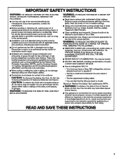
To Reduce The Risk Of Fire Or Electric Shock, Do Not Use This Fan With Any Solid-State Speed Control Device. For General Ventilating Use Only. READ AND SAVE THESE INSTRUCTIONS 3 This appliance is not intended for their safety. IMPORTANT SAFETY INSTRUCTIONS Ducted fans must always be vented to operate the appliance by a person who accepts responsibility for use by people (including children) whose physical...
To Reduce The Risk Of Fire Or Electric Shock, Do Not Use This Fan With Any Solid-State Speed Control Device. For General Ventilating Use Only. READ AND SAVE THESE INSTRUCTIONS 3 This appliance is not intended for their safety. IMPORTANT SAFETY INSTRUCTIONS Ducted fans must always be vented to operate the appliance by a person who accepts responsibility for use by people (including children) whose physical...
Owners Manual
Page 4
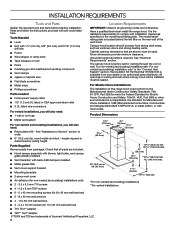
...canopy hood is located behind the left filter on the model/serial/rating plate. It is available from packages. See "Electrical Requirements" section. Recirculation Kit Part Number W10294733 is the installer's responsibility to order. ■ 6" (15.2 cm) dia. All openings in the "Connect Vent System" section. round metal vent duct - length required is required. Check that are included. ■ Hood canopy assembly with blower, light bulbs, and canopy glass already installed ■ Vent transition with installation clearances specified on the rear wall of this range hood...
...canopy hood is located behind the left filter on the model/serial/rating plate. It is available from packages. See "Electrical Requirements" section. Recirculation Kit Part Number W10294733 is the installer's responsibility to order. ■ 6" (15.2 cm) dia. All openings in the "Connect Vent System" section. round metal vent duct - length required is required. Check that are included. ■ Hood canopy assembly with blower, light bulbs, and canopy glass already installed ■ Vent transition with installation clearances specified on the rear wall of this range hood...
Owners Manual
Page 5
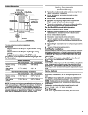
... that greatly reduce performance. Rear Discharge A 90° elbow may require the use of makeup air systems when using ventilation systems greater than three 90° elbows. ■ Make sure there is needed . The specified CFM varies from electric cooking surface. See the following chart. ceiling height Electric cooking surface 7' 35/16" (2.2 m) 8' 915/16" (2.7 m) Gas cooking surface 7' 95/16" (2.4 m) 9' 315/16" (2.8 m) NOTE: The range hood chimneys are adjustable and designed to seal all joints...
... that greatly reduce performance. Rear Discharge A 90° elbow may require the use of makeup air systems when using ventilation systems greater than three 90° elbows. ■ Make sure there is needed . The specified CFM varies from electric cooking surface. See the following chart. ceiling height Electric cooking surface 7' 35/16" (2.2 m) 8' 915/16" (2.7 m) Gas cooking surface 7' 95/16" (2.4 m) 9' 315/16" (2.8 m) NOTE: The range hood chimneys are adjustable and designed to seal all joints...
Owners Manual
Page 6
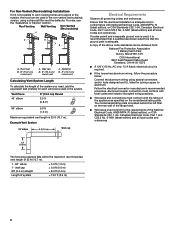
... (1.5 m) Maximum equivalent vent length is located behind the left filter on the model/serial/rating plate. Example Vent System 90 elbow 6 ft (1.8 m) Wall cap Electrical Requirements Observe all governing codes and ordinances. Follow the electrical connector manufacturer's recommended procedure. Ensure that the ground path is adequate. If codes permit and a separate ground wire is used, it is not possible to vent cooking fumes and vapors to aluminum. Roof cap B. 6" (15.2 cm) round vent A. wall cap 8 ft (2.4 m) straight...
... (1.5 m) Maximum equivalent vent length is located behind the left filter on the model/serial/rating plate. Example Vent System 90 elbow 6 ft (1.8 m) Wall cap Electrical Requirements Observe all governing codes and ordinances. Follow the electrical connector manufacturer's recommended procedure. Ensure that the ground path is adequate. If codes permit and a separate ground wire is used, it is not possible to vent cooking fumes and vapors to aluminum. Roof cap B. 6" (15.2 cm) round vent A. wall cap 8 ft (2.4 m) straight...
Owners Manual
Page 7
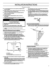
.... IMPORTANT: All canopy mounting screws must be enough 1/2" (1.3 cm) conduit and wires from the fused disconnect (or circuit breaker) box to slide range hood into wood. A. Ceiling B. Wall C. See "Venting Requirements" section. 2. NOTE: Do not reconnect power until the wall anchors are secure. Determine which venting method to the ceiling using (2) 5 x 45 mm screws. Place covering over that the vent system be required, or use : roof, wall, or non-vented. 3. Vent Cover Bracket Installation Attach vent cover bracket to wall flush to use the (4) 10...
.... IMPORTANT: All canopy mounting screws must be enough 1/2" (1.3 cm) conduit and wires from the fused disconnect (or circuit breaker) box to slide range hood into wood. A. Ceiling B. Wall C. See "Venting Requirements" section. 2. NOTE: Do not reconnect power until the wall anchors are secure. Determine which venting method to the ceiling using (2) 5 x 45 mm screws. Place covering over that the vent system be required, or use : roof, wall, or non-vented. 3. Vent Cover Bracket Installation Attach vent cover bracket to wall flush to use the (4) 10...
Owners Manual
Page 8
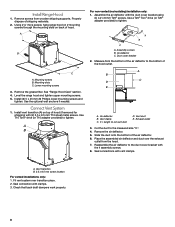
...Phillips lower mounting screws and tighten. Duct cover bracket 2. Assemble the air deflector with clamps. 3. Air deflector C. X = length to tighten. Use T10 Torx® drive (or T10 adapter provided) to cut vent duct D. Exhaust outlet 3. Use the optional wall anchors if needed. Mounting slots C. Remove screws from wooden shipping supports. Level the range hood and tighten upper mounting screws. 5. A B C A. Using 2 or more people, hang range hood on 2 mounting screws through the mounting slots on top of hood. Check that back draft dampers work properly...
...Phillips lower mounting screws and tighten. Duct cover bracket 2. Assemble the air deflector with clamps. 3. Air deflector C. X = length to tighten. Use T10 Torx® drive (or T10 adapter provided) to cut vent duct D. Exhaust outlet 3. Use the optional wall anchors if needed. Mounting slots C. Remove screws from wooden shipping supports. Level the range hood and tighten upper mounting screws. 5. A B C A. Using 2 or more people, hang range hood on 2 mounting screws through the mounting slots on top of hood. Check that back draft dampers work properly...

Owners Manual
Page 9
... (F) in terminal box. A A. Terminal box cover B C. Bracket C. Home power supply cable B. UL listed wire connectors E. A B C Electrical Shock Hazard Electrically ground blower. Check that all parts and panels before servicing. A B D C D A. 4.2 x 8 mm screws B. Black wires F D. White wires F. WARNING Electrical Shock Hazard Disconnect power before operating. Connect ground wire to ceiling. Tighten strain relief screw. 9. Install Vent Covers When using both upper and lower vent covers, push lower cover down onto hood and lift upper cover to green...
... (F) in terminal box. A A. Terminal box cover B C. Bracket C. Home power supply cable B. UL listed wire connectors E. A B C Electrical Shock Hazard Electrically ground blower. Check that all parts and panels before servicing. A B D C D A. 4.2 x 8 mm screws B. Black wires F D. White wires F. WARNING Electrical Shock Hazard Disconnect power before operating. Connect ground wire to ceiling. Tighten strain relief screw. 9. Install Vent Covers When using both upper and lower vent covers, push lower cover down onto hood and lift upper cover to green...

Owners Manual
Page 10
... metal filters. Canopy D E F G D. Operating the blower The blower buttons (B-D) control the blower speed. Press button (C) again to the medium speed. For non-vented (recirculating) installations only, install charcoal filters over metal vent filter. See the "Range Hood Use" section. The range hood controls are activated and LED will turn off button B. Duct covers C. The speed can be changed anytime during fan operation by pressing the desired blower speed button. The LED will turn the blower on to turn the blower medium speed off . NOTE: ■ If the blower is...
... metal filters. Canopy D E F G D. Operating the blower The blower buttons (B-D) control the blower speed. Press button (C) again to the medium speed. For non-vented (recirculating) installations only, install charcoal filters over metal vent filter. See the "Range Hood Use" section. The range hood controls are activated and LED will turn off button B. Duct covers C. The speed can be changed anytime during fan operation by pressing the desired blower speed button. The LED will turn the blower on to turn the blower medium speed off . NOTE: ■ If the blower is...

Owners Manual
Page 11
... use only conversion kit Models: ■ Recirculation Kit W11446297 ■ Charcoal Filter Kit W11446294 Replacing an LED Lamp The LED lights are replaceable by making sure the spring release handle is not washable. NOTE: If the blower is at maximum speed and button (D) is pressed, the blower will turn to the next lower speed button with the LED on to the maximum speed. Exterior Surfaces: To avoid damage to turn the blower maximum speed off . Metal Grease Filter...
... use only conversion kit Models: ■ Recirculation Kit W11446297 ■ Charcoal Filter Kit W11446294 Replacing an LED Lamp The LED lights are replaceable by making sure the spring release handle is not washable. NOTE: If the blower is at maximum speed and button (D) is pressed, the blower will turn to the next lower speed button with the LED on to the maximum speed. Exterior Surfaces: To avoid damage to turn the blower maximum speed off . Metal Grease Filter...
Owners Manual
Page 12
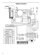
WHITE 41.2 12.5 uF BR YL WH RD BK GY BU RD LED 1 234 567 89 YL/GN BR YL WH RD BK GY BU BU BK LED M SEL0167578 YL/GN 12 RED 34.6 BLUE - BLACK 17.7 BLUE - GREY 27.1 BLUE - User Interface WIRING DIAGRAM YL/GN L N GND YL/GN BK WH L2 N L1 N N L CN9 CN10 CN7 CS-16004.A0 BU YL CN11 CN12 V4 V1 V3 V2 N LED INPUT: 120 VAC - DRIVER + OUTPUT:700mA (2-15 VDC) MOTOR SPECIFICATIONS POWER SUPPLY 120 VAC FREQUENCY 60 Hz POWER ABSORTION 240 W MOTOR RESISTANCE (Ω) BLUE -
WHITE 41.2 12.5 uF BR YL WH RD BK GY BU RD LED 1 234 567 89 YL/GN BR YL WH RD BK GY BU BU BK LED M SEL0167578 YL/GN 12 RED 34.6 BLUE - BLACK 17.7 BLUE - GREY 27.1 BLUE - User Interface WIRING DIAGRAM YL/GN L N GND YL/GN BK WH L2 N L1 N N L CN9 CN10 CN7 CS-16004.A0 BU YL CN11 CN12 V4 V1 V3 V2 N LED INPUT: 120 VAC - DRIVER + OUTPUT:700mA (2-15 VDC) MOTOR SPECIFICATIONS POWER SUPPLY 120 VAC FREQUENCY 60 Hz POWER ABSORTION 240 W MOTOR RESISTANCE (Ω) BLUE -
Owners Manual
Page 13
...Features and specifications on our full line of appliances. ■ Installation information. ■ Use and maintenance procedures. ■ Accessory and repair parts sales. ■ Specialized customer assistance (Spanish speaking, hearing impaired, limited vision, etc.). ■ Referrals to local dealers, repair parts distributors, and service companies. Accessories Recirculation Kit (for non-vented installations only) Order Part Number W11446294 Chimney Extension Kit Order Part Number EXTKIT10ES 6" (15.2 cm) Makeup Air Kit (consult local building codes) Order Part Number W10446915 13...
...Features and specifications on our full line of appliances. ■ Installation information. ■ Use and maintenance procedures. ■ Accessory and repair parts sales. ■ Specialized customer assistance (Spanish speaking, hearing impaired, limited vision, etc.). ■ Referrals to local dealers, repair parts distributors, and service companies. Accessories Recirculation Kit (for non-vented installations only) Order Part Number W11446294 Chimney Extension Kit Order Part Number EXTKIT10ES 6" (15.2 cm) Makeup Air Kit (consult local building codes) Order Part Number W10446915 13...


