
Owner's Manual
Page 5
... 14 Connecting a TV 15 Connecting a DVD player/recorder 16 Connecting a VCR 17 Connecting a digital satellite tuner or a cable TV tuner 18 Connecting other external components 19 Connecting a subwoofer 20 Connecting the power supply cable 21 SETUP GETTING STARTED 22 Installing batteries in the remote control ...timer 55 Canceling the sleep timer 56 ADVANCED OPERATION BASIC SETUP 57 MANUAL SETUP 63 Using MANUAL SETUP 64 BEAM MENU 65 SOUND MENU 69 INPUT MENU 71 DISPLAY MENU 73 ADJUSTING SYSTEM PARAMETERS ...........75 Setting the maximum volume level 75 Protecting the current ...
... 14 Connecting a TV 15 Connecting a DVD player/recorder 16 Connecting a VCR 17 Connecting a digital satellite tuner or a cable TV tuner 18 Connecting other external components 19 Connecting a subwoofer 20 Connecting the power supply cable 21 SETUP GETTING STARTED 22 Installing batteries in the remote control ...timer 55 Canceling the sleep timer 56 ADVANCED OPERATION BASIC SETUP 57 MANUAL SETUP 63 Using MANUAL SETUP 64 BEAM MENU 65 SOUND MENU 69 INPUT MENU 71 DISPLAY MENU 73 ADJUSTING SYSTEM PARAMETERS ...........75 Setting the maximum volume level 75 Protecting the current ...
Owner's Manual
Page 6
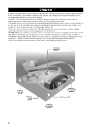
... listening position from its built-in subwoofers (2) and individual speakers (21). The YSP-800 projects sound beams containing surround sound information for the front right (R), front left (L), surround right (SR) and surround left speaker 2 YAMAHA YSP-800 Digital Sound Projector challenges this simple, yet stylish Digital Sound Projector. Sit back and enjoy the real sound experience of this preconception that complicated speaker setup and troublesome wiring go hand...
... listening position from its built-in subwoofers (2) and individual speakers (21). The YSP-800 projects sound beams containing surround sound information for the front right (R), front left (L), surround right (SR) and surround left speaker 2 YAMAHA YSP-800 Digital Sound Projector challenges this simple, yet stylish Digital Sound Projector. Sit back and enjoy the real sound experience of this preconception that complicated speaker setup and troublesome wiring go hand...
Owner's Manual
Page 7
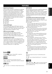
...YAMAHA Parametric Room Acoustic Optimizer (YPAO) technology with all the dramatic sound impact that the director intended to convey. "DTS", and "Neo:6" are trademarks of 1 Ltd. so that you can experience movies at home with the aid of the supplied optimizer microphone so that you can avoid troublesome listening-based speaker...of sound beams that best matches your video monitor. The ' ' logo and 'Digital Sound Projector™' are trademarks of Digital Theater Systems, Inc. INTRODUCTION FEATURES FEATURES Digital Sound Projector This unit employs the digital sound projector ...
...YAMAHA Parametric Room Acoustic Optimizer (YPAO) technology with all the dramatic sound impact that the director intended to convey. "DTS", and "Neo:6" are trademarks of 1 Ltd. so that you can experience movies at home with the aid of the supplied optimizer microphone so that you can avoid troublesome listening-based speaker...of sound beams that best matches your video monitor. The ' ' logo and 'Digital Sound Projector™' are trademarks of Digital Theater Systems, Inc. INTRODUCTION FEATURES FEATURES Digital Sound Projector This unit employs the digital sound projector ...
Owner's Manual
Page 12
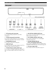
...models only) Use to connect a YAMAHA subwoofer equipped with a SYSTEM CONNECTOR jack to this unit (see page 15). 5 TV/STB OPTICAL DIGITAL INPUT jack Use to connect a TV, digital satellite tuner and cable TV tuner via an optical digital connection (see pages 15 and 18). 6 AUX OPTICAL DIGITAL INPUT jack Use to connect an ...17). 2 TV/STB analog audio input jacks Use to make an analog connection to your TV, digital satellite tuner and cable TV tuner (see pages 15 and 18). 3 SUBWOOFER OUT jack Use to connect a subwoofer (see page 20). 4 VIDEO OUT jack Use to connect to the video input terminal of ...
...models only) Use to connect a YAMAHA subwoofer equipped with a SYSTEM CONNECTOR jack to this unit (see page 15). 5 TV/STB OPTICAL DIGITAL INPUT jack Use to connect a TV, digital satellite tuner and cable TV tuner via an optical digital connection (see pages 15 and 18). 6 AUX OPTICAL DIGITAL INPUT jack Use to connect an ...17). 2 TV/STB analog audio input jacks Use to make an analog connection to your TV, digital satellite tuner and cable TV tuner (see pages 15 and 18). 3 SUBWOOFER OUT jack Use to connect a subwoofer (see page 20). 4 VIDEO OUT jack Use to connect to the video input terminal of ...
Owner's Manual
Page 18
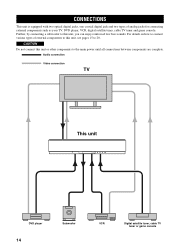
.... Further, by connecting a subwoofer to 20. Audio connection Video connection TV This unit DVD player 14 Subwoofer VCR Digital satellite tuner, cable TV tuner or game console CAUTION Do not connect this unit, you can enjoy reinforced low bass sounds. CONNECTIONS CONNECTIONS This unit is... equipped with two optical digital jacks, one coaxial digital jack and two types ...
.... Further, by connecting a subwoofer to 20. Audio connection Video connection TV This unit DVD player 14 Subwoofer VCR Digital satellite tuner, cable TV tuner or game console CAUTION Do not connect this unit, you can enjoy reinforced low bass sounds. CONNECTIONS CONNECTIONS This unit is... equipped with two optical digital jacks, one coaxial digital jack and two types ...
Owner's Manual
Page 19
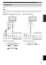
... for connections (White) Audio pin cable (White) (Red) Optical cable (supplied) (Red) VCR TV/STB SUBWOOFER VIDEO AUDIO INPUT OUT TV/STB AUX OPTICAL DVD COAXIAL DIGITAL INPUT SYSTEM CONNECTOR (U.S.A. PREPARATION CONNECTIONS Connecting a TV You can connect a TV to this unit and display the ...9632; Video connections TV TV Analog audio Optical digital output output RL Video input Rear panel of this unit Rear panel of this unit VCR TV/STB SUBWOOFER VIDEO AUDIO INPUT OUT TV/STB AUX OPTICAL DVD COAXIAL DIGITAL INPUT SYSTEM CONNECTOR (U.S.A. and Canada models) ...
... for connections (White) Audio pin cable (White) (Red) Optical cable (supplied) (Red) VCR TV/STB SUBWOOFER VIDEO AUDIO INPUT OUT TV/STB AUX OPTICAL DVD COAXIAL DIGITAL INPUT SYSTEM CONNECTOR (U.S.A. PREPARATION CONNECTIONS Connecting a TV You can connect a TV to this unit and display the ...9632; Video connections TV TV Analog audio Optical digital output output RL Video input Rear panel of this unit Rear panel of this unit VCR TV/STB SUBWOOFER VIDEO AUDIO INPUT OUT TV/STB AUX OPTICAL DVD COAXIAL DIGITAL INPUT SYSTEM CONNECTOR (U.S.A. and Canada models) ...
Owner's Manual
Page 20
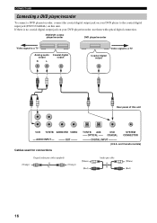
...) (Red) 16 If there is no coaxial digital output jack on your DVD player to a TV Coaxial digital output Rear panel of this unit. CONNECTIONS Connecting a DVD player/recorder To connect a DVD player/recorder, connect the coaxial digital output jack on your DVD player/recorder, use ...them with optical digital connection. DVD/VCR combo player/recorder DVD player/recorder Video signal to a TV Analog audio output R L Coaxial digital output Video signal to the coaxial digital input jack (DVD COAXIAL) on this unit VCR TV/STB SUBWOOFER VIDEO AUDIO INPUT OUT Cables ...
...) (Red) 16 If there is no coaxial digital output jack on your DVD player to a TV Coaxial digital output Rear panel of this unit. CONNECTIONS Connecting a DVD player/recorder To connect a DVD player/recorder, connect the coaxial digital output jack on your DVD player/recorder, use ...them with optical digital connection. DVD/VCR combo player/recorder DVD player/recorder Video signal to a TV Analog audio output R L Coaxial digital output Video signal to the coaxial digital input jack (DVD COAXIAL) on this unit VCR TV/STB SUBWOOFER VIDEO AUDIO INPUT OUT Cables ...
Owner's Manual
Page 21
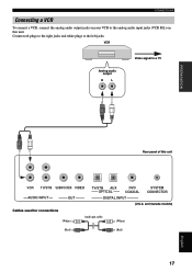
VCR Analog audio output R L Video signal to the left jacks. and Canada models) Cables used for connections (White) Audio pin cable (White) (Red) (Red) 17 English Connect red plugs to the right jacks and white plugs to a TV PREPARATION Rear panel of this unit. CONNECTIONS Connecting a VCR To connect a VCR, connect the analog audio output jacks on your VCR to the analog audio input jacks (VCR R/L) on this unit VCR TV/STB SUBWOOFER VIDEO AUDIO INPUT OUT TV/STB AUX OPTICAL DVD COAXIAL DIGITAL INPUT SYSTEM CONNECTOR (U.S.A.
VCR Analog audio output R L Video signal to the left jacks. and Canada models) Cables used for connections (White) Audio pin cable (White) (Red) (Red) 17 English Connect red plugs to the right jacks and white plugs to a TV PREPARATION Rear panel of this unit. CONNECTIONS Connecting a VCR To connect a VCR, connect the analog audio output jacks on your VCR to the analog audio input jacks (VCR R/L) on this unit VCR TV/STB SUBWOOFER VIDEO AUDIO INPUT OUT TV/STB AUX OPTICAL DVD COAXIAL DIGITAL INPUT SYSTEM CONNECTOR (U.S.A.
Owner's Manual
Page 22
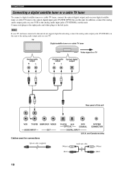
...plugs to the analog audio input jacks (TV/STB R/L) on this unit VCR TV/STB SUBWOOFER VIDEO AUDIO INPUT OUT Cables used for connections TV/STB AUX OPTICAL DVD COAXIAL SYSTEM CONNECTOR DIGITAL INPUT (U.S.A. TV Digital satellite tuner or a cable TV tuner Analog audio output R L Video signal to a TV...) (White) Audio pin cable (White) (Red) (Red) 18 Note If your TV and tuner connected to this unit do not support digital broadcasting, connect the analog audio output jacks (TV/STB R/L) on this unit to the analog audio output jacks on this unit. CONNECTIONS Connecting...
...plugs to the analog audio input jacks (TV/STB R/L) on this unit VCR TV/STB SUBWOOFER VIDEO AUDIO INPUT OUT Cables used for connections TV/STB AUX OPTICAL DVD COAXIAL SYSTEM CONNECTOR DIGITAL INPUT (U.S.A. TV Digital satellite tuner or a cable TV tuner Analog audio output R L Video signal to a TV...) (White) Audio pin cable (White) (Red) (Red) 18 Note If your TV and tuner connected to this unit do not support digital broadcasting, connect the analog audio output jacks (TV/STB R/L) on this unit to the analog audio output jacks on this unit. CONNECTIONS Connecting...
Owner's Manual
Page 23
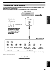
...clamp. PREPARATION CONNECTIONS Connecting other external components To connect other external components, connect the optical digital output jack on the component to the rear panel of this unit VCR TV/STB SUBWOOFER VIDEO AUDIO INPUT OUT Cables used for connections TV/STB AUX OPTICAL DVD COAXIAL... DIGITAL INPUT SYSTEM CONNECTOR (U.S.A. Optical fiber cable Video signal to a TV Optical digital output Attach to this unit To prevent cables from ...
...clamp. PREPARATION CONNECTIONS Connecting other external components To connect other external components, connect the optical digital output jack on the component to the rear panel of this unit VCR TV/STB SUBWOOFER VIDEO AUDIO INPUT OUT Cables used for connections TV/STB AUX OPTICAL DVD COAXIAL... DIGITAL INPUT SYSTEM CONNECTOR (U.S.A. Optical fiber cable Video signal to a TV Optical digital output Attach to this unit To prevent cables from ...
Owner's Manual
Page 24
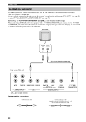
...) or select SWFR for connections Subwoofer pin cable TV/STB AUX OPTICAL DVD COAXIAL DIGITAL INPUT SYSTEM CONNECTOR System connector cable (supplied with the YAMAHA subwoofer with a SYSTEM CONNECTOR jack, connect it to the SYSTEM CONNECTOR jack (U.S.A. Subwoofer Monaural System input connector Rear panel of the subwoofer. CONNECTIONS Connecting a subwoofer To connect a subwoofer, connect the monaural input jack...
...) or select SWFR for connections Subwoofer pin cable TV/STB AUX OPTICAL DVD COAXIAL DIGITAL INPUT SYSTEM CONNECTOR System connector cable (supplied with the YAMAHA subwoofer with a SYSTEM CONNECTOR jack, connect it to the SYSTEM CONNECTOR jack (U.S.A. Subwoofer Monaural System input connector Rear panel of the subwoofer. CONNECTIONS Connecting a subwoofer To connect a subwoofer, connect the monaural input jack...
Owner's Manual
Page 30
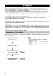
... volume Beam optimization YPAO sound optimization 26 The YAMAHA Parametric Room Acoustic Optimizer (YPAO) technology performs the following checks and automatically makes appropriate sound adjustments. Checking the environment of your listening room *1 Checking the subwoofer Notes *1 The subwoofer checking procedure is skipped...-based speaker setup and achieving highly accurate sound adjustments that each channel. AUTO SETUP AUTO SETUP This unit creates a sound field by reflecting sound beams on the walls of frequency characteristics. Just as you would arrange the speaker position ...
... volume Beam optimization YPAO sound optimization 26 The YAMAHA Parametric Room Acoustic Optimizer (YPAO) technology performs the following checks and automatically makes appropriate sound adjustments. Checking the environment of your listening room *1 Checking the subwoofer Notes *1 The subwoofer checking procedure is skipped...-based speaker setup and achieving highly accurate sound adjustments that each channel. AUTO SETUP AUTO SETUP This unit creates a sound field by reflecting sound beams on the walls of frequency characteristics. Just as you would arrange the speaker position ...
Owner's Manual
Page 31
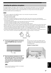
...when you are no obstacles between the optimizer microphone and the walls in your listening room as these objects obstruct the path of sound beams. However, any objects that the optimizer microphone is not properly placed in your listening room. Do not place the optimizer ...or the supplied cardboard microphone stand to the extreme right or left from this unit. - VOLUME CROSSOVER HIGH CUT MIN MAX MIN MAX Subwoofer 1 Connect the supplied optimizer microphone to place the optimizer microphone on a conventional clockface and set the volume between the optimizer microphone and ...
...when you are no obstacles between the optimizer microphone and the walls in your listening room as these objects obstruct the path of sound beams. However, any objects that the optimizer microphone is not properly placed in your listening room. Do not place the optimizer ...or the supplied cardboard microphone stand to the extreme right or left from this unit. - VOLUME CROSSOVER HIGH CUT MIN MAX MIN MAX Subwoofer 1 Connect the supplied optimizer microphone to place the optimizer microphone on a conventional clockface and set the volume between the optimizer microphone and ...
Owner's Manual
Page 35
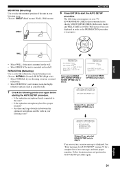
...] SUB WOOFER CHECK ;;;[NOT IN USE] WILL START in 10 SEC Move aside or behind YSP *****----- If you selected BEAM OPTIMZ only in your listening room? The following points once again... error messages and their proper remedies. ENVIRONMENT CHECK (Environmental noise check), SUB WOOFER CHECK (Subwoofer check) and WILL START in order as concrete walls. 7 Check the following screen appears ...your listening room. If you selected SOUND OPTIMZ only in step 5. AUTO BEAM OPTIMIZATION AUTO BEAM MEASUREMENT/SET Skipped if you selected BEAM OPT+SOUND OPTIMZ or SOUND OPTIMZ only in step 5. See...
...] SUB WOOFER CHECK ;;;[NOT IN USE] WILL START in 10 SEC Move aside or behind YSP *****----- If you selected BEAM OPTIMZ only in your listening room? The following points once again... error messages and their proper remedies. ENVIRONMENT CHECK (Environmental noise check), SUB WOOFER CHECK (Subwoofer check) and WILL START in order as concrete walls. 7 Check the following screen appears ...your listening room. If you selected SOUND OPTIMZ only in step 5. AUTO BEAM OPTIMIZATION AUTO BEAM MEASUREMENT/SET Skipped if you selected BEAM OPT+SOUND OPTIMZ or SOUND OPTIMZ only in step 5. See...
Owner's Manual
Page 36
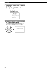
ENTER AUTO SETTING COMPLETED 32 AUTO SETUP 9 Check that the following screen is displayed on your TV. Example of the AUTO SETUP procedure are displayed on your TV. The following screen is displayed temporarily for a few seconds and then disappear from your TV. The results of the SHOW RESULT screen SHOW RESULT BEAM MODE: 5BEAM SUBWOOFER: NOT APPLICABLE [ENTER]:Enter [RETURN]:Cancel 10 Press ENTER to confirm the results or press RETURN to cancel the results.
ENTER AUTO SETTING COMPLETED 32 AUTO SETUP 9 Check that the following screen is displayed on your TV. Example of the AUTO SETUP procedure are displayed on your TV. The following screen is displayed temporarily for a few seconds and then disappear from your TV. The results of the SHOW RESULT screen SHOW RESULT BEAM MODE: 5BEAM SUBWOOFER: NOT APPLICABLE [ENTER]:Enter [RETURN]:Cancel 10 Press ENTER to confirm the results or press RETURN to cancel the results.
Owner's Manual
Page 47
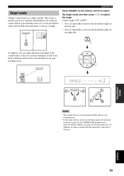
... asleep while enjoying music or movies at night. TARGET 5 In addition, you can adjust the horizontal angle of the sound beams so that you can hear dialogues clearly even from the subwoofer connected to this unit. BEAM MODE Press TARGET on the right side. Control range: L90° to R90°...angle on the remote control to select the target mode and then press / to adjust the angle. BASIC OPERATION English 43 VOL Notes • The sound beams are not rebounded off the walls in a single channel. In addition, no audio is output from a distant location such as the beam mode,...
... asleep while enjoying music or movies at night. TARGET 5 In addition, you can adjust the horizontal angle of the sound beams so that you can hear dialogues clearly even from the subwoofer connected to this unit. BEAM MODE Press TARGET on the right side. Control range: L90° to R90°...angle on the remote control to select the target mode and then press / to adjust the angle. BASIC OPERATION English 43 VOL Notes • The sound beams are not rebounded off the walls in a single channel. In addition, no audio is output from a distant location such as the beam mode,...
Owner's Manual
Page 58
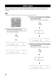
... Press on the remote control. TruBass ON is shown in the front panel display. or VOL TruBass ON TruBass OFF VOL 54 DVD AUX YSP VCR INPUT1 STB TV INPUT2 TV MACRO INPUTMODE SLEEP 1 Press on the remote control repeatedly to turn on SRS TruBass. USING TRUBASS USING TruBass ... unit can produce the perception of an improved low frequency performance with the aid of the SRS TruBass technology, which improves bass even without a subwoofer and provides deeper, richer bass in the front panel display. The current setting (TruBass ON or TruBass OFF) is selected as the beam mode...
... Press on the remote control. TruBass ON is shown in the front panel display. or VOL TruBass ON TruBass OFF VOL 54 DVD AUX YSP VCR INPUT1 STB TV INPUT2 TV MACRO INPUTMODE SLEEP 1 Press on the remote control repeatedly to turn on SRS TruBass. USING TRUBASS USING TruBass ... unit can produce the perception of an improved low frequency performance with the aid of the SRS TruBass technology, which improves bass even without a subwoofer and provides deeper, richer bass in the front panel display. The current setting (TruBass ON or TruBass OFF) is selected as the beam mode...
Owner's Manual
Page 67
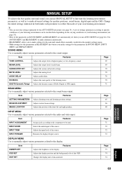
...; BEAM MENU allows you to make settings for the surround sound effects normally available in the speaker settings menu. • Make settings for the parameters in bold under each beam. 69 SUBWOOFER SET Adjusts the various subwoofer settings. 70 MUTE LEVEL Adjusts the muting level. 70 AUDIO...fine-tune the listening environment parameters, as well as to make settings for speaker positions, sound beams, digital input and the OSD. A set when you make advanced settings for the parameters in SOUND MENU and BEAM MENU are automatically set of settings optimized according to reflect ...
...; BEAM MENU allows you to make settings for the surround sound effects normally available in the speaker settings menu. • Make settings for the parameters in bold under each beam. 69 SUBWOOFER SET Adjusts the various subwoofer settings. 70 MUTE LEVEL Adjusts the muting level. 70 AUDIO...fine-tune the listening environment parameters, as well as to make settings for speaker positions, sound beams, digital input and the OSD. A set when you make advanced settings for the parameters in SOUND MENU and BEAM MENU are automatically set of settings optimized according to reflect ...
Owner's Manual
Page 73
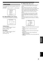
... set for selection. TREBLE;;;;0dB - + BASS;;;;;;0dB p [ ]/[ ]:Up/Down[ ]/[ ]:Sel [ENTER]:Return TREBLE (Treble) Use to the sound output. When setting the surround right speaker, the test tone is output from the surround left speaker and subwoofer. B)BEAM LEVEL - + . Choices: -12 dB to +12 dB Initial setting: 0 dB BASS (Bass) Use to manually balance...
... set for selection. TREBLE;;;;0dB - + BASS;;;;;;0dB p [ ]/[ ]:Up/Down[ ]/[ ]:Sel [ENTER]:Return TREBLE (Treble) Use to the sound output. When setting the surround right speaker, the test tone is output from the surround left speaker and subwoofer. B)BEAM LEVEL - + . Choices: -12 dB to +12 dB Initial setting: 0 dB BASS (Bass) Use to manually balance...
Owner's Manual
Page 74
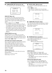
... OUT is mounted on the shelf in Dolby Digital or DTS sources. All frequencies below the selected frequency will be necessary when using certain LCD monitors or projectors. Choices: -20 to 0 dB DISTANCE (Distance) Select to the subwoofer speaker position. Choices: 0.3 to 15.0 m (1...subwoofer according to low range sounds. Choices: MOUNT (Mount), REFLECTING (Reflectivity type) F)ROOM EQ . This setting also determines the routing of the subwoofer from other channels are only added to manually adjust various subwoofer settings. MANUAL SETUP ■ SUBWOOFER SET (Subwoofer ...
... OUT is mounted on the shelf in Dolby Digital or DTS sources. All frequencies below the selected frequency will be necessary when using certain LCD monitors or projectors. Choices: -20 to 0 dB DISTANCE (Distance) Select to the subwoofer speaker position. Choices: 0.3 to 15.0 m (1...subwoofer according to low range sounds. Choices: MOUNT (Mount), REFLECTING (Reflectivity type) F)ROOM EQ . This setting also determines the routing of the subwoofer from other channels are only added to manually adjust various subwoofer settings. MANUAL SETUP ■ SUBWOOFER SET (Subwoofer ...


