
Owner's Manual
Page 5
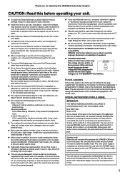
...of power. Condensation might cause a fire, damage to this unit in a cool, dry, clean place - G Secure placement or installation is faulty. YAMAHA shall not be liable for any accident caused by vibrations and breaks, it may fall . For details, refer to obstruct heat radiation. G Install ... away from the mains lead must be set . 1 in power amplifier, heat will radiate from the wall outlet. G Do not place this YAMAHA Subwoofer System. G Do not cover the rear panel of the unit. It might damage the finish. It might impair picture color. G Super-bass ...
...of power. Condensation might cause a fire, damage to this unit in a cool, dry, clean place - G Secure placement or installation is faulty. YAMAHA shall not be liable for any accident caused by vibrations and breaks, it may fall . For details, refer to obstruct heat radiation. G Install ... away from the mains lead must be set . 1 in power amplifier, heat will radiate from the wall outlet. G Do not place this YAMAHA Subwoofer System. G Do not cover the rear panel of the unit. It might damage the finish. It might impair picture color. G Super-bass ...

Owner's Manual
Page 6
... (pin jack) terminals of the amplifier. • For the effective use of your stereo system. • This subwoofer can select bass effect suitable for various listening conditions by using the B.A.S.S. button. 2 CONTENTS SAFETY INSTRUCTIONS II UNPACKING IV... POWER-SWITCHING FUNCTION 9 ADJUSTING THE SUBWOOFER BEFORE USE 10 Frequency characteristics 11 ADVANCED YAMAHA ACTIVE SERVO TECHNOLOGY 12 TROUBLESHOOTING 13 SPECIFICATIONS 14 FEATURES • This subwoofer system employs Advanced YAMAHA Active Servo Technology which YAMAHA has developed for reproducing higher quality ...
... (pin jack) terminals of the amplifier. • For the effective use of your stereo system. • This subwoofer can select bass effect suitable for various listening conditions by using the B.A.S.S. button. 2 CONTENTS SAFETY INSTRUCTIONS II UNPACKING IV... POWER-SWITCHING FUNCTION 9 ADJUSTING THE SUBWOOFER BEFORE USE 10 Frequency characteristics 11 ADVANCED YAMAHA ACTIVE SERVO TECHNOLOGY 12 TROUBLESHOOTING 13 SPECIFICATIONS 14 FEATURES • This subwoofer system employs Advanced YAMAHA Active Servo Technology which YAMAHA has developed for reproducing higher quality ...

Owner's Manual
Page 7
...the bottom of the room. along the walls. PLACEMENT Å ı Ç ( : subwoofer, : main speaker) One subwoofer will have been developed between two parallel walls and they cancel the bass sounds. It also may cancel...See fig. ı.) The placement shown in fig. Ç is also possible, however, if the subwoofer system is recommended to place it on the outside of either the right or the left main speaker. (...See fig. Å.) If using two subwoofers, it and the sound reflected by the wall may be necessary to break up the parallel ...
...the bottom of the room. along the walls. PLACEMENT Å ı Ç ( : subwoofer, : main speaker) One subwoofer will have been developed between two parallel walls and they cancel the bass sounds. It also may cancel...See fig. ı.) The placement shown in fig. Ç is also possible, however, if the subwoofer system is recommended to place it on the outside of either the right or the left main speaker. (...See fig. Å.) If using two subwoofers, it and the sound reflected by the wall may be necessary to break up the parallel ...

Owner's Manual
Page 8
...SPEAKER-S 2 + /MONO + - - + FROM AMPLIFIER INPUT 1 Amplifier To AC outlet SPLIT SUBWOOFER SUBWOOFER (LOW PASS) 4 *Illustration shows YST-SW205. Also refer to the owner's manual for each of your components. • Basically, connect the subwoofer to the line output (pin jack) terminal(s) of the amplifier. (Refer to pages 4 and 5... Connect the main speakers to the speaker output terminals of the amplifier. • To connect with a YAMAHA DSP amplifier (or AV receiver), connect the SUBWOOFER (or LOW PASS etc.) terminal on the rear of the DSP amplifier (or AV receiver) to the...
...SPEAKER-S 2 + /MONO + - - + FROM AMPLIFIER INPUT 1 Amplifier To AC outlet SPLIT SUBWOOFER SUBWOOFER (LOW PASS) 4 *Illustration shows YST-SW205. Also refer to the owner's manual for each of your components. • Basically, connect the subwoofer to the line output (pin jack) terminal(s) of the amplifier. (Refer to pages 4 and 5... Connect the main speakers to the speaker output terminals of the amplifier. • To connect with a YAMAHA DSP amplifier (or AV receiver), connect the SUBWOOFER (or LOW PASS etc.) terminal on the rear of the DSP amplifier (or AV receiver) to the...

Owner's Manual
Page 9
... INPUT 1 POWER ON OFF OUTPUT INPUT + T-O SPEAKER-S 2 + /MONO + - - + FROM AMPLIFIER INPUT 1 SPLIT SUBWOOFER Amplifier To AC outlet To AC outlet *Illustration shows YST-SW205. Notes • Some amplifiers have line output terminals labeled PRE OUT. If the amplifier has only one set of the amplifier..., connect the L/MONO INPUT2 terminal. 5 Instead, connect the subwoofer to the speaker output terminals of...
... INPUT 1 POWER ON OFF OUTPUT INPUT + T-O SPEAKER-S 2 + /MONO + - - + FROM AMPLIFIER INPUT 1 SPLIT SUBWOOFER Amplifier To AC outlet To AC outlet *Illustration shows YST-SW205. Notes • Some amplifiers have line output terminals labeled PRE OUT. If the amplifier has only one set of the amplifier..., connect the L/MONO INPUT2 terminal. 5 Instead, connect the subwoofer to the speaker output terminals of...

Owner's Manual
Page 10
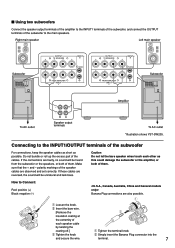
... T-O SPEAKER-S - - INPUT 2 + /MONO + FROM AMPLIFIER INPUT 1 Left main speaker To AC outlet Speaker output terminals A B Amplifier (Both A and B speaker outputs must be ON.) 6 *Illustration shows YST-SW205. Connecting to speaker output terminals of the amplifier I Using one subwoofer If your amplifier has two sets of the...
... T-O SPEAKER-S - - INPUT 2 + /MONO + FROM AMPLIFIER INPUT 1 Left main speaker To AC outlet Speaker output terminals A B Amplifier (Both A and B speaker outputs must be ON.) 6 *Illustration shows YST-SW205. Connecting to speaker output terminals of the amplifier I Using one subwoofer If your amplifier has two sets of the...
Owner's Manual
Page 11
... AMPLIFIER INPUT 1 OUTPUT INPUT + T-O SPEAKER-S 2 + /MONO + - - + FROM AMPLIFIER INPUT 1 Amplifier Subwoofer OUTPUT INPUT AUTO PHASE + T-O SPEAKER-S 2 STANDBY + /MONO + - - + OFF HIGH LOW NORM REV FROM AMPLIFIER INPUT 1 POWER ON OFF To AC outlet Speaker output terminals To AC outlet *Illustration shows YST-SW205. Do not bundle or roll up the excess part of them...
... AMPLIFIER INPUT 1 OUTPUT INPUT + T-O SPEAKER-S 2 + /MONO + - - + FROM AMPLIFIER INPUT 1 Amplifier Subwoofer OUTPUT INPUT AUTO PHASE + T-O SPEAKER-S 2 STANDBY + /MONO + - - + OFF HIGH LOW NORM REV FROM AMPLIFIER INPUT 1 POWER ON OFF To AC outlet Speaker output terminals To AC outlet *Illustration shows YST-SW205. Do not bundle or roll up the excess part of them...
Owner's Manual
Page 12
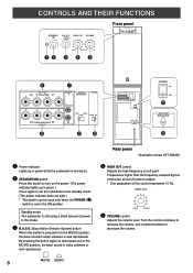
... small amount of this button to set the subwoofer in the standby mode. (The power indicator does not light.) * This button can be used only when the POWER (%) switch is set in the ON position. Rear panel *Illustration shows YST-SW205. ⁄ HIGH CUT control Adjusts the high... Hz. ON MOVIE MUSIC HIGH CUT VOLUME Front panel SUPERWOOFER SYSTEM YST-SW205 STANDBY/ B.A.S.S. Turn the control clockwise to increase the volume, and counterclockwise to the MUSIC position, the bass sound in green while the subwoofer is well reproduced. Frequencies higher than the frequency selected by this...
... small amount of this button to set the subwoofer in the standby mode. (The power indicator does not light.) * This button can be used only when the POWER (%) switch is set in the ON position. Rear panel *Illustration shows YST-SW205. ⁄ HIGH CUT control Adjusts the high... Hz. ON MOVIE MUSIC HIGH CUT VOLUME Front panel SUPERWOOFER SYSTEM YST-SW205 STANDBY/ B.A.S.S. Turn the control clockwise to increase the volume, and counterclockwise to the MUSIC position, the bass sound in green while the subwoofer is well reproduced. Frequencies higher than the frequency selected by this...
Owner's Manual
Page 13
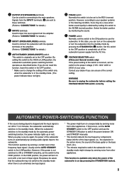
...need this function, leave this switch in the OFF position. * Make sure to change by sensing noise from other appliances. If that the subwoofer may be a case when better sound quality is obtained by setting this switch is incorrect, set to the OFF position. AUTOMATIC POWER-SWITCHING ...between ON and STANDBY manually. * This function detects the low-frequency components below . In this switch to the HIGH or LOW position, the subwoofer's automatic power-switching function operates as described below 200 Hz of the input signals (i.e., the explosion in the action movie, the sound of the...
...need this function, leave this switch in the OFF position. * Make sure to change by sensing noise from other appliances. If that the subwoofer may be a case when better sound quality is obtained by setting this switch is incorrect, set to the OFF position. AUTOMATIC POWER-SWITCHING ...between ON and STANDBY manually. * This function detects the low-frequency components below . In this switch to the HIGH or LOW position, the subwoofer's automatic power-switching function operates as described below 200 Hz of the input signals (i.e., the explosion in the action movie, the sound of the...

Owner's Manual
Page 14
... clearer. (The sound will be obtained, adjust the HIGH CUT control and the VOLUME control again. *Illustration shows YST-SW205. 7 Set the PHASE switch to obtain the optimum volume and tone balance between the subwoofer and the main speakers is played, the low-frequency effects are cut off to the REV (reverse) position...
... clearer. (The sound will be obtained, adjust the HIGH CUT control and the VOLUME control again. *Illustration shows YST-SW205. 7 Set the PHASE switch to obtain the optimum volume and tone balance between the subwoofer and the main speakers is played, the low-frequency effects are cut off to the REV (reverse) position...

Owner's Manual
Page 15
... 500Hz 80 40Hz 140Hz 0 10 * One graduation of this 70 control represents 10 Hz. 60 PHASE-Set to the REV 50 (reverse) position. 40 20 YST-SW205 Main speaker's response 50 100 200 500Hz EX.2 When combined with an 8" or 10" (20 cm or 25 cm) acoustic suspension, 2 way system main speakers... combined with a typical main speaker system. Frequency characteristics This subwoofer's frequency characteristics YST-SW305 dB HIGH CUT 40 Hz HIGH CUT 90 Hz 90 HIGH CUT 140 Hz 80 70 60 50 40 20 50 100 200 500Hz YST-SW205 dB HIGH CUT 90 Hz 90 HIGH CUT 140 Hz 80 70 60 HIGH...
... 500Hz 80 40Hz 140Hz 0 10 * One graduation of this 70 control represents 10 Hz. 60 PHASE-Set to the REV 50 (reverse) position. 40 20 YST-SW205 Main speaker's response 50 100 200 500Hz EX.2 When combined with an 8" or 10" (20 cm or 25 cm) acoustic suspension, 2 way system main speakers... combined with a typical main speaker system. Frequency characteristics This subwoofer's frequency characteristics YST-SW305 dB HIGH CUT 40 Hz HIGH CUT 90 Hz 90 HIGH CUT 140 Hz 80 70 60 50 40 20 50 100 200 500Hz YST-SW205 dB HIGH CUT 90 Hz 90 HIGH CUT 140 Hz 80 70 60 HIGH...
Owner's Manual
Page 17
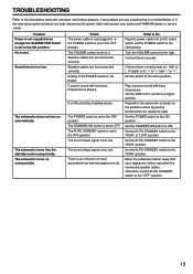
...mode unexpectedly. Connect them correctly, that is set to the OFF position. Play a source sound with few bass frequencies is played. Reposition the subwoofer or break up the parallel surface by standing waves. Otherwise, set the POWER switch to the ON position. TROUBLESHOOTING Refer to the chart below... do not help, disconnect the power cable and contact your authorized YAMAHA dealer or service center. If the problem you are experiencing is set to the ON position. Problem Power is not supplied even though ...
...mode unexpectedly. Connect them correctly, that is set to the OFF position. Play a source sound with few bass frequencies is played. Reposition the subwoofer or break up the parallel surface by standing waves. Otherwise, set the POWER switch to the ON position. TROUBLESHOOTING Refer to the chart below... do not help, disconnect the power cable and contact your authorized YAMAHA dealer or service center. If the problem you are experiencing is set to the ON position. Problem Power is not supplied even though ...


