A150 Desiccated Case
Page 1
A150 Desiccated Case 4/11 Copyright © 2011 Campbell Scientific, Inc.
A150 Desiccated Case 4/11 Copyright © 2011 Campbell Scientific, Inc.
A150 Desiccated Case
Page 2
... corresponding Campbell invoice. Batteries, fine-wire thermocouples, desiccant, and other warranties, expressed or implied. Campbell is not liable for any returns until we receive this warranty is for installation services performed by Campbell such as programming to customer specifications, electrical connections to modification, misuse, neglect, improper service, accidents of nature, or shipping damage. The following contact information is limited to any Campbell products which Campbell Scientific...
... corresponding Campbell invoice. Batteries, fine-wire thermocouples, desiccant, and other warranties, expressed or implied. Campbell is not liable for any returns until we receive this warranty is for installation services performed by Campbell such as programming to customer specifications, electrical connections to modification, misuse, neglect, improper service, accidents of nature, or shipping damage. The following contact information is limited to any Campbell products which Campbell Scientific...
A150 Desiccated Case
Page 3
...A150 with CWS900 Connector 5 8. A150 Wired for links to the printed version of this document. A150 with Continuation Cable 4 5. Use the Adobe Acrobat® bookmarks tab for CS450 Pressure Sensor and CWS900 Connector 5 i CWS900 Connector Pin-Out 3 4. Specifications 3 4. A150 Desiccated Case 1 2. A150 Table of Contents PDF viewers note: These page numbers refer to specific sections. 1. Installation 6 5.1 Mounting 6 5.2 Wiring...6 Figures 1. Anemometer Wired to an A150 5 7. Sensor Hook-up and Example Diagrams 3 4.1 #26972 with PWENC Connector 4 6. A150...
...A150 with CWS900 Connector 5 8. A150 Wired for links to the printed version of this document. A150 with Continuation Cable 4 5. Use the Adobe Acrobat® bookmarks tab for CS450 Pressure Sensor and CWS900 Connector 5 i CWS900 Connector Pin-Out 3 4. Specifications 3 4. A150 Desiccated Case 1 2. A150 Table of Contents PDF viewers note: These page numbers refer to specific sections. 1. Installation 6 5.1 Mounting 6 5.2 Wiring...6 Figures 1. Anemometer Wired to an A150 5 7. Sensor Hook-up and Example Diagrams 3 4.1 #26972 with PWENC Connector 4 6. A150...
A150 Desiccated Case
Page 5
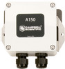
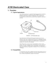
... Cable Gland Mounting Bracket FIGURE 1. The A150 provides a way for a sensor to a datalogger. 1.2 Compatibility As a junction box, the A150 is compatible with most sensors using six wires or less. This allows the sensor more flexibility and range than it would have if it were wired directly to be included in a wireless sensor network. Function 1.1 Typical Applications The A150 desiccated case is attached to the A150...
... Cable Gland Mounting Bracket FIGURE 1. The A150 provides a way for a sensor to a datalogger. 1.2 Compatibility As a junction box, the A150 is compatible with most sensors using six wires or less. This allows the sensor more flexibility and range than it would have if it were wired directly to be included in a wireless sensor network. Function 1.1 Typical Applications The A150 desiccated case is attached to the A150...
A150 Desiccated Case
Page 6
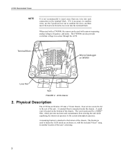
... mounted inside an enclosure or, with sensors measuring analog voltages, frequency, and pulse. When used with a CWS900, the sensor can also provide excitation voltage to Datalogger or CWS900 Lever Nut Vent FIGURE 2. A terminal block is necessary to combine wires, use the 5-position lever nut to combine the wires, and then insert the lead wire from entering the unit...
... mounted inside an enclosure or, with sensors measuring analog voltages, frequency, and pulse. When used with a CWS900, the sensor can also provide excitation voltage to Datalogger or CWS900 Lever Nut Vent FIGURE 2. A terminal block is necessary to combine wires, use the 5-position lever nut to combine the wires, and then insert the lead wire from entering the unit...
A150 Desiccated Case
Page 7
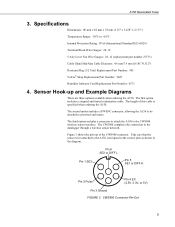
... 3. The CWS900 completes the connection to prewired enclosures. CWS900 Connector Pin-Out 3 Sensor Hook-up and Example Diagrams There are three options available when ordering the A150. The second option includes a PWENC connector, allowing the A150 to be attached to the datalogger through a wireless sensor network. The first option includes a stripped and tinned continuation cable. A150 Desiccated Case 3. Specifications Dimensions: 80 mm x 82...
... 3. The CWS900 completes the connection to prewired enclosures. CWS900 Connector Pin-Out 3 Sensor Hook-up and Example Diagrams There are three options available when ordering the A150. The second option includes a PWENC connector, allowing the A150 to be attached to the datalogger through a wireless sensor network. The first option includes a stripped and tinned continuation cable. A150 Desiccated Case 3. Specifications Dimensions: 80 mm x 82...
A150 Desiccated Case
Page 8
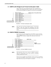
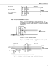
WHITE BLUE GREEN RED BLACK CLEAR #26972 Cable 1 (Pin #) 2 3 #22018 4 PWENC Connector 5 6 BLACK FIGURE 5. Note that the green wire in the PWENC connector must be connected to a datalogger's pulse input inside the enclosure for the signal to a PWENC connector, ensure the wiring inside the pre-wired enclosure corresponds with the wiring from the sensor. A150 with a PWENC connector attached. It is up to the installer to take into account any...
WHITE BLUE GREEN RED BLACK CLEAR #26972 Cable 1 (Pin #) 2 3 #22018 4 PWENC Connector 5 6 BLACK FIGURE 5. Note that the green wire in the PWENC connector must be connected to a datalogger's pulse input inside the enclosure for the signal to a PWENC connector, ensure the wiring inside the pre-wired enclosure corresponds with the wiring from the sensor. A150 with a PWENC connector attached. It is up to the installer to take into account any...
A150 Desiccated Case
Page 9
... the A150 while the CWS900 wireless sensor interface completes the connection to the wireless sensor network. Note how multiple grounds are combined into a single lead wire using the lever nut. A150 Wired for CS450 Pressure Sensor and CWS900 Connector 5 BLACK N.C. A150 Desiccated Case Anemometer BLACK Signal Pulse WHITE Signal Reference CLEAR Shield WHITE BLUE GREEN RED BLACK CLEAR #26972 Cable 1 (Pin #) 2 3 #22018 4 PWENC Connector 5 6 FIGURE 6. WHITE BLUE GREEN RED BLACK CLEAR #26972 Cable 5 (Pin #) 2 1 #19520 4 CWS900 Connector 3 6 BLACK...
... the A150 while the CWS900 wireless sensor interface completes the connection to the wireless sensor network. Note how multiple grounds are combined into a single lead wire using the lever nut. A150 Wired for CS450 Pressure Sensor and CWS900 Connector 5 BLACK N.C. A150 Desiccated Case Anemometer BLACK Signal Pulse WHITE Signal Reference CLEAR Shield WHITE BLUE GREEN RED BLACK CLEAR #26972 Cable 1 (Pin #) 2 3 #22018 4 PWENC Connector 5 6 FIGURE 6. WHITE BLUE GREEN RED BLACK CLEAR #26972 Cable 5 (Pin #) 2 1 #19520 4 CWS900 Connector 3 6 BLACK...

A150 Desiccated Case
Page 10
... datalogger or CWS900. The second option is to use the mounting bracket on the back of each wire to the terminal block adjacent to the corresponding wire to use the Velcro® strap included with the sensor, or contact a Campbell Scientific Applications Engineer, for mounting. Once all wires are attached, tighten the wire gland to combine multiple ground wires into a single wire connection.
... datalogger or CWS900. The second option is to use the mounting bracket on the back of each wire to the terminal block adjacent to the corresponding wire to use the Velcro® strap included with the sensor, or contact a Campbell Scientific Applications Engineer, for mounting. Once all wires are attached, tighten the wire gland to combine multiple ground wires into a single wire connection.
