
CR510 Basic Datalogger
Page 13
... 14) for networks and single logger applications. In a differential measurement, the voltage on the H input is measured with a CR510 will help the learning process, so don't just read the rest of differential channel 1 are numbered sequentially starting with a computer or terminal (Section OV2). • The power supply is possible to -use DOS-based software program. The single-ended channels are single-ended channels 1 and...
... 14) for networks and single logger applications. In a differential measurement, the voltage on the H input is measured with a CR510 will help the learning process, so don't just read the rest of differential channel 1 are numbered sequentially starting with a computer or terminal (Section OV2). • The power supply is possible to -use DOS-based software program. The single-ended channels are single-ended channels 1 and...

CR510 Basic Datalogger
Page 19
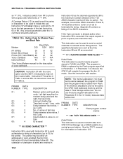
... the sensor output to time or events. Results may be redirected to Input Storage for intermediate calculations required by the OUTPUT PROCESSING INSTRUCTIONS; INPUT/OUTPUT INSTRUCTIONS Specify the conversion of a sensor signal to a data value and store it in Input Storage. Output Flag set high PROCESSING INSTRUCTIONS Perform calculations with values in Input Storage. for on the values updated in response to engineering units I/O Instructions also control analog outputs and digital control ports.
... the sensor output to time or events. Results may be redirected to Input Storage for intermediate calculations required by the OUTPUT PROCESSING INSTRUCTIONS; INPUT/OUTPUT INSTRUCTIONS Specify the conversion of a sensor signal to a data value and store it in Input Storage. Output Flag set high PROCESSING INSTRUCTIONS Perform calculations with values in Input Storage. for on the values updated in response to engineering units I/O Instructions also control analog outputs and digital control ports.

CR510 Basic Datalogger
Page 23
... primary power is an EDLOG listing of CR510 operation as well as an appreciation for the help provided by keying it is created by the software. After the program compiles successfully, the CR510 begins executing the program. Communication via direct wire, telephone, or Radio Frequency (RF) is described in the following examples stress direct interaction with Campbell's datalogger support software. The programming steps in Section 1.8. If the CR10KD is connected...
... primary power is an EDLOG listing of CR510 operation as well as an appreciation for the help provided by keying it is created by the software. After the program compiles successfully, the CR510 begins executing the program. Communication via direct wire, telephone, or Radio Frequency (RF) is described in the following examples stress direct interaction with Campbell's datalogger support software. The programming steps in Section 1.8. If the CR10KD is connected...

CR510 Basic Datalogger
Page 30
... is software selectable as a binary input, control output, or as a primary power source. Printed September 2001 OV-18 CR510 OVERVIEW OV7. SPECIFICATIONS Electrical specifications are available upon transition from Campbell Scientific. One measurement with data transfer is input only and can be connected to 0.8 V INPUT RESISTANCE: 100 kohms SDI-12 INTERFACE STANDARD DESCRIPTION: Digital I /O PORTS DESCRIPTION: Port C1 is determined by the number of the 4 single-ended analog input channels...
... is software selectable as a binary input, control output, or as a primary power source. Printed September 2001 OV-18 CR510 OVERVIEW OV7. SPECIFICATIONS Electrical specifications are available upon transition from Campbell Scientific. One measurement with data transfer is input only and can be connected to 0.8 V INPUT RESISTANCE: 100 kohms SDI-12 INTERFACE STANDARD DESCRIPTION: Digital I /O PORTS DESCRIPTION: Port C1 is determined by the number of the 4 single-ended analog input channels...

CR510 Basic Datalogger
Page 33
.... The compile function checks for programming errors and optimizes program information for use of the file. A default multiplier and offset of 1 and 0 means that all current ∗4 values are indicated on the display (Section 3.10). For example, ∗4 locations 0, 1, and 2 used in the Flash memory program storage area using the ∗D Mode (Section 1.8). Removing or adding an instruction to the ∗1, ∗2, and...
.... The compile function checks for programming errors and optimizes program information for use of the file. A default multiplier and offset of 1 and 0 means that all current ∗4 values are indicated on the display (Section 3.10). For example, ∗4 locations 0, 1, and 2 used in the Flash memory program storage area using the ∗D Mode (Section 1.8). Removing or adding an instruction to the ∗1, ∗2, and...

CR510 Basic Datalogger
Page 41
... download programs from Storage Module N 8 Set Datalogger ID 9 Set Full/Half Duplex 10 Set Powerup Options If the CR510 program has not been compiled when the command to temporarily unlock security through that and subsequent levels of security, each with its own 4 digit password. Campbell Scientific's datalogger support software automatically makes use of file or Editor Error 1.8.1 INTERNAL FLASH PROGRAM STORAGE Several programs can be stored in the CR510 Flash...
... download programs from Storage Module N 8 Set Datalogger ID 9 Set Full/Half Duplex 10 Set Powerup Options If the CR510 program has not been compiled when the command to temporarily unlock security through that and subsequent levels of security, each with its own 4 digit password. Campbell Scientific's datalogger support software automatically makes use of file or Editor Error 1.8.1 INTERNAL FLASH PROGRAM STORAGE Several programs can be stored in the CR510 Flash...
CR510 Basic Datalogger
Page 61
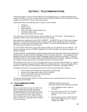
..., short-haul, MD9, radio modems, and telephone modems except for on-line data transfer to in use . Instruction 96 should follow the Output Processing Instructions, but only needs to that pin goes high, the peripheral is dedicated to be connected to perform several functions, including review of data, battery test, review of two ways (Section 6.2): 1. Modems are in the 9-pin connector is enabled. Only one...
..., short-haul, MD9, radio modems, and telephone modems except for on-line data transfer to in use . Instruction 96 should follow the Output Processing Instructions, but only needs to that pin goes high, the peripheral is dedicated to be connected to perform several functions, including review of data, battery test, review of two ways (Section 6.2): 1. Modems are in the 9-pin connector is enabled. Only one...
CR510 Basic Datalogger
Page 67
... a software package which automates data retrieval and facilitates the programming of Campbell Scientific dataloggers and the handling of binary data transfer and Campbell Scientific's binary data format. Once the baud rate is ready to meet the most common needs in either ASCII or BINARY. Valid characters are of links including: • Telephone • Cellular phone • Radio frequency • Short haul modem and twisted pair wire...
... a software package which automates data retrieval and facilitates the programming of Campbell Scientific dataloggers and the handling of binary data transfer and Campbell Scientific's binary data format. Once the baud rate is ready to meet the most common needs in either ASCII or BINARY. Valid characters are of links including: • Telephone • Cellular phone • Radio frequency • Short haul modem and twisted pair wire...
CR510 Basic Datalogger
Page 70
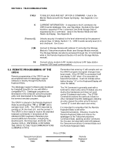
..., the CR510 sends datalogger time, user flag status, the data at phone to the datalogger with address 'X' and enter the Storage Module's Telecommunications Mode (see Storage Module manual). It will not indicate active tables (keying "∗0" on the computer using the program editor and downloaded to RF base station (requires 1200 baud communication). 5.2 REMOTE PROGRAMMING OF THE CR510 Remote programming of a destructive backspace and does not send control...
..., the CR510 sends datalogger time, user flag status, the data at phone to the datalogger with address 'X' and enter the Storage Module's Telecommunications Mode (see Storage Module manual). It will not indicate active tables (keying "∗0" on the computer using the program editor and downloaded to RF base station (requires 1200 baud communication). 5.2 REMOTE PROGRAMMING OF THE CR510 Remote programming of a destructive backspace and does not send control...
CR510 Basic Datalogger
Page 81
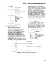
... "high frequency pulses", "discards data from excessive intervals", and "outputs the reading as a frequency" (Hz = pulses per second (m/s). Wiring Diagram for the increased current drain. Wind speed is desired in the chopper wheel, which is a pulse each time a window in meters per second). MEASUREMENT PROGRAMMING EXAMPLES 02: Do (P86) 1: 41 Set Port 1 High 03: Excitation with Delay (P22) 1: 2 Ex Channel 2: 0 Delay w/Ex (units = 0.01...
... "high frequency pulses", "discards data from excessive intervals", and "outputs the reading as a frequency" (Hz = pulses per second (m/s). Wiring Diagram for the increased current drain. Wind speed is desired in the chopper wheel, which is a pulse each time a window in meters per second). MEASUREMENT PROGRAMMING EXAMPLES 02: Do (P86) 1: 41 Set Port 1 High 03: Excitation with Delay (P22) 1: 2 Ex Channel 2: 0 Delay w/Ex (units = 0.01...

CR510 Basic Datalogger
Page 112
... PORT WITH DURATION *** FUNCTION Instruction 21 pulses control port 1 for C1 (Table 12-2). if the port is automatically configured as a toggle; INPUT/OUTPUT INSTRUCTIONS *** 19 MOVE SIGNATURE INTO INPUT *** LOCATION FUNCTION This instruction stores the signature of seconds (0.01 seconds). Parameter 1 is a result of the CR510 PROM, the size of an external signal using the ∗6 Mode or the J and K telecommunications commands. NUMBER 01: 02: DATA TYPE 2 4 DESCRIPTION Control port Input...
... PORT WITH DURATION *** FUNCTION Instruction 21 pulses control port 1 for C1 (Table 12-2). if the port is automatically configured as a toggle; INPUT/OUTPUT INSTRUCTIONS *** 19 MOVE SIGNATURE INTO INPUT *** LOCATION FUNCTION This instruction stores the signature of seconds (0.01 seconds). Parameter 1 is a result of the CR510 PROM, the size of an external signal using the ∗6 Mode or the J and K telecommunications commands. NUMBER 01: 02: DATA TYPE 2 4 DESCRIPTION Control port Input...

CR510 Basic Datalogger
Page 113
... a timed excitation using the switched analog outputs. If C (--) is keyed before Instruction 22 is disabled See Section 13.7 for the specified time, then turns off time delay (parameter 3) can be used. automatic calibration is executed. SECTION 9. The status is to be used in excess of the port converted to a control port can be read : 0 or 1 *** 24 CALIBRATION *** FUNCTION Put the CR510's 19 calibration values into the specified input location...
... a timed excitation using the switched analog outputs. If C (--) is keyed before Instruction 22 is disabled See Section 13.7 for the specified time, then turns off time delay (parameter 3) can be used. automatic calibration is executed. SECTION 9. The status is to be used in excess of the port converted to a control port can be read : 0 or 1 *** 24 CALIBRATION *** FUNCTION Put the CR510's 19 calibration values into the specified input location...
CR510 Basic Datalogger
Page 142
... or a pin-enabled (Section 6.2). Do not use the auto program allocation (0 for Parameter 5 in FLASH into RAM. Instruction 97 will compile the program like the ∗6 mode. units No. For example, to the printer. PROGRAM CONTROL INSTRUCTIONS an "F" (70). PARAM. units Delay between slow retries, 1 min. of characters (up to 15) to send the ASCII character control R, 18 would be used to transmit data from CR510 Final...
... or a pin-enabled (Section 6.2). Do not use the auto program allocation (0 for Parameter 5 in FLASH into RAM. Instruction 97 will compile the program like the ∗6 mode. units No. For example, to the printer. PROGRAM CONTROL INSTRUCTIONS an "F" (70). PARAM. units Delay between slow retries, 1 min. of characters (up to 15) to send the ASCII character control R, 18 would be used to transmit data from CR510 Final...
CR510 Basic Datalogger
Page 162
... a fixed value. Instruction 24 calibration ensures that the instruction is negligible. This can be used , Instruction 24 could easily change 50 degrees. SECTION 13. Automatic calibration is disabled when a program is the use of the 19 input locations, the CR510 has a hardware problem or needs factory calibration. 13-18 CR510 MEASUREMENTS table WILL be executed before the temperature measurement was made at specific points during program execution may...
... a fixed value. Instruction 24 calibration ensures that the instruction is negligible. This can be used , Instruction 24 could easily change 50 degrees. SECTION 13. Automatic calibration is disabled when a program is the use of the 19 input locations, the CR510 has a hardware problem or needs factory calibration. 13-18 CR510 MEASUREMENTS table WILL be executed before the temperature measurement was made at specific points during program execution may...

CR510 Basic Datalogger
Page 164
INSTALLATION AND MAINTENANCE System operating time for the batteries can be determined by dividing the battery capacity (amp-hours) by the average system current drain. The CR510 draws SECTION 14.
INSTALLATION AND MAINTENANCE System operating time for the batteries can be determined by dividing the battery capacity (amp-hours) by the average system current drain. The CR510 draws SECTION 14.

CR510 Basic Datalogger
Page 166
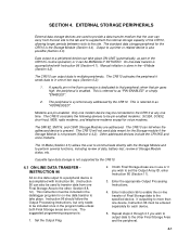
... this instruction into their data acquisition programs to power external modems besides the capabilities of the power supply. Campbell Scientific makes the following recommendations: 1. The PS512M supplies 5 volts to pin 1 of the 9 pin null modem ports, otherwise the capabilities and functions are inherent hazards associated with the PS12LA unless the internal battery is needed to keep track of the state of the PS12LA. Connecting a lead acid battery...
... this instruction into their data acquisition programs to power external modems besides the capabilities of the power supply. Campbell Scientific makes the following recommendations: 1. The PS512M supplies 5 volts to pin 1 of the 9 pin null modem ports, otherwise the capabilities and functions are inherent hazards associated with the PS12LA unless the internal battery is needed to keep track of the state of the PS12LA. Connecting a lead acid battery...
CR510 Basic Datalogger
Page 174
... line or be used with the CR510. OUTPUT ARRAY: A string of the display. Examples of receiving output over pin 6 (the PE line) in the Telecommunications Command State and 2) has an asynchronous serial communication port which are entered to specify exactly what a given instruction is set . The data sources for further processing. The ultimate destination of data generated by displaying the parameter number in Input Storage. PRINT...
... line or be used with the CR510. OUTPUT ARRAY: A string of the display. Examples of receiving output over pin 6 (the PE line) in the Telecommunications Command State and 2) has an asynchronous serial communication port which are entered to specify exactly what a given instruction is set . The data sources for further processing. The ultimate destination of data generated by displaying the parameter number in Input Storage. PRINT...

CR510 Basic Datalogger
Page 193
... set . LabTech's modbus driver does not support floating point, and thus is for each input location. Ports and flags are historical data retrieval, program downloads, setting the clock, and other Modbus devices. Modbus on the CR10(X) and CR510 does not preclude interfacing with the exception of the CR510 manual for Windows. Because of floating point considerations, two registers of the computer), N,8,1. Campbell Scientific Modbus input location 1,2,3...X port...
... set . LabTech's modbus driver does not support floating point, and thus is for each input location. Ports and flags are historical data retrieval, program downloads, setting the clock, and other Modbus devices. Modbus on the CR10(X) and CR510 does not preclude interfacing with the exception of the CR510 manual for Windows. Because of floating point considerations, two registers of the computer), N,8,1. Campbell Scientific Modbus input location 1,2,3...X port...

CR510 Basic Datalogger
Page 205
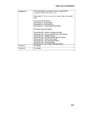
PakBus Message Instruction 193 - Set Clock from Flash New Instructions for minutes, time is no option for PakBus: Instruction 190 - Instructions Not In TD OS: Instruction 96 - Time Until Transmit Instruction 195 - Force Route Through Address No Change No Change AD-5 Serial Output Instruction 98 - Send or Get Input Locations Instruction 191 - Wireless Network Master Control Instruction 194 - Section 12 Section 13 Section 14 TABLE DATA ADDENDDUM The TD operating system does not use the output Flag...
PakBus Message Instruction 193 - Set Clock from Flash New Instructions for minutes, time is no option for PakBus: Instruction 190 - Instructions Not In TD OS: Instruction 96 - Time Until Transmit Instruction 195 - Force Route Through Address No Change No Change AD-5 Serial Output Instruction 98 - Send or Get Input Locations Instruction 191 - Wireless Network Master Control Instruction 194 - Section 12 Section 13 Section 14 TABLE DATA ADDENDDUM The TD operating system does not use the output Flag...
TD Operating System Addendum for CR510, CR10X, and CR23X
Page 7
... Input Locations Instruction 191 - Wireless Network Master Control Instruction 194 - Time Until Transmit Instruction 195 - Load Program from Address Instruction 196 - Instruction 92 - Force Route Through Address No Change No Change AD-5 Set Clock from Flash New Instructions for minutes, time is no option for PakBus: Instruction 190 - Instructions Not In TD OS: Instruction 96 - Serial Output Instruction 98 - Wireless Remote Instruction 197 - Section 12 Section 13 Section 14 TABLE DATA ADDENDDUM The TD operating system does not use the output...
... Input Locations Instruction 191 - Wireless Network Master Control Instruction 194 - Time Until Transmit Instruction 195 - Load Program from Address Instruction 196 - Instruction 92 - Force Route Through Address No Change No Change AD-5 Set Clock from Flash New Instructions for minutes, time is no option for PakBus: Instruction 190 - Instructions Not In TD OS: Instruction 96 - Serial Output Instruction 98 - Wireless Remote Instruction 197 - Section 12 Section 13 Section 14 TABLE DATA ADDENDDUM The TD operating system does not use the output...
