
User Manual
Page 2
... keys and adjusting wrenches are removed from chemically treated lumber. Some examples of the blade or cutter only. 13. Make certain switch is in OFF position before attempting assembly or operation. 2. Do not back stock out of power and overheating. Read and understand entire owner's manual before connecting machine to operate tool. 11. Replace warning labels if they are specifically designed to comply with approved safety...
... keys and adjusting wrenches are removed from chemically treated lumber. Some examples of the blade or cutter only. 13. Make certain switch is in OFF position before attempting assembly or operation. 2. Do not back stock out of power and overheating. Read and understand entire owner's manual before connecting machine to operate tool. 11. Replace warning labels if they are specifically designed to comply with approved safety...
User Manual
Page 3
... parts. Don't use . Check for lubricating and changing accessories. 37. Keep visitors a safe distance from switch whenever band saw is in use in serious injury. 33. Keep work area. injury. A guard or other conditions that can result in dangerous environment. Make your hands. 38. Looking around machine clean and free of unauthorized persons or children. Check damaged parts. Maintain tools with care. Remove safety key from work...
... parts. Don't use . Check for lubricating and changing accessories. 37. Keep visitors a safe distance from switch whenever band saw is in use in serious injury. 33. Keep work area. injury. A guard or other conditions that can result in dangerous environment. Make your hands. 38. Looking around machine clean and free of unauthorized persons or children. Check damaged parts. Maintain tools with care. Remove safety key from work...

User Manual
Page 4
... guides ...19 7.14 Guide post ...20 7.15 Guide post parallelism ...20 7.16 Changing blade speed ...20 7.17 Drive belt replacement and tensioning 21 7.18 Pulley alignment ...21 7.19 Brushes ...21 8.0 Operating controls ...21 8.1 Start/stop ...15 7.5 Leveling table insert ...16 7.6 Installing/changing blades ...16 7.7 Blade tension...17 7.8 Adjusting blade tension lever ...17 7.9 Blade tracking...17 7.10 Overview - 2.0 Table of contents Section Page 1.0 IMPORTANT SAFETY INSTRUCTIONS ...2 2.0 Table of contents...4 3.0 About this manual ...6 4.0 Specifications ...6 4.1 Specifications for JWBS...
... guides ...19 7.14 Guide post ...20 7.15 Guide post parallelism ...20 7.16 Changing blade speed ...20 7.17 Drive belt replacement and tensioning 21 7.18 Pulley alignment ...21 7.19 Brushes ...21 8.0 Operating controls ...21 8.1 Start/stop ...15 7.5 Leveling table insert ...16 7.6 Installing/changing blades ...16 7.7 Blade tension...17 7.8 Adjusting blade tension lever ...17 7.9 Blade tracking...17 7.10 Overview - 2.0 Table of contents Section Page 1.0 IMPORTANT SAFETY INSTRUCTIONS ...2 2.0 Table of contents...4 3.0 About this manual ...6 4.0 Specifications ...6 4.1 Specifications for JWBS...

User Manual
Page 5
....1 JWBS-18/20 Upper Blade Guide Assembly - Exploded View 60 13.20.2 JWBS-20 Upper Wheel Sliding Bracket Assembly - Exploded View 36 13.2.2 JWBS-15 Rip Fence Assembly - Parts List 56 13.18.1 JWBS-20 Upper Wheel Assembly - Parts List 59 13.19.1 JWBS-20 Lower Wheel Assembly - 9.11 Material...24 9.12 Blade breakage ...24 10.0 User-maintenance ...25 10.1 Lubrication points ...25 10.2 Additional servicing ...25 11.0 Blade Selection Guide...26 12.0 Troubleshooting JWBS-series Band Saws 27 12.1 Operational problems ...27 12.2 Mechanical and electrical problems ...29 13.0 Replacement...
....1 JWBS-18/20 Upper Blade Guide Assembly - Exploded View 60 13.20.2 JWBS-20 Upper Wheel Sliding Bracket Assembly - Exploded View 36 13.2.2 JWBS-15 Rip Fence Assembly - Parts List 56 13.18.1 JWBS-20 Upper Wheel Assembly - Parts List 59 13.19.1 JWBS-20 Lower Wheel Assembly - 9.11 Material...24 9.12 Blade breakage ...24 10.0 User-maintenance ...25 10.1 Lubrication points ...25 10.2 Additional servicing ...25 11.0 Blade Selection Guide...26 12.0 Troubleshooting JWBS-series Band Saws 27 12.1 Operational problems ...27 12.2 Mechanical and electrical problems ...29 13.0 Replacement...
User Manual
Page 6
... reference. If there are used in accordance with the instructions as set forth in this manual before attempting assembly or operation! Your machine has been designed and constructed to comply may cause serious injury! 4.0 Specifications The specifications in this document. This manual contains instructions on installation, safety precautions, general operating procedures, maintenance instructions and parts breakdown. Additional knowledge can also be obtained from experienced users or trade articles.
... reference. If there are used in accordance with the instructions as set forth in this manual before attempting assembly or operation! Your machine has been designed and constructed to comply may cause serious injury! 4.0 Specifications The specifications in this document. This manual contains instructions on installation, safety precautions, general operating procedures, maintenance instructions and parts breakdown. Additional knowledge can also be obtained from experienced users or trade articles.

User Manual
Page 7
... load amps 15/7.5A 12A Starting amps 75A 52A Running amps (no load 5.1A 2.4A Start capacitor 300MFD 250VAC 300MFD 250VAC Run capacitor 40μF 250VAC 60μF 300VAC Power transfer poly v-belt poly v-belt On/off switch push button with fence 12-3/8 in. (316 mm 12-3/8 in . Maximum blade width 1 in 1 in . max. 133.5) Minimum blade width 1/8 in 1/8 in . (750 x 812 x 1880 mm).......... Miter gauge angle Left...
... load amps 15/7.5A 12A Starting amps 75A 52A Running amps (no load 5.1A 2.4A Start capacitor 300MFD 250VAC 300MFD 250VAC Run capacitor 40μF 250VAC 60μF 300VAC Power transfer poly v-belt poly v-belt On/off switch push button with fence 12-3/8 in. (316 mm 12-3/8 in . Maximum blade width 1 in 1 in . max. 133.5) Minimum blade width 1/8 in 1/8 in . (750 x 812 x 1880 mm).......... Miter gauge angle Left...

User Manual
Page 8
... A Starting amps 75A 53A Running amps (no load 5.1A 2.4A Start capacitor 300MFD 250VAC 300MFD 250VAC Run capacitor 40μF 250VAC 60μF 300VAC Power transfer poly v-belt poly v-belt On/off switch push button with fence 4-1/2 in 4-1/2 in . Table tilt Left 5°, Right 45 Left 5°, Right 45° Table height from blade, without load Capacities and speeds: Wheel diameter 18-1/2 in 18-1/2 in . 4.2 Specifications for JWBS-18 Model number JWBS...
... A Starting amps 75A 53A Running amps (no load 5.1A 2.4A Start capacitor 300MFD 250VAC 300MFD 250VAC Run capacitor 40μF 250VAC 60μF 300VAC Power transfer poly v-belt poly v-belt On/off switch push button with fence 4-1/2 in 4-1/2 in . Table tilt Left 5°, Right 45 Left 5°, Right 45° Table height from blade, without load Capacities and speeds: Wheel diameter 18-1/2 in 18-1/2 in . 4.2 Specifications for JWBS-18 Model number JWBS...

User Manual
Page 9
...) Dust collection: Dust port outside diameter 4 in. (100mm) x 2 4 in . min. 157.1) Blade width 1/8 to 1-1/2 in 1/8 to make a better estimation of blade with fence 18-1/2 in. (470 mm 18-1/2 in. (470 mm) Maximum rip right of the hazards and risks involved only. 9 W x 0.35 in . H Resaw fence size LxWxH 22.5 x 6.1 x 1.8 in 22.5 x 6.1 x 1.8 in . 4.3 Specifications for JWBS-20 Model number JWBS-20-3 JWBS-20-5 Stock number 714800 714850 Band saw nominal size 20 in 20...
...) Dust collection: Dust port outside diameter 4 in. (100mm) x 2 4 in . min. 157.1) Blade width 1/8 to 1-1/2 in 1/8 to make a better estimation of blade with fence 18-1/2 in. (470 mm 18-1/2 in. (470 mm) Maximum rip right of the hazards and risks involved only. 9 W x 0.35 in . H Resaw fence size LxWxH 22.5 x 6.1 x 1.8 in 22.5 x 6.1 x 1.8 in . 4.3 Specifications for JWBS-20 Model number JWBS-20-3 JWBS-20-5 Stock number 714800 714850 Band saw nominal size 20 in 20...
User Manual
Page 11
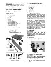
... adjustment of the machine from power source during assembly procedures. Failure to its permanent working location. E 1 Lifting ring - HP3 4 Lock washers - Move the saw off skid. HP6 5.2 Tools required for assembly The tools listed below are not included but are required for assembly. 1 2.5mm hex key 1 3mm hex key 1 straight edge 1 17mm wrench 1 13mm wrench 5.3 Unpacking and cleanup Remove crate and packing material from band saw blade passes through 5-4: 1. C 1 Table insert - D 1 Guide rail - G 1 Miter gauge assembly...
... adjustment of the machine from power source during assembly procedures. Failure to its permanent working location. E 1 Lifting ring - HP3 4 Lock washers - Move the saw off skid. HP6 5.2 Tools required for assembly The tools listed below are not included but are required for assembly. 1 2.5mm hex key 1 3mm hex key 1 straight edge 1 17mm wrench 1 13mm wrench 5.3 Unpacking and cleanup Remove crate and packing material from band saw blade passes through 5-4: 1. C 1 Table insert - D 1 Guide rail - G 1 Miter gauge assembly...
User Manual
Page 12
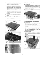
... table edge. If adjustment is parallel to blade: Move blade tension lever to miter slot. 5. Check that table is needed , until fence adjustments have been made in Figure 7-9), and place a long straightedge flush against edge of table - Figure 5-3 5.7 Installing guide rail Refer to right of fence. Loosen and rotate hex nuts on guide rail studs. 2. Slide fence body (A, Figure 5-7) onto guide rail and move fence body to Figure 5-6. 1. Hand tighten screws only. 3. Install slot handle assembly (HP6), and tighten...
... table edge. If adjustment is parallel to blade: Move blade tension lever to miter slot. 5. Check that table is needed , until fence adjustments have been made in Figure 7-9), and place a long straightedge flush against edge of table - Figure 5-3 5.7 Installing guide rail Refer to right of fence. Loosen and rotate hex nuts on guide rail studs. 2. Slide fence body (A, Figure 5-7) onto guide rail and move fence body to Figure 5-6. 1. Hand tighten screws only. 3. Install slot handle assembly (HP6), and tighten...
User Manual
Page 13
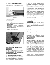
... from the factory for use of table and tighten screws. Repair or replace damaged or worn cord immediately. Failure to comply may be grounded. 5.9 Table bracket (JWBS-20 only) Install bracket (J, Figure 5-8) to back edge of electric shock. Figure 5-8 5.10 Miter gauge Refer to 90 degrees. 5. Tighten screw. The conductor with a qualified electrician or service personnel if the grounding instructions are wired from the adaptor must be used to connect this...
... from the factory for use of table and tighten screws. Repair or replace damaged or worn cord immediately. Failure to comply may be grounded. 5.9 Table bracket (JWBS-20 only) Install bracket (J, Figure 5-8) to back edge of electric shock. Figure 5-8 5.10 Miter gauge Refer to 90 degrees. 5. Tighten screw. The conductor with a qualified electrician or service personnel if the grounding instructions are wired from the adaptor must be used to connect this...

User Manual
Page 14
... Table 1 for the amperage listed on the machine's motor plate. Switch the motor lead wires inside the junction box cover. 2. No adapter is available or should be replaced with a 230V plug should comply with the appropriate amperage rating. Recommended Gauges (AWG) of Extension Cords Ampere Rating Volts Total length of power and overheating. If the tool must be reconnected for use on a different type of electric circuit...
... Table 1 for the amperage listed on the machine's motor plate. Switch the motor lead wires inside the junction box cover. 2. No adapter is available or should be replaced with a 230V plug should comply with the appropriate amperage rating. Recommended Gauges (AWG) of Extension Cords Ampere Rating Volts Total length of power and overheating. If the tool must be reconnected for use on a different type of electric circuit...
User Manual
Page 17
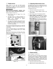
..., clockwise to tighten, counterclockwise to 3/16 in Full Tension position. 2. Move lever to position of your blade. Models JWBS-15 and JWBS-18: Turn adjust- "Tracking" refers to Blade Release position and remove blade. 3. 7.7 Blade tension Blade tension is set the blade tension to correspond to Partial Tension position - Disconnect machine from power source. 2. Set blade tension by hand with the saw is 1/8 to Figures 7-13 and 7-14. Model JWBS-20: Move stop bushing (Figure...
..., clockwise to tighten, counterclockwise to 3/16 in Full Tension position. 2. Move lever to position of your blade. Models JWBS-15 and JWBS-18: Turn adjust- "Tracking" refers to Blade Release position and remove blade. 3. 7.7 Blade tension Blade tension is set the blade tension to correspond to Partial Tension position - Disconnect machine from power source. 2. Set blade tension by hand with the saw is 1/8 to Figures 7-13 and 7-14. Model JWBS-20: Move stop bushing (Figure...
User Manual
Page 20
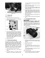
... saw from power source. 2. Confirm that bottom of the guide post; Verify the setting by the manufacturer and should already be set screws (P) as enhance operator safety. 4. For lower blade-speed - place poly V-belt in inner position on pulleys. After repositioning belt: 5. The JWBS-18 and JWBS-20 band saws have two blade-speed options which will maintain their relationship to blade (see sect. 7.4). 4. Loosen lock handle (A, Figure 7-21). thus the guide...
... saw from power source. 2. Confirm that bottom of the guide post; Verify the setting by the manufacturer and should already be set screws (P) as enhance operator safety. 4. For lower blade-speed - place poly V-belt in inner position on pulleys. After repositioning belt: 5. The JWBS-18 and JWBS-20 band saws have two blade-speed options which will maintain their relationship to blade (see sect. 7.4). 4. Loosen lock handle (A, Figure 7-21). thus the guide...
User Manual
Page 21
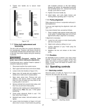
... 8-1 - Loosen motor lock handle (A, Figure 7-21). 4. Install new belt, making any adjustments. It should be occasionally checked when the band saw is new, as follows: 1. Loosen screw and adjust as follows: An adjustable brush is done in or out. 4. Check tension by sliding in conjunction with poly Vbelt replacement. Raise motor lift handle (B) and retighten lock handle (A) to hold motor in raised position. 8.0 Operating controls 8.1 Start/stop button (B) to remove it. 6. Remove old belt from...
... 8-1 - Loosen motor lock handle (A, Figure 7-21). 4. Install new belt, making any adjustments. It should be occasionally checked when the band saw is new, as follows: 1. Loosen screw and adjust as follows: An adjustable brush is done in or out. 4. Check tension by sliding in conjunction with poly Vbelt replacement. Raise motor lift handle (B) and retighten lock handle (A) to hold motor in raised position. 8.0 Operating controls 8.1 Start/stop button (B) to remove it. 6. Remove old belt from...

User Manual
Page 22
... piece must not be re-inserted before band saw . Using the fence in conjunction with the miter gauge can operate. 9.0 Operation The following figures may or may cause the blade to blade. Make sure the blade and upper and lower bearings are just above workpiece (about 3/16") allowing minimum exposure to break. 6. Turn on 1-3/4 HP models.) The switch has a safety feature that the guide bearings are properly adjusted...
... piece must not be re-inserted before band saw . Using the fence in conjunction with the miter gauge can operate. 9.0 Operation The following figures may or may cause the blade to blade. Make sure the blade and upper and lower bearings are just above workpiece (about 3/16") allowing minimum exposure to break. 6. Turn on 1-3/4 HP models.) The switch has a safety feature that the guide bearings are properly adjusted...
User Manual
Page 25
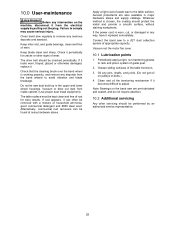
... and blade breakage. If the power cord is worn, cut, or damaged in any way, have it from the electrical supply by an authorized service representative. 25 Oil any deposits from inside cabinet. (Use proper dust mask equipment). Keep blade clean and sharp. Whatever method is working properly, and remove any pins, shafts, and joints. (Do not get oil on pulleys or belts.) 4. Grease sliding surfaces...
... and blade breakage. If the power cord is worn, cut, or damaged in any way, have it from the electrical supply by an authorized service representative. 25 Oil any deposits from inside cabinet. (Use proper dust mask equipment). Keep blade clean and sharp. Whatever method is working properly, and remove any pins, shafts, and joints. (Do not get oil on pulleys or belts.) 4. Grease sliding surfaces...
User Manual
Page 27
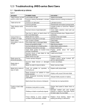
... spring is worn; Replace belt if worn. Align fence properly. Increase tension. Contact service representative. Blade binds in workpiece. Worn blade teeth or damaged blade. Saw dust or debris on blade not perfectly aligned. Sharpen blade properly or replace. Table vibration while sawing. Cuts not straight. Blade pitch too coarse. Blade too wide for band wheel diameter. Adjust blade guides properly. Position guides about 1/8" above workpiece. Replace trunnion locking mechanism. Check blade selection chart and use correct blade...
... spring is worn; Replace belt if worn. Align fence properly. Increase tension. Contact service representative. Blade binds in workpiece. Worn blade teeth or damaged blade. Saw dust or debris on blade not perfectly aligned. Sharpen blade properly or replace. Table vibration while sawing. Cuts not straight. Blade pitch too coarse. Blade too wide for band wheel diameter. Adjust blade guides properly. Position guides about 1/8" above workpiece. Replace trunnion locking mechanism. Check blade selection chart and use correct blade...
User Manual
Page 29
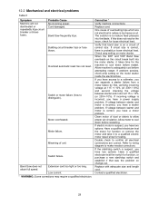
... motor is correct, you have a motor problem. Refer to wiring diagram to reduce feed pressure into the motor starter, it to a voltmeter, you have access to a qualified electric motor repair shop for testing. Probable Cause No incoming power. Cord damaged. Overload automatic reset has not reset. Verify that was the problem on the circuit break built into the blade. 12.2 Mechanical and electrical problems Table 5 Symptom Machine will not start /stop switch...
... motor is correct, you have a motor problem. Refer to wiring diagram to reduce feed pressure into the motor starter, it to a voltmeter, you have access to a qualified electric motor repair shop for testing. Probable Cause No incoming power. Cord damaged. Overload automatic reset has not reset. Verify that was the problem on the circuit break built into the blade. 12.2 Mechanical and electrical problems Table 5 Symptom Machine will not start /stop switch...

User Manual
Page 33
...-135 Socket Head Cap Screw M4x8 8 36 JWBS15-136 Lower Door ...1 37 PM1800B-027-026.... Safety Key for JOSS-S-213 (not shown 1 JWBS15-143B........... Contactor Switch 1 JWBS15-146OP........ Dust Collect Insert 1 33 Description Size Qty 1 PM1500-004 Lifting Ring M10 1 2 JWBS15-102 Machine Main Body Frame 1 3 TS-1482021 Hex Cap Bolt M6x12 1 4 JWBS15-104 Power Cord 1-3/4HP 1 JWBS15-104B........... Parts List Index...
...-135 Socket Head Cap Screw M4x8 8 36 JWBS15-136 Lower Door ...1 37 PM1800B-027-026.... Safety Key for JOSS-S-213 (not shown 1 JWBS15-143B........... Contactor Switch 1 JWBS15-146OP........ Dust Collect Insert 1 33 Description Size Qty 1 PM1500-004 Lifting Ring M10 1 2 JWBS15-102 Machine Main Body Frame 1 3 TS-1482021 Hex Cap Bolt M6x12 1 4 JWBS15-104 Power Cord 1-3/4HP 1 JWBS15-104B........... Parts List Index...


