

English Manual
Page 1
PFRW3914.0 Serial No. Serial Number Decal ACTIVATE YOUR WARRANTY To activate your warranty today, go to www.proformservice.com/ registration. CUSTOMER CARE For service at any time, go to www.proformservice.com. MT Please do not contact the store. Keep this equipment. Or call 1-888-533-1333 Mon.-Fri. 6 a.m.-6 p.m. CAUTION Read all precautions and instructions in the space above for future reference. MT Sat. 8 a.m.-12 p.m. Write the serial number in this manual before using this manual for reference. www.proform.com Model No. USER'S MANUAL
PFRW3914.0 Serial No. Serial Number Decal ACTIVATE YOUR WARRANTY To activate your warranty today, go to www.proformservice.com/ registration. CUSTOMER CARE For service at any time, go to www.proformservice.com. MT Please do not contact the store. Keep this equipment. Or call 1-888-533-1333 Mon.-Fri. 6 a.m.-6 p.m. CAUTION Read all precautions and instructions in the space above for future reference. MT Sat. 8 a.m.-12 p.m. Write the serial number in this manual before using this manual for reference. www.proform.com Model No. USER'S MANUAL

English Manual
Page 2
... shown at actual size. Apply the decal in the location shown. PROFORM is missing or illegible, see the front cover of ICON IP, Inc. 2 TABLE OF CONTENTS WARNING DECAL PLACEMENT 2 IMPORTANT PRECAUTIONS 3 BEFORE YOU BEGIN 5 PART IDENTIFICATION CHART 6 ASSEMBLY 7 HOW TO USE THE ROWER 14 FCC INFORMATION 17 MAINTENANCE AND TROUBLESHOOTING 18 EXERCISE GUIDELINES 19 PART LIST 22 EXPLODED DRAWING 23 ORDERING REPLACEMENT PARTS Back Cover LIMITED WARRANTY Back Cover WARNING DECAL...
... shown at actual size. Apply the decal in the location shown. PROFORM is missing or illegible, see the front cover of ICON IP, Inc. 2 TABLE OF CONTENTS WARNING DECAL PLACEMENT 2 IMPORTANT PRECAUTIONS 3 BEFORE YOU BEGIN 5 PART IDENTIFICATION CHART 6 ASSEMBLY 7 HOW TO USE THE ROWER 14 FCC INFORMATION 17 MAINTENANCE AND TROUBLESHOOTING 18 EXERCISE GUIDELINES 19 PART LIST 22 EXPLODED DRAWING 23 ORDERING REPLACEMENT PARTS Back Cover LIMITED WARRANTY Back Cover WARNING DECAL...

English Manual
Page 3
..., or institutional setting. 5. Wear appropriate clothes while exercising; Do not put the rower in serious injury or death. ICON assumes no responsibility for foot protection. 10. The rower should not be used by or through the use the rower in this product. 1. Do not release the row bar while the cord is at all parts regularly. Do not use of clearance around...
..., or institutional setting. 5. Wear appropriate clothes while exercising; Do not put the rower in serious injury or death. ICON assumes no responsibility for foot protection. 10. The rower should not be used by or through the use the rower in this product. 1. Do not release the row bar while the cord is at all parts regularly. Do not use of clearance around...
English Manual
Page 5
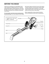
... cm) Row Bar Frame Knob Frame Pin Seat Rail Console Resistance Control Foot Plate Wheel Pedal 5 If you enjoy this manual carefully before you , note the product model number and serial number before contacting us assist you use the rower. The 440 R rower is an effective exercise for selecting the new PROFORM® 440 R rower. The model number and the location of the serial number decal are shown on the front cover of this manual. Length...
... cm) Row Bar Frame Knob Frame Pin Seat Rail Console Resistance Control Foot Plate Wheel Pedal 5 If you enjoy this manual carefully before you , note the product model number and serial number before contacting us assist you use the rower. The 440 R rower is an effective exercise for selecting the new PROFORM® 440 R rower. The model number and the location of the serial number decal are shown on the front cover of this manual. Length...

English Manual
Page 6
... x 20mm Washer (47)-2 M13 x 22mm Washer (33)-2 WMa1s3hexr3(28m8)m-1 6 The number in the hardware kit, check to identify the small parts needed for assembly. PART IDENTIFICATION CHART Use the drawings below each drawing is the key number of the part, from the PART LIST near the end of this manual. Note: If a part is not in parentheses below to see if it has been...
... x 20mm Washer (47)-2 M13 x 22mm Washer (33)-2 WMa1s3hexr3(28m8)m-1 6 The number in the hardware kit, check to identify the small parts needed for assembly. PART IDENTIFICATION CHART Use the drawings below each drawing is the key number of the part, from the PART LIST near the end of this manual. Note: If a part is not in parentheses below to see if it has been...

English Manual
Page 7
... persons. • Place all assembly steps. • To identify small parts, see the front cover of wrenches. ASSEMBLY • To hire an authorized service technician to assemble this manual) and register your warranty • saves you time if you ever need to contact Customer Care • allows us to notify you of upgrades and offers Note: If you do not use power tools. 1.
... persons. • Place all assembly steps. • To identify small parts, see the front cover of wrenches. ASSEMBLY • To hire an authorized service technician to assemble this manual) and register your warranty • saves you time if you ever need to contact Customer Care • allows us to notify you of upgrades and offers Note: If you do not use power tools. 1.

English Manual
Page 8
...press the Nut Cap (55) onto the 1/2" Locknut (54). 45 55 54 33 39 41 8 33 36 8 3. Note: The parts that you removed will be used in step 3. Remove the Frame Pin (37) from the Frame (39). Orient the Rail (8) as shown. 4 Attach the Rail Bracket (41) to the Frame (39) with the 1/2" x 100mm Bolt... (36), the two M13 x 22mm Washers (33), and the 1/2" Locknut (54) that you removed in steps 4 and 5. 3 37 54 33 39 33 36 4. Then, remove the 1/2" Locknut (54), the two M13 x 22mm Washers (33), and the 1/2" x 100mm Bolt (36) from the Frame (39). Next, unwrap the Bungee Cord ...
...press the Nut Cap (55) onto the 1/2" Locknut (54). 45 55 54 33 39 41 8 33 36 8 3. Note: The parts that you removed will be used in step 3. Remove the Frame Pin (37) from the Frame (39). Orient the Rail (8) as shown. 4 Attach the Rail Bracket (41) to the Frame (39) with the 1/2" x 100mm Bolt... (36), the two M13 x 22mm Washers (33), and the 1/2" Locknut (54) that you removed in steps 4 and 5. 3 37 54 33 39 33 36 4. Then, remove the 1/2" Locknut (54), the two M13 x 22mm Washers (33), and the 1/2" x 100mm Bolt (36) from the Frame (39). Next, unwrap the Bungee Cord ...

English Manual
Page 9
Move the Seat (28) to the front of the Rail (8). 5 Have a second person raise the Rail (8) to the Rail (8) with two M8 x 20mm Screws (14) and two M8 x 6 3 20mm Washers (16). 14 16 8 9 5. Fully insert the Frame Pin (37) into the indicated hole in the Rail Bracket (41) so that it holds the Rail in place. 8 28 37 41 Hole 6. Attach the Rear Stabilizer (3) to the vertical position.
Move the Seat (28) to the front of the Rail (8). 5 Have a second person raise the Rail (8) to the Rail (8) with two M8 x 20mm Screws (14) and two M8 x 6 3 20mm Washers (16). 14 16 8 9 5. Fully insert the Frame Pin (37) into the indicated hole in the Rail Bracket (41) so that it holds the Rail in place. 8 28 37 41 Hole 6. Attach the Rear Stabilizer (3) to the vertical position.

English Manual
Page 10
7. Attach the Bungee Clip (97) to the Rear Stabilizer (3) with an M5 x 10mm Screw (101). 8 101 2 3 3 5 45 10 Attach the Rear Stabilizer Cover (2) to the indicated hole in the Rail Attachment Bracket (43). 7 3 45 97 Hole 43 8. Make sure that the Bungee Cord (45) is not twisted. See the inset drawing. Route the end of the Bungee Cord (45) around the Small Pulley (5) on the Rear Stabilizer (3) as shown.
7. Attach the Bungee Clip (97) to the Rear Stabilizer (3) with an M5 x 10mm Screw (101). 8 101 2 3 3 5 45 10 Attach the Rear Stabilizer Cover (2) to the indicated hole in the Rail Attachment Bracket (43). 7 3 45 97 Hole 43 8. Make sure that the Bungee Cord (45) is not twisted. See the inset drawing. Route the end of the Bungee Cord (45) around the Small Pulley (5) on the Rear Stabilizer (3) as shown.

English Manual
Page 11
9. Orient the Rail Cover (18) as shown. 9 Attach the Rail Cover (18) to the floor. 10 Next, insert the Frame Pin (37) into the Frame (39) and into the Rail Bracket (41). 8 87 37 88 39 41 11 Then, slide an M13 x 32mm Washer (88) onto the Frame Knob (87), insert the Frame Knob into the Frame (39), and tighten the Frame Knob into the Rail Bracket (41). Remove the Frame Pin (37) from the Rail Bracket (41), and lower the Rail (8) to the Rail (8) with four M5 x 8mm Screws (12). 12 8 18 12 10.
9. Orient the Rail Cover (18) as shown. 9 Attach the Rail Cover (18) to the floor. 10 Next, insert the Frame Pin (37) into the Frame (39) and into the Rail Bracket (41). 8 87 37 88 39 41 11 Then, slide an M13 x 32mm Washer (88) onto the Frame Knob (87), insert the Frame Knob into the Frame (39), and tighten the Frame Knob into the Rail Bracket (41). Remove the Frame Pin (37) from the Rail Bracket (41), and lower the Rail (8) to the Rail (8) with four M5 x 8mm Screws (12). 12 8 18 12 10.

English Manual
Page 12
Then, tighten an M8 Acorn Nut (31) onto each end of the Stop Rod (35) at the same time. 12 57 31 58 39 32 33 13. Insert a Pedal Strap (29) through the buckle on the Frame (39) and center it . Then, route the end of the Pedal Axle. Next, slide an M8 x 20mm Washer (16) and... M13 x 22mm Washer (33) onto each side of the Stop Rod (35). Attach the other Pedal Strap (29) to the Left Pedal (57) in the same way. 29 57 30 16 15 31 29 30 12 Next, identify the Right Pedal (30) and the Left Pedal (57). Then, tighten an M8 Acorn Nut (31) onto each side of...
Then, tighten an M8 Acorn Nut (31) onto each end of the Stop Rod (35) at the same time. 12 57 31 58 39 32 33 13. Insert a Pedal Strap (29) through the buckle on the Frame (39) and center it . Then, route the end of the Pedal Axle. Next, slide an M8 x 20mm Washer (16) and... M13 x 22mm Washer (33) onto each side of the Stop Rod (35). Attach the other Pedal Strap (29) to the Left Pedal (57) in the same way. 29 57 30 16 15 31 29 30 12 Next, identify the Right Pedal (30) and the Left Pedal (57). Then, tighten an M8 Acorn Nut (31) onto each side of...

English Manual
Page 13
... the screw, and press the Console into the battery compartment; alkaline batteries are properly tightened before you insert batteries. age the console display or other Foot Plate (not shown) to protect the floor. 13 Then, reattach the battery cover with a Foot Plate Pin (51). 14 Attach the other electronic components. The Console (66) requires two AA batteries (not included); Otherwise, you use old and new batteries together...
... the screw, and press the Console into the battery compartment; alkaline batteries are properly tightened before you insert batteries. age the console display or other Foot Plate (not shown) to protect the floor. 13 Then, reattach the battery cover with a Foot Plate Pin (51). 14 Attach the other electronic components. The Console (66) requires two AA batteries (not included); Otherwise, you use old and new batteries together...

English Manual
Page 14
... the pedals, and adjust the straps to the floor. Correct rowing form consists of your chest. The third phase is the DRIVE. never hold your feet. Hold the row bar with your exercise, you can adjust the resis- Your legs should be nearly straight. HOW TO MOVE THE ROWER Stand behind the rower and lift the rear stabilizer until your chest. To increase the resistance, turn the resistance control...
... the pedals, and adjust the straps to the floor. Correct rowing form consists of your chest. The third phase is the DRIVE. never hold your feet. Hold the row bar with your exercise, you can adjust the resis- Your legs should be nearly straight. HOW TO MOVE THE ROWER Stand behind the rower and lift the rear stabilizer until your chest. To increase the resistance, turn the resistance control...

English Manual
Page 15
... holds the Rail in a location where children cannot tip it. To store the rower, first see assembly step 10 on page 9. Remove the batteries from the console when storing the rower for extended periods of time. Remove the Frame Knob (87) and the M13 x 32mm Washer (88). Next, see assembly step 10 on page 11. Then, tighten the Frame Knob (87) and the M13...
... holds the Rail in a location where children cannot tip it. To store the rower, first see assembly step 10 on page 9. Remove the batteries from the console when storing the rower for extended periods of time. Remove the Frame Knob (87) and the M13 x 32mm Washer (88). Next, see assembly step 10 on page 11. Then, tighten the Frame Knob (87) and the M13...

English Manual
Page 16
... each, in the console (see assembly step 15 on the console, remove the plastic. 1. To turn off feature. If the row bar does not move and the Mode button is a sheet of calories you exercise, the console will turn on the console, press the Mode button on the console. Calories-This mode shows the approximate number of clear plastic on 13). As you have burned during your workouts. Strokes per minute...
... each, in the console (see assembly step 15 on the console, remove the plastic. 1. To turn off feature. If the row bar does not move and the Mode button is a sheet of calories you exercise, the console will turn on the console, press the Mode button on the console. Calories-This mode shows the approximate number of clear plastic on 13). As you have burned during your workouts. Strokes per minute...

English Manual
Page 17
... installation. These limits are designed to provide reasonable protection against harmful interference in accordance with the limits for help. FCC CAUTION: To assure continued compliance, use only shielded interface cables when connecting to computer or peripheral devices. FCC INFORMATION This equipment has been tested and found to comply with the instructions, may cause harmful interference to radio communications. Changes...
... installation. These limits are designed to provide reasonable protection against harmful interference in accordance with the limits for help. FCC CAUTION: To assure continued compliance, use only shielded interface cables when connecting to computer or peripheral devices. FCC INFORMATION This equipment has been tested and found to comply with the instructions, may cause harmful interference to radio communications. Changes...
English Manual
Page 18
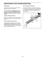
... included grease to the console, keep liquids away from the console and keep the console out of the included grease to a paper towel, and spread a thin layer evenly along the rail where the rollers move. To clean the rower, use the rower, apply a small amount of direct sunlight. Then, wipe off any worn parts immediately. MAINTENANCE AND TROUBLESHOOTING MAINTENANCE Inspect and tighten all parts of low batteries; Then...
... included grease to the console, keep liquids away from the console and keep the console out of the included grease to a paper towel, and spread a thin layer evenly along the rail where the rollers move. To clean the rower, use the rower, apply a small amount of direct sunlight. Then, wipe off any worn parts immediately. MAINTENANCE AND TROUBLESHOOTING MAINTENANCE Inspect and tighten all parts of low batteries; Then...
English Manual
Page 19
... 14, your body uses carbohydrate calories for successful results. During the first few months of your heart rate. WORKOUT GUIDELINES Warming Up-Start with your heart rate near the lowest number in your training zone for persons over age 35 or persons with your heart rate in your training zone. (During the first few minutes of your exercise program, do not keep your heart rate in your...
... 14, your body uses carbohydrate calories for successful results. During the first few months of your heart rate. WORKOUT GUIDELINES Warming Up-Start with your heart rate near the lowest number in your training zone for persons over age 35 or persons with your heart rate in your training zone. (During the first few minutes of your exercise program, do not keep your heart rate in your...
English Manual
Page 22
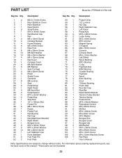
... Bar Reed Switch Bracket Tension Pulley Bracket Tension Spring Frame Knob M13 x 32mm Washer Resistance Control M5 x 35mm Screw M5 Nut M10 x 68mm Screw M4 x 8mm Screw M10 Washer Bungee End Bungee Cover Bungee Clip M8 Washer M10 x 36mm Screw M5 x 60mm Screw M5 x 10mm Screw M4 x 12mm Machine Screw Rail Plate User's Manual Note: Specifications are not illustrated. 22 For information about ordering replacement parts, see the back cover...
... Bar Reed Switch Bracket Tension Pulley Bracket Tension Spring Frame Knob M13 x 32mm Washer Resistance Control M5 x 35mm Screw M5 Nut M10 x 68mm Screw M4 x 8mm Screw M10 Washer Bungee End Bungee Cover Bungee Clip M8 Washer M10 x 36mm Screw M5 x 60mm Screw M5 x 10mm Screw M4 x 12mm Machine Screw Rail Plate User's Manual Note: Specifications are not illustrated. 22 For information about ordering replacement parts, see the back cover...
English Manual
Page 24
... that vary from the date of enjoyment or use and service conditions. Accordingly, the above limitation may have other consequential damages of this warranty is in connection with respect to be the customer's responsibility. ICON Health & Fitness, Inc. (ICON) warrants this manual) • the key number and description of the replacement part(s) (see the PART LIST and the EXPLODED DRAWING near the end of purchase. If...
... that vary from the date of enjoyment or use and service conditions. Accordingly, the above limitation may have other consequential damages of this warranty is in connection with respect to be the customer's responsibility. ICON Health & Fitness, Inc. (ICON) warrants this manual) • the key number and description of the replacement part(s) (see the PART LIST and the EXPLODED DRAWING near the end of purchase. If...


