
Hardware Installation Guide
Page 7
...18 Attaching the Optional Cable Guide 2-19 Installing the Switch on a Wall 2-20 Attaching the Brackets to the Switch 2-21 Mounting the Switch to a Wall 2-22 Powering On the Switch and Running POST 2-24 Connecting to DC Power 2-25 Preparing for Installation 2-25 Grounding the Switch 2-26 Wiring the DC-Input Power Source 2-29 ...Correcting Module POST Failures 3-2 Diagnosing Problems 3-3 Technical Specifications A-1 Connectors and Cable Specifications B-1 Connector Specifications B-1 10/100 Ports B-1 100BASE-FX Ports B-2 Contents 78-6461-04 Catalyst 2900 Series XL Hardware Installation Guide vii
...18 Attaching the Optional Cable Guide 2-19 Installing the Switch on a Wall 2-20 Attaching the Brackets to the Switch 2-21 Mounting the Switch to a Wall 2-22 Powering On the Switch and Running POST 2-24 Connecting to DC Power 2-25 Preparing for Installation 2-25 Grounding the Switch 2-26 Wiring the DC-Input Power Source 2-29 ...Correcting Module POST Failures 3-2 Diagnosing Problems 3-3 Technical Specifications A-1 Connectors and Cable Specifications B-1 Connector Specifications B-1 10/100 Ports B-1 100BASE-FX Ports B-2 Contents 78-6461-04 Catalyst 2900 Series XL Hardware Installation Guide vii
Hardware Installation Guide
Page 9
INDEX Class 1 Laser Product Warning C-22 Laser Beam Exposure Warning C-23 No On/Off Switch Warning C-24 Chassis Warning-Rack-Mounting and Servicing C-25 Reinforced Insulation Warning C-29 LAN Connections Only Warning C-30 No Field-Replaceable Units Warning C-31 Installation Warning C-32 ... Equipment Warning C-36 Ground Connection Warning C-37 Qualified Personnel Warning C-38 DC Power Disconnection Warning C-39 Exposed Wire Lead Warning C-41 Contents 78-6461-04 Catalyst 2900 Series XL Hardware Installation Guide ix
INDEX Class 1 Laser Product Warning C-22 Laser Beam Exposure Warning C-23 No On/Off Switch Warning C-24 Chassis Warning-Rack-Mounting and Servicing C-25 Reinforced Insulation Warning C-29 LAN Connections Only Warning C-30 No Field-Replaceable Units Warning C-31 Installation Warning C-32 ... Equipment Warning C-36 Ground Connection Warning C-37 Qualified Personnel Warning C-38 DC Power Disconnection Warning C-39 Exposed Wire Lead Warning C-41 Contents 78-6461-04 Catalyst 2900 Series XL Hardware Installation Guide ix
Hardware Installation Guide
Page 22
...transfer mode (ATM) modules • On the Catalyst 2924M XL DC switch, a direct current (DC) power converter • On the Catalyst 2912 LRE XL and 2924 LRE XL switches, up to 24 LRE ports through one RJ-21 connector and hot swapping capability with the Cisco LRE customer premises equipment (CPE) devices •...; Supports up to 2048 MAC addresses on the Catalyst 2924 XL, 2924C XL, and 2912 XL switches • Supports up to...
...transfer mode (ATM) modules • On the Catalyst 2924M XL DC switch, a direct current (DC) power converter • On the Catalyst 2912 LRE XL and 2924 LRE XL switches, up to 24 LRE ports through one RJ-21 connector and hot swapping capability with the Cisco LRE customer premises equipment (CPE) devices •...; Supports up to 2048 MAC addresses on the Catalyst 2924 XL, 2924C XL, and 2912 XL switches • Supports up to...
Hardware Installation Guide
Page 23
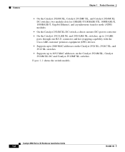
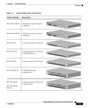
Chapter 1 Product Overview Figure 1-1 Catalyst 2900 Series XL Switches Version Number Description WS-C2912-LRE-XL 4 fixed autosensing 10/100 ports INPUT OUTPUT PWR PWR RESET TEMP FAN 9X 10X 11X 12X 12 LRE ports Cisco RPS 300 WS-C2924-LRE-XL 4 fixed autosensing 10/100 ports 24 LRE ports INPUT OUTPUT PWR PWR ...RESET TEMP FAN 9X 10X 11X 12X Cisco RPS 300 WS-C2912-XL 12 fixed autosensing 10/100 ports MODE 1X 2X 3X 4X 5X 6X 7X 8X 9X 10X 10BaseT/100BASE-TX 11X 12X Catalyst 2900 SERIES XL WS-C2924C...
Chapter 1 Product Overview Figure 1-1 Catalyst 2900 Series XL Switches Version Number Description WS-C2912-LRE-XL 4 fixed autosensing 10/100 ports INPUT OUTPUT PWR PWR RESET TEMP FAN 9X 10X 11X 12X 12 LRE ports Cisco RPS 300 WS-C2924-LRE-XL 4 fixed autosensing 10/100 ports 24 LRE ports INPUT OUTPUT PWR PWR ...RESET TEMP FAN 9X 10X 11X 12X Cisco RPS 300 WS-C2912-XL 12 fixed autosensing 10/100 ports MODE 1X 2X 3X 4X 5X 6X 7X 8X 9X 10X 10BaseT/100BASE-TX 11X 12X Catalyst 2900 SERIES XL WS-C2924C...
Hardware Installation Guide
Page 25
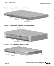
... Overview Figure 1-2 Catalyst 2900 XL Front-Panel 10/100 Ports Front-Panel Description MODE 1X 2X 3X 4X 5X 6X 7X 8X 9X 10X 10BASE-T/100BA1S0E0-BTaXseFX 11X 12X 13X 14X 15X 16X 17X 18X 19X 20X 21X 22X Catalyst10209B0AS0ES-FEXRIES XL 23 24 10/100 ports 100BASE...-FX ports Figure 1-3 Catalyst 2900 XL 100BASE-FX ports and Module Slots Expansion slots 47286 12 1 MODE 2 3 Catalyst 2900 SERIES XL 4 5 100BASE-FX 6 7 8 9 10 11 12 100BASE-...
... Overview Figure 1-2 Catalyst 2900 XL Front-Panel 10/100 Ports Front-Panel Description MODE 1X 2X 3X 4X 5X 6X 7X 8X 9X 10X 10BASE-T/100BA1S0E0-BTaXseFX 11X 12X 13X 14X 15X 16X 17X 18X 19X 20X 21X 22X Catalyst10209B0AS0ES-FEXRIES XL 23 24 10/100 ports 100BASE...-FX ports Figure 1-3 Catalyst 2900 XL 100BASE-FX ports and Module Slots Expansion slots 47286 12 1 MODE 2 3 Catalyst 2900 SERIES XL 4 5 100BASE-FX 6 7 8 9 10 11 12 100BASE-...
Hardware Installation Guide
Page 27
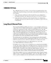
...default mode for half-duplex operation, the connection can be up to 1352 feet (412 meters). • If the switch port and the port on the same Catalyst 2900 LRE XL switch, and you can reach speeds of up to 15 Mbps (full duplex) and distances of up to 6562 feet (2 ... down the switch or disrupting the other telephone services are connected through a basic telephone service, also known as plain old telephone service (POTS) splitter. Chapter 1 Product Overview Front-Panel Description 100BASE-FX Ports The 100BASE-FX ports use one RJ-21 connector to connect up to 24 Cisco LRE customer ...
...default mode for half-duplex operation, the connection can be up to 1352 feet (412 meters). • If the switch port and the port on the same Catalyst 2900 LRE XL switch, and you can reach speeds of up to 15 Mbps (full duplex) and distances of up to 6562 feet (2 ... down the switch or disrupting the other telephone services are connected through a basic telephone service, also known as plain old telephone service (POTS) splitter. Chapter 1 Product Overview Front-Panel Description 100BASE-FX Ports The 100BASE-FX ports use one RJ-21 connector to connect up to 24 Cisco LRE customer ...
Hardware Installation Guide
Page 32
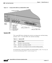
... Figure 1-7 Catalyst 2912 LRE XL and 2924 LRE XL LEDs 10/100 port LEDs Chapter 1 Product Overview SYSTEM RPS MODE LRE STAT DUPLX SPEED Mode button 1X 2X 3X 4X System LED RPS LED LRE LED STAT LED DUPLEX LED Speed LED LRE port LEDs 1-12 LRE port LEDs 13-24 48002... System Status System is operating normally. System is not powered up. For information on the System LED colors during POST, see the "Powering On the Switch and Running POST" section on page 2-24. 1-12 Catalyst 2900 Series XL Hardware Installation Guide 78-6461-04
... Figure 1-7 Catalyst 2912 LRE XL and 2924 LRE XL LEDs 10/100 port LEDs Chapter 1 Product Overview SYSTEM RPS MODE LRE STAT DUPLX SPEED Mode button 1X 2X 3X 4X System LED RPS LED LRE LED STAT LED DUPLEX LED Speed LED LRE port LEDs 1-12 LRE port LEDs 13-24 48002... System Status System is operating normally. System is not powered up. For information on the System LED colors during POST, see the "Powering On the Switch and Running POST" section on page 2-24. 1-12 Catalyst 2900 Series XL Hardware Installation Guide 78-6461-04
Hardware Installation Guide
Page 38
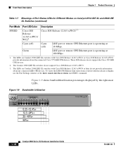
... 6.25 -12.4%+ 12.5 -24%+ 25 - 49%+ 50%+ Catalyst 2900 SERIES XL 1-18 Catalyst 2900 Series XL Hardware Installation Guide 78-6461-04 Figure 1-9 shows bandwidth utilization percentages displayed by the right-most LEDs. The Catalyst 2900 LRE XL switches do not support the Cisco 585 LRE CPE devices. 2.... Product Overview Table 1-7 Meanings of Port Status LEDs for Different Modes on Catalyst 2912 LRE XL and 2924 LRE XL Switches (continued) Port Mode SPEED Port LED Color Cisco IOS Release 12.0(5.x)WC1/ WC21 Description Cisco IOS Release 12.0(5.x)WC42 3 Cyan (off) Cyan (off) LRE port or...
... 6.25 -12.4%+ 12.5 -24%+ 25 - 49%+ 50%+ Catalyst 2900 SERIES XL 1-18 Catalyst 2900 Series XL Hardware Installation Guide 78-6461-04 Figure 1-9 shows bandwidth utilization percentages displayed by the right-most LEDs. The Catalyst 2900 LRE XL switches do not support the Cisco 585 LRE CPE devices. 2.... Product Overview Table 1-7 Meanings of Port Status LEDs for Different Modes on Catalyst 2912 LRE XL and 2924 LRE XL Switches (continued) Port Mode SPEED Port LED Color Cisco IOS Release 12.0(5.x)WC1/ WC21 Description Cisco IOS Release 12.0(5.x)WC42 3 Cyan (off) Cyan (off) LRE port or...
Hardware Installation Guide
Page 44
Power Connectors Chapter 1 Product Overview 1-24 Catalyst 2900 Series XL Hardware Installation Guide 78-6461-04
Power Connectors Chapter 1 Product Overview 1-24 Catalyst 2900 Series XL Hardware Installation Guide 78-6461-04
Hardware Installation Guide
Page 50
...Catalyst 2900 Series XL Hardware Installation Guide 2-6 78-6461-04 Caution There are used and installed properly according to place the switch, be installed on a table or shelf, in the "Powering On the Switch and Running POST" section on /off switch. Installation Guidelines The switch ... special conditions of installation and protection distance are no serviceable parts inside the unit. Before installing the switch, first verify that does not have an on page 2-24. When determining where to the Hungarian EMC Class A requirements (MSZEN55022). Warning Unplug the power cord ...
...Catalyst 2900 Series XL Hardware Installation Guide 2-6 78-6461-04 Caution There are used and installed properly according to place the switch, be installed on a table or shelf, in the "Powering On the Switch and Running POST" section on /off switch. Installation Guidelines The switch ... special conditions of installation and protection distance are no serviceable parts inside the unit. Before installing the switch, first verify that does not have an on page 2-24. When determining where to the Hungarian EMC Class A requirements (MSZEN55022). Warning Unplug the power cord ...
Hardware Installation Guide
Page 52
...or desk - Four number-12 Phillips machine screws for mounting the switch on the switch back panel. (See Figure 1-13.) Catalyst 2900 Series XL Hardware Installation Guide 2-8 78-6461-04 Four rubber feet for attaching the brackets to the switch (24-inch rack mount) - Two mounting brackets - Four number-8 ... The cable guide does not attach to the Catalyst 2912 LRE XL and 2924 LRE XL switches. • One RJ-45-to-DB-9 adapter • Cisco Information Packet, containing warranty, safety, and support information Note In addition to the switch (19-inch rack mount) - Four number-8...
...or desk - Four number-12 Phillips machine screws for mounting the switch on the switch back panel. (See Figure 1-13.) Catalyst 2900 Series XL Hardware Installation Guide 2-8 78-6461-04 Four rubber feet for attaching the brackets to the switch (24-inch rack mount) - Two mounting brackets - Four number-8 ... The cable guide does not attach to the Catalyst 2912 LRE XL and 2924 LRE XL switches. • One RJ-45-to-DB-9 adapter • Cisco Information Packet, containing warranty, safety, and support information Note In addition to the switch (19-inch rack mount) - Four number-8...
Hardware Installation Guide
Page 53
...switch on page 2-24. After the switch is mounted on the table or shelf, power the switch as described in "Powering On the Switch... and Running POST" section on a table or shelf: Step 1 Step 2 Step 3 Locate the adhesive strip with the rubber feet in a partially filled rack, load the rack from the bottom to a 19-, 23-, or 24...-inch rack. Installing the Switch in a Rack Warning To.... Place the switch on brackets for two-rack-unit modular switches. Figure 2-1 ...
...switch on page 2-24. After the switch is mounted on the table or shelf, power the switch as described in "Powering On the Switch... and Running POST" section on a table or shelf: Step 1 Step 2 Step 3 Locate the adhesive strip with the rubber feet in a partially filled rack, load the rack from the bottom to a 19-, 23-, or 24...-inch rack. Installing the Switch in a Rack Warning To.... Place the switch on brackets for two-rack-unit modular switches. Figure 2-1 ...
Hardware Installation Guide
Page 54
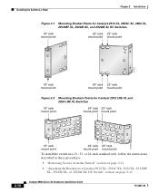
...follow the instructions described in a 19-, 23- Installing the Switch in a Rack Chapter 2 Installation Figure 2-1 Mounting Bracket Points for Catalyst 2912 XL, 2924C XL, 2924 XL, 2912MF XL, 2924M XL, and 2924M XL DC Switches 19" rack mount point 24" rack 23" rack mount point mount point 47307 19"...rack mount point mount point 54725 19" rack mount point 24" rack 23" rack mount point mount point To install the switch in these procedures: • "Removing Screws from the Switch" section on page 2-11 • "Attaching the Brackets to a Catalyst 2912 XL, 2924C XL, 2924 XL, 2912MF XL, ...
...follow the instructions described in a 19-, 23- Installing the Switch in a Rack Chapter 2 Installation Figure 2-1 Mounting Bracket Points for Catalyst 2912 XL, 2924C XL, 2924 XL, 2912MF XL, 2924M XL, and 2924M XL DC Switches 19" rack mount point 24" rack 23" rack mount point mount point 47307 19"...rack mount point mount point 54725 19" rack mount point 24" rack 23" rack mount point mount point To install the switch in these procedures: • "Removing Screws from the Switch" section on page 2-11 • "Attaching the Brackets to a Catalyst 2912 XL, 2924C XL, 2924 XL, 2912MF XL, ...
Hardware Installation Guide
Page 55
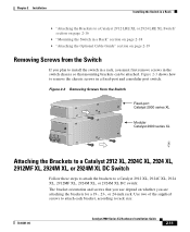
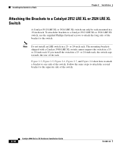
..."Attaching the Brackets to a Catalyst 2912 LRE XL or 2924 LRE XL Switch" section on page 2-16 • "Mounting the Switch in a Rack" section on page 2-18 • "Attaching the Optional Cable Guide" section on whether you are attaching the brackets for a 19-, 23-, or 24-inch rack. Use two of... the supplied screws to attach each bracket, according to install the switch in a rack, you must first remove screws in the switch chassis so that you use depend on page 2-19 Removing Screws from the Switch Catalyst 2900 SERIES XL Fixed-port Catalyst 2900 series XL Catalyst...
..."Attaching the Brackets to a Catalyst 2912 LRE XL or 2924 LRE XL Switch" section on page 2-16 • "Mounting the Switch in a Rack" section on page 2-18 • "Attaching the Optional Cable Guide" section on whether you are attaching the brackets for a 19-, 23-, or 24-inch rack. Use two of... the supplied screws to attach each bracket, according to install the switch in a rack, you must first remove screws in the switch chassis so that you use depend on page 2-19 Removing Screws from the Switch Catalyst 2900 SERIES XL Fixed-port Catalyst 2900 series XL Catalyst...
Hardware Installation Guide
Page 56
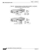
... 2924C XL, and 2924 XL Fixed-Port Switches (Front-Panel Forward) Phillips flat-head screws Phillips truss-head screws 19" configuration MODE 1X 2X 3X 4X 5X 6X 7X 47738 23" and 24" configuration MODE 1X 2X 3X 4X 5X 6X 7X 2-12 Catalyst 2900 Series XL Hardware Installation Guide 78-6461...-04 Installing the Switch in a Rack Chapter 2 Installation • For a 19-inch or a telco rack, use the...
... 2924C XL, and 2924 XL Fixed-Port Switches (Front-Panel Forward) Phillips flat-head screws Phillips truss-head screws 19" configuration MODE 1X 2X 3X 4X 5X 6X 7X 47738 23" and 24" configuration MODE 1X 2X 3X 4X 5X 6X 7X 2-12 Catalyst 2900 Series XL Hardware Installation Guide 78-6461...-04 Installing the Switch in a Rack Chapter 2 Installation • For a 19-inch or a telco rack, use the...
Hardware Installation Guide
Page 57
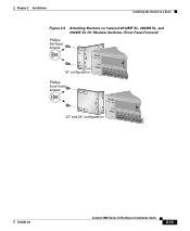
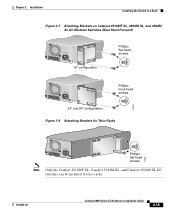
Chapter 2 Installation Installing the Switch in a Rack Figure 2-5 Attaching Brackets on Catalyst 2912MF XL, 2924M XL, and 2924M XL DC Modular Switches (Front-Panel Forward) Phillips flat-head screws 19" configuration Phillips truss-head screws 12 MODE 1X 2X 3X 4X 5X 6X 7X 23" and 24" configuration 12 MODE 1X 2X 3X 4X 5X 6X 7X 47297 78-6461-04 Catalyst 2900 Series XL Hardware Installation Guide 2-13
Chapter 2 Installation Installing the Switch in a Rack Figure 2-5 Attaching Brackets on Catalyst 2912MF XL, 2924M XL, and 2924M XL DC Modular Switches (Front-Panel Forward) Phillips flat-head screws 19" configuration Phillips truss-head screws 12 MODE 1X 2X 3X 4X 5X 6X 7X 23" and 24" configuration 12 MODE 1X 2X 3X 4X 5X 6X 7X 47297 78-6461-04 Catalyst 2900 Series XL Hardware Installation Guide 2-13
Hardware Installation Guide
Page 58
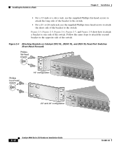
Installing the Switch in a Rack Chapter 2 Installation Figure 2-6 Attaching Brackets on Catalyst 2912 XL, 2924C XL, and 2924 XL Fixed-Port Switches (Rear-Panel Forward) 19" configuration Phillips flat-head screws 23" and 24" configuration Phillips truss-head screws 47298 2-14 Catalyst 2900 Series XL Hardware Installation Guide 78-6461-04
Installing the Switch in a Rack Chapter 2 Installation Figure 2-6 Attaching Brackets on Catalyst 2912 XL, 2924C XL, and 2924 XL Fixed-Port Switches (Rear-Panel Forward) 19" configuration Phillips flat-head screws 23" and 24" configuration Phillips truss-head screws 47298 2-14 Catalyst 2900 Series XL Hardware Installation Guide 78-6461-04
Hardware Installation Guide
Page 59
....0A0AT/2IN050G0--26400HVZ~ Phillips truss-head screws 23" and 24" configuration Figure 2-8 Attaching Brackets for Telco Racks 47299 DC INPUT 21.00A0-/11R2.0A0AT/2IN050G0--26400HVZ~ Phillips flat-head screws 71236 Note Only the Catalyst 2912MF XL, Catalyst 2924M XL, and Catalyst 2924M XL DC switches can be mounted in telco racks. 78-6461-04...
....0A0AT/2IN050G0--26400HVZ~ Phillips truss-head screws 23" and 24" configuration Figure 2-8 Attaching Brackets for Telco Racks 47299 DC INPUT 21.00A0-/11R2.0A0AT/2IN050G0--26400HVZ~ Phillips flat-head screws 71236 Note Only the Catalyst 2912MF XL, Catalyst 2924M XL, and Catalyst 2924M XL DC switches can be mounted in telco racks. 78-6461-04...
Hardware Installation Guide
Page 60
...long side of the rack. or 24-inch rack. The mounting brackets shipped with a Catalyst 2900 LRE XL switch cannot support the switch in a 23- Figure 2-3, Figure 2-5, Figure 2-6, Figure 2-7, and Figure 2-8 show how to attach a bracket to one side of the switch. 2-16 Catalyst 2900 Series XL Hardware Installation Guide... bracket to the switch. If you install the switch in a 19-inch rack. or 24-inch rack, the switch sags towards the rear of the bracket to the opposite side of the switch. To attach the brackets to a Catalyst 2912 LRE XL or 2924 LRE XL switch, use the supplied...
...long side of the rack. or 24-inch rack. The mounting brackets shipped with a Catalyst 2900 LRE XL switch cannot support the switch in a 23- Figure 2-3, Figure 2-5, Figure 2-6, Figure 2-7, and Figure 2-8 show how to attach a bracket to one side of the switch. 2-16 Catalyst 2900 Series XL Hardware Installation Guide... bracket to the switch. If you install the switch in a 19-inch rack. or 24-inch rack, the switch sags towards the rear of the bracket to the opposite side of the switch. To attach the brackets to a Catalyst 2912 LRE XL or 2924 LRE XL switch, use the supplied...
Hardware Installation Guide
Page 61
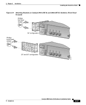
Chapter 2 Installation Installing the Switch in a Rack Figure 2-9 Attaching Brackets on Catalyst 2912 LRE XL and 2924 LRE XL Switches (Front-Panel Forward) Phillips flat-head screws Phillips truss-head screws 19" configuration INPUT OUTPUT PWR PWR RESET TEMP FAN 9X 10X 11X 12X 23" and 24" configuration INPUT OUTPUT PWR PWR RESET TEMP FAN 9X 10X 11X 12X 54728 78-6461-04 Catalyst 2900 Series XL Hardware Installation Guide 2-17
Chapter 2 Installation Installing the Switch in a Rack Figure 2-9 Attaching Brackets on Catalyst 2912 LRE XL and 2924 LRE XL Switches (Front-Panel Forward) Phillips flat-head screws Phillips truss-head screws 19" configuration INPUT OUTPUT PWR PWR RESET TEMP FAN 9X 10X 11X 12X 23" and 24" configuration INPUT OUTPUT PWR PWR RESET TEMP FAN 9X 10X 11X 12X 54728 78-6461-04 Catalyst 2900 Series XL Hardware Installation Guide 2-17
