Administration Guide
Page 2
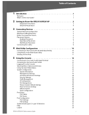
... 15 Using the Switch Main Menu 16 System Configuration 16 System Information 17 Management Settings 19 Username & Password Settings 24 Security Settings 25 VLAN Management 28 IP Configuration 29 File Management 43 Restore System ...Default Settings 46 Reset to Factory Settings 46 Reboot System 46 Stack Configuration 47 Port Status 47 Port Status 48 PoE Status 48 Port Configuration 49 Port Settings 49 PoE Settings 50 System Mode (Layer 2 / Layer 3) Selection 51 Help 52 Logout 53 SFE2010/SFE2010P Administration Guide...
... 15 Using the Switch Main Menu 16 System Configuration 16 System Information 17 Management Settings 19 Username & Password Settings 24 Security Settings 25 VLAN Management 28 IP Configuration 29 File Management 43 Restore System ...Default Settings 46 Reset to Factory Settings 46 Reboot System 46 Stack Configuration 47 Port Status 47 Port Status 48 PoE Status 48 Port Configuration 49 Port Settings 49 PoE Settings 50 System Mode (Layer 2 / Layer 3) Selection 51 Help 52 Logout 53 SFE2010/SFE2010P Administration Guide...
Administration Guide
Page 4
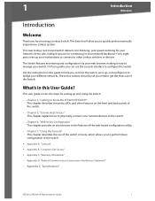
... D, "Federal Communication Commission Interference Statement" • Appendix E, "Specifications" SFE2010/SFE2010P Administration Guide 1 1 Introduction Welcome Introduction Welcome Thank you connect the switch, set it up, and configure it easy to manage your network backbone. Forty eight ports wire up and using the Switch. • Chapter 2, "Getting to Know the SFE2010/SFE2010P" This chapter describes the ports, LEDs, and...
... D, "Federal Communication Commission Interference Statement" • Appendix E, "Specifications" SFE2010/SFE2010P Administration Guide 1 1 Introduction Welcome Introduction Welcome Thank you connect the switch, set it up, and configure it easy to manage your network backbone. Forty eight ports wire up and using the Switch. • Chapter 2, "Getting to Know the SFE2010/SFE2010P" This chapter describes the ports, LEDs, and...

Administration Guide
Page 5
...its default settings. The Act (Activity) LEDs flash to indicate that this Switch is operating properly. On the SFE2010P, a green PoE LED indicates that port. SFE2010/SFE2010P Administration Guide 2 CAUTION: If the RESET switch is active on . All customized user settings will reset to its stack... ID. On the SFE2010, a green Speed LED indicates that the port is powered on ...
...its default settings. The Act (Activity) LEDs flash to indicate that this Switch is operating properly. On the SFE2010P, a green PoE LED indicates that port. SFE2010/SFE2010P Administration Guide 2 CAUTION: If the RESET switch is active on . All customized user settings will reset to its stack... ID. On the SFE2010, a green Speed LED indicates that the port is powered on ...
Administration Guide
Page 6
... 1000Mbps. Use the Linksys MGBT1, MGBSX1, or MGBLH1 mini-GBIC modules with an RJ-45 connector. NOTE: A switch is equipped with redundant power supply. The switch can operate in stacking mode by default. Each mini-GBIC port provides a link to a high-speed network segment...the device connected to Know the SFE2010/SFE2010P Feature 1-48 G1-G2 miniGBIC1/2 Description The Switch is in half and fullduplex modes. In stacking mode, ports G1 and G2 are Ethernet (802.3ab) uplink ports which use as stacking ports. SFE2010/SFE2010P Administration Guide 3 They can deliver a ...
... 1000Mbps. Use the Linksys MGBT1, MGBSX1, or MGBLH1 mini-GBIC modules with an RJ-45 connector. NOTE: A switch is equipped with redundant power supply. The switch can operate in stacking mode by default. Each mini-GBIC port provides a link to a high-speed network segment...the device connected to Know the SFE2010/SFE2010P Feature 1-48 G1-G2 miniGBIC1/2 Description The Switch is in half and fullduplex modes. In stacking mode, ports G1 and G2 are Ethernet (802.3ab) uplink ports which use as stacking ports. SFE2010/SFE2010P Administration Guide 3 They can deliver a ...
Administration Guide
Page 7
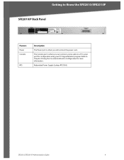
Getting to Chapter 4: Using the Console Interface for Configuration for configuration using your PC's HyperTerminal program. Refer to Know the SFE2010/SFE2010P SFE2010/P Back Panel Feature Power Console RPS Description The Power port is where you will connect the power cord. Redundant Power Supply (Linksys RPS1000) SFE2010/SFE2010P Administration Guide 4 The Console port is where you can connect a serial cable to a PC's serial port for more information.
Getting to Chapter 4: Using the Console Interface for Configuration for configuration using your PC's HyperTerminal program. Refer to Know the SFE2010/SFE2010P SFE2010/P Back Panel Feature Power Console RPS Description The Power port is where you will connect the power cord. Redundant Power Supply (Linksys RPS1000) SFE2010/SFE2010P Administration Guide 4 The Console port is where you can connect a serial cable to a PC's serial port for more information.
Administration Guide
Page 8
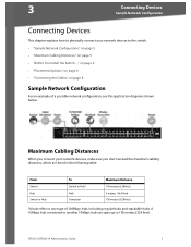
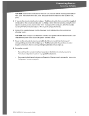
SFE2010/SFE2010P Administration Guide 5 3 Connecting Devices Sample Network Configuration Connecting Devices This chapter explains how to physically connect your network devices, make sure you connect your network devices to 100 meters (328 feet). A 10Mbps hub connected to another 10Mbps hub can span up to the switch. &#... Maximum Cabling Distances When you don't exceed the maximum cabling distances, which are listed in the following table: From Switch Hub Switch or Hub To Switch or Hub* Hub Computer Maximum Distance 100 meters (328 feet) 5 meters (16.4 feet) 100 meters (328 ...
SFE2010/SFE2010P Administration Guide 5 3 Connecting Devices Sample Network Configuration Connecting Devices This chapter explains how to physically connect your network devices, make sure you connect your network devices to 100 meters (328 feet). A 10Mbps hub connected to another 10Mbps hub can span up to the switch. &#... Maximum Cabling Distances When you don't exceed the maximum cabling distances, which are listed in the following table: From Switch Hub Switch or Hub To Switch or Hub* Hub Computer Maximum Distance 100 meters (328 feet) 5 meters (16.4 feet) 100 meters (328 ...
Administration Guide
Page 9
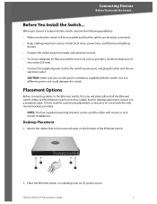
... it in a standard-sized, 19-inch wide for either wall mount or rack mount installations. Place the Ethernet switch on a wall with the switch. SFE2010/SFE2010P Administration Guide 6 Placement Options Before connecting cables to the Ethernet switch, first you use the power cord that the cables can be sure to provide a minimum clearance of the Ethernet...
... it in a standard-sized, 19-inch wide for either wall mount or rack mount installations. Place the Ethernet switch on a wall with the switch. SFE2010/SFE2010P Administration Guide 6 Placement Options Before connecting cables to the Ethernet switch, first you use the power cord that the cables can be sure to provide a minimum clearance of the Ethernet...
Administration Guide
Page 10
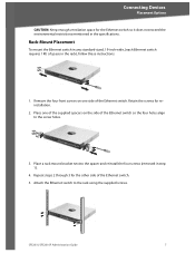
... 1). 4. Remove the four front screws on one of the supplied spacers on the side of space in the specifications. SFE2010/SFE2010P Administration Guide 7 Connecting Devices Placement Options CAUTION: Keep enough ventilation space for the Ethernet switch so it does not exceed the environmental restrictions mentioned in the rack), follow these instructions: 1. Place a rack mount...
... 1). 4. Remove the four front screws on one of the supplied spacers on the side of space in the specifications. SFE2010/SFE2010P Administration Guide 7 Connecting Devices Placement Options CAUTION: Keep enough ventilation space for the Ethernet switch so it does not exceed the environmental restrictions mentioned in the rack), follow these instructions: 1. Place a rack mount...

Administration Guide
Page 11
... to the screw holes. 3. Attach the Ethernet switch to a PC or other corners of the Ethernet switch. NOTE: If connecting an Ethernet switch to an SVR3000 router, connect it to the mini-GBIC port. SFE2010/SFE2010P Administration Guide 8 Place one of the uplink ports on the side of the Ethernet switch. 4. Connect the other end to a wall...
... to the screw holes. 3. Attach the Ethernet switch to a PC or other corners of the Ethernet switch. NOTE: If connecting an Ethernet switch to an SVR3000 router, connect it to the mini-GBIC port. SFE2010/SFE2010P Administration Guide 8 Place one of the uplink ports on the side of the Ethernet switch. 4. Connect the other end to a wall...
Administration Guide
Page 12
... the Web-based Utility to configure the Ethernet switch, proceed to your PC's serial port. (The PC must be running VT100 terminal emulation software, such as HyperTerminal.) 6. If a port has an active Gigabit connection, then its corresponding Gigabit LED will light up . 8. SFE2010/SFE2010P Administration Guide 9 Each active port's corresponding Act/Link LED will...
... the Web-based Utility to configure the Ethernet switch, proceed to your PC's serial port. (The PC must be running VT100 terminal emulation software, such as HyperTerminal.) 6. If a port has an active Gigabit connection, then its corresponding Gigabit LED will light up . 8. SFE2010/SFE2010P Administration Guide 9 Each active port's corresponding Act/Link LED will...
Administration Guide
Page 13
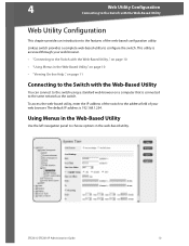
...your web browser. 4 Web Utility Configuration Connecting to the Switch with the Web-Based Utility You can connect to the switch using a standard web browser on a computer that is connected to the same network as the switch. SFE2010/SFE2010P Administration Guide 10 Using Menus in the Web-Based Utility Use the ...left navigation panel to choose options in the Web-Based Utility," on page 10 • "Viewing On-line Help ," on page 11 Connecting to the Switch with the Web-Based ...
...your web browser. 4 Web Utility Configuration Connecting to the Switch with the Web-Based Utility You can connect to the switch using a standard web browser on a computer that is connected to the same network as the switch. SFE2010/SFE2010P Administration Guide 10 Using Menus in the Web-Based Utility Use the ...left navigation panel to choose options in the Web-Based Utility," on page 10 • "Viewing On-line Help ," on page 11 Connecting to the Switch with the Web-Based ...
Administration Guide
Page 14
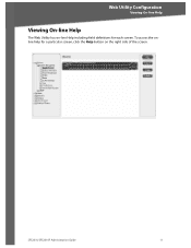
SFE2010/SFE2010P Administration Guide 11 Web Utility Configuration Viewing On-line Help Viewing On-line Help The Web Utility has on the right side of the screen. To access the online help for a particular screen, click the Help button on -line Help including field definitions for each screen.
SFE2010/SFE2010P Administration Guide 11 Web Utility Configuration Viewing On-line Help Viewing On-line Help The Web Utility has on the right side of the screen. To access the online help for a particular screen, click the Help button on -line Help including field definitions for each screen.
Administration Guide
Page 15
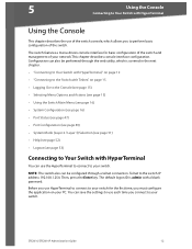
... can use the HyperTerminal to connect to your switch. The switch features a menu-driven console interface for the first time, you use HyperTerminal to connect to your switch for basic configuration of the switch and management of your network.This chapter describes console interface configuration. SFE2010/SFE2010P Administration Guide 12 Configuration can save the settings to use each...
... can use the HyperTerminal to connect to your switch. The switch features a menu-driven console interface for the first time, you use HyperTerminal to connect to your switch for basic configuration of the switch and management of your network.This chapter describes console interface configuration. SFE2010/SFE2010P Administration Guide 12 Configuration can save the settings to use each...
Administration Guide
Page 16
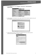
On the Connect To screen, use the Connect using drop-down list to select a port to Your Switch with the switch: COMn, or TCP/ IP. On the Connection Description screen, type a name for this connection, select an icon, and then click OK. 3. Using the Console Connecting to communicate with HyperTerminal 1. Click the Start button. Choose Programs > Accessories > Communications > HyperTerminal. 2. SFE2010/SFE2010P Administration Guide 13
On the Connect To screen, use the Connect using drop-down list to select a port to Your Switch with the switch: COMn, or TCP/ IP. On the Connection Description screen, type a name for this connection, select an icon, and then click OK. 3. Using the Console Connecting to communicate with HyperTerminal 1. Click the Start button. Choose Programs > Accessories > Communications > HyperTerminal. 2. SFE2010/SFE2010P Administration Guide 13
Administration Guide
Page 17
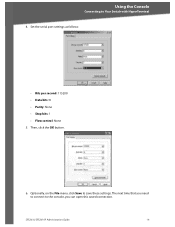
Using the Console Connecting to save these settings. Set the serial port settings as follows: • Bits per second: 115200 • Data bits: 8 • Parity: None • Stop bits: 1 • Flow control: None 5. SFE2010/SFE2010P Administration Guide 14 Optionally, on the File menu, click Save to Your Switch with HyperTerminal 4. The next time that you need to connect to the console, you can open this saved connection. Then, click the OK button. 6.
Using the Console Connecting to save these settings. Set the serial port settings as follows: • Bits per second: 115200 • Data bits: 8 • Parity: None • Stop bits: 1 • Flow control: None 5. SFE2010/SFE2010P Administration Guide 14 Optionally, on the File menu, click Save to Your Switch with HyperTerminal 4. The next time that you need to connect to the console, you can open this saved connection. Then, click the OK button. 6.
Administration Guide
Page 18
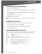
... keys Number key Tab Enter Esc Function Move the cursor up, down, left, or right. SFE2010/SFE2010P Administration Guide 15 NOTE: The Username & Password Settings screen can connect to the switch with telnet. 1. Actions appear at the end of the screen. Using the Console Connecting to ...the Switch with Telnet Connecting to the Switch with Telnet You can also be used to set passwords for...
... keys Number key Tab Enter Esc Function Move the cursor up, down, left, or right. SFE2010/SFE2010P Administration Guide 15 NOTE: The Username & Password Settings screen can connect to the switch with telnet. 1. Actions appear at the end of the screen. Using the Console Connecting to ...the Switch with Telnet Connecting to the Switch with Telnet You can also be used to set passwords for...
Administration Guide
Page 19
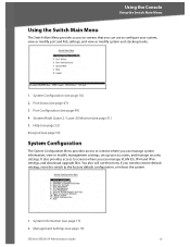
... settings. System Configuration (see page 51) 5. Port Configuration (see page 19) SFE2010/SFE2010P Administration Guide 16 Management Settings (see page 49) 4. Using the Console Using the Switch Main Menu Using the Switch Main Menu The Switch Main Menu provides access to screens that you can manage VLAN IDs, IPv4 and IPv6 settings, and download upgrade files. Help (see...
... settings. System Configuration (see page 51) 5. Port Configuration (see page 19) SFE2010/SFE2010P Administration Guide 16 Management Settings (see page 49) 4. Using the Console Using the Switch Main Menu Using the Switch Main Menu The Switch Main Menu provides access to screens that you can manage VLAN IDs, IPv4 and IPv6 settings, and download upgrade files. Help (see...
Administration Guide
Page 20
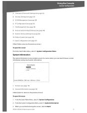
... Information The System Information menu provides access to Factory Settings (see page 29) 7. From the Switch Main Menu, select 1. System Configuration. 2. From the System Configuration Menu, select 1. SFE2010/SFE2010P Administration Guide 17 IP Configuration (see page 46) 10. VLAN Management (see page 25) 5. System Information. 3. General Information (see page 18) 0.Back (Select to return to...
... Information The System Information menu provides access to Factory Settings (see page 29) 7. From the Switch Main Menu, select 1. System Configuration. 2. From the System Configuration Menu, select 1. SFE2010/SFE2010P Administration Guide 17 IP Configuration (see page 46) 10. VLAN Management (see page 25) 5. System Information. 3. General Information (see page 18) 0.Back (Select to return to...
Administration Guide
Page 21
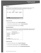
... Information Use the General System Information screen to display the boot, software, and hardware firmware versions of the Ethernet switch. SFE2010/SFE2010P Administration Guide 18 From the System Information Menu, select 2. To open this screen: 1. Versions. You also can enter a... system contact, system name, and system location. From the Switch Main Menu, select 1. System Information. 3. System Information. 3. To open this screen: 1....
... Information Use the General System Information screen to display the boot, software, and hardware firmware versions of the Ethernet switch. SFE2010/SFE2010P Administration Guide 18 From the System Information Menu, select 2. To open this screen: 1. Versions. You also can enter a... system contact, system name, and system location. From the Switch Main Menu, select 1. System Information. 3. System Information. 3. To open this screen: 1....
Administration Guide
Page 22
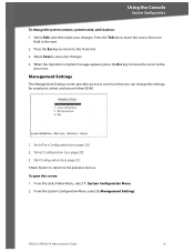
...SSH Configuration (see page 21) 0.Back (Select to return to the Action list. 3. Management Settings The Management Settings screen provides access to save your changes. Select Edit, and then make your changes. 4. From the...Management Settings. Press the Tab key to move the cursor to the next. 2. When the Operation complete message appears, press the Esc key to move the cursor from one field to the Action list. Telnet Configuration (see page 20) 2. System Configuration Menu. 2. From the Switch Main Menu, select 1. SFE2010/SFE2010P Administration Guide...
...SSH Configuration (see page 21) 0.Back (Select to return to the Action list. 3. Management Settings The Management Settings screen provides access to save your changes. Select Edit, and then make your changes. 4. From the...Management Settings. Press the Tab key to move the cursor to the next. 2. When the Operation complete message appears, press the Esc key to move the cursor from one field to the Action list. Telnet Configuration (see page 20) 2. System Configuration Menu. 2. From the Switch Main Menu, select 1. SFE2010/SFE2010P Administration Guide...