Installation Guide
Page 9
We assume that you might do something that could result in this manual. For more information, see the Cisco IOS documentation set from the Cisco IOS Software drop-down list. Caution Means reader be careful. Purpose This guide documents the hardware features of each switch, explains how to install a switch, and provides troubleshooting information...
We assume that you might do something that could result in this manual. For more information, see the Cisco IOS documentation set from the Cisco IOS Software drop-down list. Caution Means reader be careful. Purpose This guide documents the hardware features of each switch, explains how to install a switch, and provides troubleshooting information...
Installation Guide
Page 10
... this device. The EMC regulatory statements are also included in a situation that accompanied this product are translated into several languages in Cisco Product Documentation, which also lists all new and revised Cisco technical documentation, at the end of the hazards involved with electrical circuitry and be familiar with the product. These documents provide...
... this device. The EMC regulatory statements are also included in a situation that accompanied this product are translated into several languages in Cisco Product Documentation, which also lists all new and revised Cisco technical documentation, at the end of the hazards involved with electrical circuitry and be familiar with the product. These documents provide...
Installation Guide
Page 18
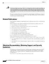
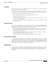
...Switch is incomplete. Switch is in initial setup, in initial setup. Switch failed to connect the management station. Front-Panel Description Figure 1-8 LEDs on the Cisco IEM-3000-8FM Module Chapter 1 Overview 201705 1 Setup LED 1 100BASE -FX port LEDs The Setup LED displays the express setup mode for the initial ... switch port to which to start initial setup or recovery because there is in recovery, or initial setup is configured as a managed switch. Table 1-2 lists the LED colors and their meanings. Cisco IE 3000 Switch Hardware Installation Guide 1-8 OL-13017-01
...Switch is incomplete. Switch is in initial setup, in initial setup. Switch failed to connect the management station. Front-Panel Description Figure 1-8 LEDs on the Cisco IEM-3000-8FM Module Chapter 1 Overview 201705 1 Setup LED 1 100BASE -FX port LEDs The Setup LED displays the express setup mode for the initial ... switch port to which to start initial setup or recovery because there is in recovery, or initial setup is configured as a managed switch. Table 1-2 lists the LED colors and their meanings. Cisco IE 3000 Switch Hardware Installation Guide 1-8 OL-13017-01

Installation Guide
Page 19
... red when power is green. If alarms are configured. Table 1-5 lists the power status LED colors and meanings. Power is not powered up. OL-13017-01 Cisco IE 3000 Switch Hardware Installation Guide 1-9 Alarm LED Table 1-4 lists the alarm LED colors and their meanings. If power is not powered... is not present; Table 1-3 System LED Color Off Green Red System Status System is not present, the LED color depends on . Table 1-3 lists the system LED colors and their meanings. Table 1-4 Alarm Status LED Color System Status Off Alarms are not configured, or the switch is off ...
... red when power is green. If alarms are configured. Table 1-5 lists the power status LED colors and meanings. Power is not powered up. OL-13017-01 Cisco IE 3000 Switch Hardware Installation Guide 1-9 Alarm LED Table 1-4 lists the alarm LED colors and their meanings. If power is not powered... is not present; Table 1-3 System LED Color Off Green Red System Status System is not present, the LED color depends on . Table 1-3 lists the system LED colors and their meanings. Table 1-4 Alarm Status LED Color System Status Off Alarms are not configured, or the switch is off ...
Installation Guide
Page 30
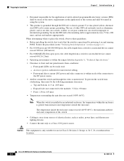
...FX fiber-optic ports, the cable length from a switch to an attached device cannot exceed 6562 ft (2 km). • Operating environment is within the ranges listed in Appendix A, "Technical Specifications." • Clearance to ports is sufficient for unrestricted cabling. - Front: 2.56 in . (105 mm) - Note When ...Follow the procedures in the "Verifying Switch Operation" section on ) that the switch is operational by powering it on and running POST. Cisco IE 3000 Switch Hardware Installation Guide 2-4 OL-13017-01 Use zinc-plated yellow-chromate steel DIN rail to assure proper grounding.
...FX fiber-optic ports, the cable length from a switch to an attached device cannot exceed 6562 ft (2 km). • Operating environment is within the ranges listed in Appendix A, "Technical Specifications." • Clearance to ports is sufficient for unrestricted cabling. - Front: 2.56 in . (105 mm) - Note When ...Follow the procedures in the "Verifying Switch Operation" section on ) that the switch is operational by powering it on and running POST. Cisco IE 3000 Switch Hardware Installation Guide 2-4 OL-13017-01 Use zinc-plated yellow-chromate steel DIN rail to assure proper grounding.
Installation Guide
Page 32
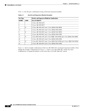
Adding Modules to the Switch Chapter 2 Switch Installation Table 2-1 lists the port combinations using switch and expansion modules. Cisco IE 3000 Switch Hardware Installation Guide 2-6 OL-13017-01 Even though the example configurations in Figure 2-1 show a Cisco IE-3000-4TC switch, the same combinations of the Cisco IE-3000-4TC switch and expansion modules. Table...
Adding Modules to the Switch Chapter 2 Switch Installation Table 2-1 lists the port combinations using switch and expansion modules. Cisco IE 3000 Switch Hardware Installation Guide 2-6 OL-13017-01 Even though the example configurations in Figure 2-1 show a Cisco IE-3000-4TC switch, the same combinations of the Cisco IE-3000-4TC switch and expansion modules. Table...
Installation Guide
Page 40
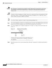
... Phillips head to remove the ground screw from the front panel of the switch. Store the ground screw for later use a UL-listed ring terminal lug suitable for number 10-to earth ground during normal use. Statement 1064 Caution To make sure that the switch functional ...ground lug is reliably connected to the external grounding screw. Use a wire-stripping tool to strip the 10-gauge wire to the wire. 2-14 Cisco IE 3000 Switch Hardware Installation Guide OL-13017-01 Figure 2-9 Stripping the Ground Wire 1 104908 2 3 1 0.5 in. (12.7 mm) ± 0.02 in. (0.5 mm)...
... Phillips head to remove the ground screw from the front panel of the switch. Store the ground screw for later use a UL-listed ring terminal lug suitable for number 10-to earth ground during normal use. Statement 1064 Caution To make sure that the switch functional ...ground lug is reliably connected to the external grounding screw. Use a wire-stripping tool to strip the 10-gauge wire to the wire. 2-14 Cisco IE 3000 Switch Hardware Installation Guide OL-13017-01 Figure 2-9 Stripping the Ground Wire 1 104908 2 3 1 0.5 in. (12.7 mm) ± 0.02 in. (0.5 mm)...

Installation Guide
Page 42
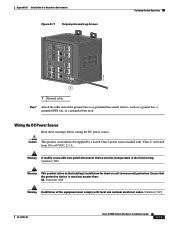
...on the building's installation for short-circuit (overcurrent) protection. Statement 1074 Warning Before performing any of the equipment must be supplied by a Listed Class 2 power source marked with local and national electrical codes. If the supply voltage is removed from the DC circuit. Statement 1022 Warning... This product relies on page 2-44. 2-16 Cisco IE 3000 Switch Hardware Installation Guide OL-13017-01 To wire the switch to the optional AC/DC converter, go to the "Connecting...
...on the building's installation for short-circuit (overcurrent) protection. Statement 1074 Warning Before performing any of the equipment must be supplied by a Listed Class 2 power source marked with local and national electrical codes. If the supply voltage is removed from the DC circuit. Statement 1022 Warning... This product relies on page 2-44. 2-16 Cisco IE 3000 Switch Hardware Installation Guide OL-13017-01 To wire the switch to the optional AC/DC converter, go to the "Connecting...
Installation Guide
Page 63
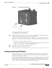
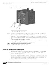
... into SFP module slots on . • There might not be of the same type as the SFP module on page C-5 for cable stipulations for the list of rugged SFP modules. If the port LED does not turn on: • The device at the other end might be a cable problem or a problem... the other end of the cable, and the cable must be turned on the front of the switch. OL-13017-01 Cisco IE 3000 Switch Hardware Installation Guide 2-37 See the Cisco IE 3000 release notes for SFP module connections. You can take up to cabling problems. Reconfigure and reboot the connected...
... into SFP module slots on . • There might not be of the same type as the SFP module on page C-5 for cable stipulations for the list of rugged SFP modules. If the port LED does not turn on: • The device at the other end might be a cable problem or a problem... the other end of the cable, and the cable must be turned on the front of the switch. OL-13017-01 Cisco IE 3000 Switch Hardware Installation Guide 2-37 See the Cisco IE 3000 release notes for SFP module connections. You can take up to cabling problems. Reconfigure and reboot the connected...
Installation Guide
Page 83
...• Verify that both sides have link. Verify that the module is supported on this platform. (The switch release notes on Cisco.com list the SFP modules that the switch supports.) • Use the show interfaces privileged EXEC command to verify the port or interface error... that the module meets the requirements for more information. • Rule out loose connections. Each Cisco module has an internal serial EEPROM that is not. OL-13017-01 Cisco IE 3000 Switch Hardware Installation Guide 3-3 Chapter 3 Troubleshooting Diagnosing Problems Link Status Verify that both ...
...• Verify that both sides have link. Verify that the module is supported on this platform. (The switch release notes on Cisco.com list the SFP modules that the switch supports.) • Use the show interfaces privileged EXEC command to verify the port or interface error... that the module meets the requirements for more information. • Rule out loose connections. Each Cisco module has an internal serial EEPROM that is not. OL-13017-01 Cisco IE 3000 Switch Hardware Installation Guide 3-3 Chapter 3 Troubleshooting Diagnosing Problems Link Status Verify that both ...
Installation Guide
Page 87
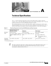
...The safety certifications apply only to 60°C) temperature 1. A A P P E N D I X Technical Specifications Table A-1 lists the operating temperatures for the Cisco IE 3000 Switches and Power Convertor Enclosure types Industrial Automation and Hazardous Locations Substation Sealed enclosures Vented enclosures For example: NEMA4, NEMA4X,... For example: NEMA1, IP20, and NEMA12, NEMA13, IP54, and IP21. Table A-3 lists the technical specifications for the Cisco IE 3000 switches, modules, and the power convertor varies among environments, based on factors such as the system...
...The safety certifications apply only to 60°C) temperature 1. A A P P E N D I X Technical Specifications Table A-1 lists the operating temperatures for the Cisco IE 3000 Switches and Power Convertor Enclosure types Industrial Automation and Hazardous Locations Substation Sealed enclosures Vented enclosures For example: NEMA4, NEMA4X,... For example: NEMA1, IP20, and NEMA12, NEMA13, IP54, and IP21. Table A-3 lists the technical specifications for the Cisco IE 3000 switches, modules, and the power convertor varies among environments, based on factors such as the system...
Installation Guide
Page 96
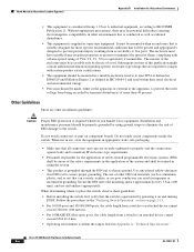
... conducted as well as open-type equipment. Do not touch connectors or pins on and running POST. Cisco IE 3000 Switch Hardware Installation Guide B-6 OL-13017-01 The enclosure must have suitable flame-retardant properties ...spread of this publication might contain additional information regarding specific enclosure-type ratings that is required whenever you handle Cisco equipment. Secure the DIN rail to the mounting surface approximately every 7.8 in. (200 mm), and use ...packaging. • Make sure that will be mounted within the ranges listed in the application of a tool.
... conducted as well as open-type equipment. Do not touch connectors or pins on and running POST. Cisco IE 3000 Switch Hardware Installation Guide B-6 OL-13017-01 The enclosure must have suitable flame-retardant properties ...spread of this publication might contain additional information regarding specific enclosure-type ratings that is required whenever you handle Cisco equipment. Secure the DIN rail to the mounting surface approximately every 7.8 in. (200 mm), and use ...packaging. • Make sure that will be mounted within the ranges listed in the application of a tool.
Installation Guide
Page 99
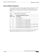
... In a Hazardous Environment Adding Modules to the switch. Table B-1 lists the port combinations using switch and expansion modules. If you are installing two modules, the first must be a Cisco IEM-3000-8TM, and the second can be either a Cisco IEM-3000-8TM or a Cisco IEM-3000-8FM. Even though the example configurations in Figure...
... In a Hazardous Environment Adding Modules to the switch. Table B-1 lists the port combinations using switch and expansion modules. If you are installing two modules, the first must be a Cisco IEM-3000-8TM, and the second can be either a Cisco IEM-3000-8TM or a Cisco IEM-3000-8FM. Even though the example configurations in Figure...
Installation Guide
Page 107
... or 1569 twisted-pair copper appliance wiring material (AWM) wire (such as Belden part number 9912 or equivalent) • For DC power connections, use a UL-listed ring terminal lug suitable for number 10-to earth ground by using the ground screw, follow any grounding requirements at least a 4mm2 conductor to connect...
... or 1569 twisted-pair copper appliance wiring material (AWM) wire (such as Belden part number 9912 or equivalent) • For DC power connections, use a UL-listed ring terminal lug suitable for number 10-to earth ground by using the ground screw, follow any grounding requirements at least a 4mm2 conductor to connect...
Installation Guide
Page 109
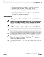
...'s installation for short-circuit (overcurrent) protection. Ensure that the protective device is intended to be incorporated in the fixed wiring. Statement 1074 OL-13017-01 Cisco IE 3000 Switch Hardware Installation Guide B-19 Warning A readily accessible two-poled disconnect device must comply with "Class 2" and rated from 18 to a grounded ... Figure B-11 Torquing Ground-Lug Screws Verifying Switch Operation 201696 1 1 Ground cable Step 7 Attach the other end of the equipment must be supplied by a Listed Class 2 power source marked with local and national electrical codes.
...'s installation for short-circuit (overcurrent) protection. Ensure that the protective device is intended to be incorporated in the fixed wiring. Statement 1074 OL-13017-01 Cisco IE 3000 Switch Hardware Installation Guide B-19 Warning A readily accessible two-poled disconnect device must comply with "Class 2" and rated from 18 to a grounded ... Figure B-11 Torquing Ground-Lug Screws Verifying Switch Operation 201696 1 1 Ground cable Step 7 Attach the other end of the equipment must be supplied by a Listed Class 2 power source marked with local and national electrical codes.
Installation Guide
Page 132
... device. See Chapter 3, "Troubleshooting," for solutions to connect each device. See the Cisco IE 3000 release notes for reliable communications. Each SFP module must not exceed the stipulated cable length for the list of the switch. Repeat Steps 1 through 3 to cabling problems. Reconfigure and reboot ... receive (RX). This can use any combination of rugged SFP modules. You can take up to install and remove SFP modules. B-42 Cisco IE 3000 Switch Hardware Installation Guide OL-13017-01 See Table C-1 on page C-5 for cable stipulations for loops. The port LED is ...
... device. See Chapter 3, "Troubleshooting," for solutions to connect each device. See the Cisco IE 3000 release notes for reliable communications. Each SFP module must not exceed the stipulated cable length for the list of the switch. Repeat Steps 1 through 3 to cabling problems. Reconfigure and reboot ... receive (RX). This can use any combination of rugged SFP modules. You can take up to install and remove SFP modules. B-42 Cisco IE 3000 Switch Hardware Installation Guide OL-13017-01 See Table C-1 on page C-5 for cable stipulations for loops. The port LED is ...

Installation Guide
Page 153
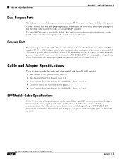
... emitted from disconnected fibers or connectors. Figure C-4 Pin 1 2 3 4 5 6 7 8 Copper SFP Module RJ-45 Connector Label 12345678 TP0+ TP0TP1+ TP2+ TP2TP1TP3+ TP3- 60915 OL-13017-01 Cisco IE 3000 Switch Hardware Installation Guide C-3 or 62.5/125-micron multimode fiber-optic cabling. SFP Module Ports The switch uses SFP modules for fiber-optic...
... emitted from disconnected fibers or connectors. Figure C-4 Pin 1 2 3 4 5 6 7 8 Copper SFP Module RJ-45 Connector Label 12345678 TP0+ TP0TP1+ TP2+ TP2TP1TP3+ TP3- 60915 OL-13017-01 Cisco IE 3000 Switch Hardware Installation Guide C-3 or 62.5/125-micron multimode fiber-optic cabling. SFP Module Ports The switch uses SFP modules for fiber-optic...
Installation Guide
Page 154
... connections. Copper 1000BASE-T SFP transceivers use standard four twisted-pair, Category 5 or greater cable at lengths up to a terminal. Cisco IE 3000 Switch Hardware Installation Guide C-4 OL-13017-01 Each port must not exceed the required cable length. Figure C-2 shows the... The auto-MDIX feature is enabled by default. For configuration information for a list of supported SFP modules. You can order a kit (part number ACS-DSBUASYN=) containing that adapter from Cisco. Cable and Adapter Specifications Appendix C Cable and Connectors Dual-Purpose Ports The Ethernet...
... connections. Copper 1000BASE-T SFP transceivers use standard four twisted-pair, Category 5 or greater cable at lengths up to a terminal. Cisco IE 3000 Switch Hardware Installation Guide C-4 OL-13017-01 Each port must not exceed the required cable length. Figure C-2 shows the... The auto-MDIX feature is enabled by default. For configuration information for a list of supported SFP modules. You can order a kit (part number ACS-DSBUASYN=) containing that adapter from Cisco. Cable and Adapter Specifications Appendix C Cable and Connectors Dual-Purpose Ports The Ethernet...

Installation Guide
Page 158
... Console Port (DTE) Signal RTS DTR TxD GND GND RxD DSR CTS RJ-45-to -DB-9 adapter cable, and the console device. Adapter Pinouts Table C-2 lists the pinouts for 10/100/1000 and 1000BASE-T SFP Module Ports Switch 1 TP0+ 2 TP03 TP1+ 6 TP1- 4 TP2+ 5 TP27 TP3+ 8 TP3- Cable and Adapter Specifications Appendix... Schematics for the console port, the RJ-45-to -DB-9 Terminal Adapter DB-9 Pin 8 6 2 5 5 3 4 7 Console Device Signal CTS DSR RxD GND GND TxD DTR RTS Cisco IE 3000 Switch Hardware Installation Guide C-8 OL-13017-01
... Console Port (DTE) Signal RTS DTR TxD GND GND RxD DSR CTS RJ-45-to -DB-9 adapter cable, and the console device. Adapter Pinouts Table C-2 lists the pinouts for 10/100/1000 and 1000BASE-T SFP Module Ports Switch 1 TP0+ 2 TP03 TP1+ 6 TP1- 4 TP2+ 5 TP27 TP3+ 8 TP3- Cable and Adapter Specifications Appendix... Schematics for the console port, the RJ-45-to -DB-9 Terminal Adapter DB-9 Pin 8 6 2 5 5 3 4 7 Console Device Signal CTS DSR RxD GND GND TxD DTR RTS Cisco IE 3000 Switch Hardware Installation Guide C-8 OL-13017-01

Installation Guide
Page 159
Appendix C Cable and Connectors Cable and Adapter Specifications Table C-3 lists the pinouts for the console port, RJ-45-to -DB-25 Terminal Adapter DB-25 Pin 5 6 3 7 7 2 20 4 Console Device Signal CTS DSR RxD GND GND TxD DTR RTS OL-13017-01 Cisco IE 3000 Switch Hardware Installation Guide C-9 Table C-3 Console Port Signaling Using... CTS RJ-45-to -DB-25 female DTE adapter, and the console device. You can order a kit (part number ACS-DSBUASYN=) containing this adapter from Cisco. Note The RJ-45-to-DB-25 female DTE adapter is not supplied with the switch.
Appendix C Cable and Connectors Cable and Adapter Specifications Table C-3 lists the pinouts for the console port, RJ-45-to -DB-25 Terminal Adapter DB-25 Pin 5 6 3 7 7 2 20 4 Console Device Signal CTS DSR RxD GND GND TxD DTR RTS OL-13017-01 Cisco IE 3000 Switch Hardware Installation Guide C-9 Table C-3 Console Port Signaling Using... CTS RJ-45-to -DB-25 female DTE adapter, and the console device. You can order a kit (part number ACS-DSBUASYN=) containing this adapter from Cisco. Note The RJ-45-to-DB-25 female DTE adapter is not supplied with the switch.