
Installation Guide
Page 3
... x Overview 1-1 Overview 1-1 Switch Models 1-2 Front-Panel Description 1-2 10/100 Ports 1-5 Dual-Purpose Ports 1-5 100BASE-FX Ports 1-5 Power and Relay Connector 1-5 Console Port 1-6 LEDs 1-6 Setup LED 1-8 System LED 1-9 Alarm LED 1-9 Power Status LED 1-9 10/100 Port Status LEDs 1-10 100Base-FX Port Status LEDs 1-10 Dual-Purpose Port LEDs 1-11... Memory Card 1-11 Rear-Panel Description 1-12 Power Converter (Optional) 1-13 Management Options 1-14 Network Configurations 1-15 Switch Installation 2-1 Preparing for Installation 2-1 Warnings 2-2 Cisco IE 3000 Switch Hardware Installation Guide iii
... x Overview 1-1 Overview 1-1 Switch Models 1-2 Front-Panel Description 1-2 10/100 Ports 1-5 Dual-Purpose Ports 1-5 100BASE-FX Ports 1-5 Power and Relay Connector 1-5 Console Port 1-6 LEDs 1-6 Setup LED 1-8 System LED 1-9 Alarm LED 1-9 Power Status LED 1-9 10/100 Port Status LEDs 1-10 100Base-FX Port Status LEDs 1-10 Dual-Purpose Port LEDs 1-11... Memory Card 1-11 Rear-Panel Description 1-12 Power Converter (Optional) 1-13 Management Options 1-14 Network Configurations 1-15 Switch Installation 2-1 Preparing for Installation 2-1 Warnings 2-2 Cisco IE 3000 Switch Hardware Installation Guide iii
Installation Guide
Page 7
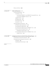
... C-6 Crossover Cable and Adapter Pinouts C-7 Identifying a Crossover Cable C-7 Four Twisted-Pair Cable Pinouts for 1000BASE-T Ports C-7 Adapter Pinouts C-8 Configuring the Switch with the CLI-Based Setup Program D-1 Accessing the CLI from the Console Port D-1 Entering the Initial Configuration Information D-2 IP Settings D-2 Completing the...
... C-6 Crossover Cable and Adapter Pinouts C-7 Identifying a Crossover Cable C-7 Four Twisted-Pair Cable Pinouts for 1000BASE-T Ports C-7 Adapter Pinouts C-8 Configuring the Switch with the CLI-Based Setup Program D-1 Accessing the CLI from the Console Port D-1 Entering the Initial Configuration Information D-2 IP Settings D-2 Completing the...
Installation Guide
Page 17
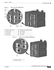
Chapter 1 Overview Figure 1-6 1 2 3 4 LEDs on the Cisco IE 3000 Switch Front-Panel Description 201703 5 67 8 1 Express setup button 2 System LED 3 Alarm LED 4 Setup LED 5 Dual-purpose uplink port LED 6 Pwr B LED 7 Pwr A LED 8 Port LED Figure 1-7 LEDs on the Cisco IEM-3000-8TM Module 201706 1 1 10/100 port LED OL-13017-01 Cisco IE 3000 Switch Hardware Installation Guide 1-7
Chapter 1 Overview Figure 1-6 1 2 3 4 LEDs on the Cisco IE 3000 Switch Front-Panel Description 201703 5 67 8 1 Express setup button 2 System LED 3 Alarm LED 4 Setup LED 5 Dual-purpose uplink port LED 6 Pwr B LED 7 Pwr A LED 8 Port LED Figure 1-7 LEDs on the Cisco IEM-3000-8TM Module 201706 1 1 10/100 port LED OL-13017-01 Cisco IE 3000 Switch Hardware Installation Guide 1-7
Installation Guide
Page 18
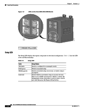
.... Disconnect a device from a switch port, and then press the Express Setup button. Switch is in initial setup, in initial setup. Table 1-2 lists the LED colors and their meanings. Table 1-2 Setup LED Color Off (dark) Solid green Blinking green Solid red Setup Status Switch is incomplete. Cisco IE 3000 Switch Hardware Installation Guide 1-8 OL-13017-01 Front...
.... Disconnect a device from a switch port, and then press the Express Setup button. Switch is in initial setup, in initial setup. Table 1-2 lists the LED colors and their meanings. Table 1-2 Setup LED Color Off (dark) Solid green Blinking green Solid red Setup Status Switch is incomplete. Cisco IE 3000 Switch Hardware Installation Guide 1-8 OL-13017-01 Front...
Installation Guide
Page 48
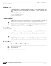
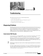
...Results When you want to the switch. One at a time, the System, Alarm, Setup, Pwr A, and Pwr B LEDs each LED is connected to a power converter, see ...that verify that the switch functions properly and ensures that is tested. All LEDs are usually fatal. Call Cisco Systems immediately if your switch does not pass POST. Decide where you power on the switch, it automatically.... The POST runs a series of the processing and memory hardware. The System LED blinks green as the Cisco IOS software image loads. Assuming all tests pass, the System LED continues to install. Note POST failures are...
...Results When you want to the switch. One at a time, the System, Alarm, Setup, Pwr A, and Pwr B LEDs each LED is connected to a power converter, see ...that verify that the switch functions properly and ensures that is tested. All LEDs are usually fatal. Call Cisco Systems immediately if your switch does not pass POST. Decide where you power on the switch, it automatically.... The POST runs a series of the processing and memory hardware. The System LED blinks green as the Cisco IOS software image loads. Assuming all tests pass, the System LED continues to install. Note POST failures are...
Installation Guide
Page 72
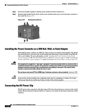
... a switch module. It must be accessible only by the use the alarm connections on that connector. 2-46 Cisco IE 3000 Switch Hardware Installation Guide OL-13017-01 The enclosure must be a minimum of 3 inches (76....assembly. WARNING Tpeploohewwicseetrurrinccciotosrmrhddois.gchbkTteohfdoairrsveecedosumnecnroevericecthtintehtghareunisnkotitwn.oeof Pwr B (24VDC or 48 VDC) 1 Rtn B 6 Minor Alarm 2 Express Setup System Pwr A Alarm Pwr B 7 Setup 1 3 8 2 4 Cisco Catalyst Installing the Power Converter on a DIN Rail, Wall, or Rack Adapter You install the power converter on ...
... a switch module. It must be accessible only by the use the alarm connections on that connector. 2-46 Cisco IE 3000 Switch Hardware Installation Guide OL-13017-01 The enclosure must be a minimum of 3 inches (76....assembly. WARNING Tpeploohewwicseetrurrinccciotosrmrhddois.gchbkTteohfdoairrsveecedosumnecnroevericecthtintehtghareunisnkotitwn.oeof Pwr B (24VDC or 48 VDC) 1 Rtn B 6 Minor Alarm 2 Express Setup System Pwr A Alarm Pwr B 7 Setup 1 3 8 2 4 Cisco Catalyst Installing the Power Converter on a DIN Rail, Wall, or Rack Adapter You install the power converter on ...
Installation Guide
Page 81
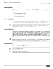
...a series of tests that runs automatically to ensure that cycles once through the System, Alarm, Setup, Pwr A, and Pwr B LEDs. Note POST failures are usually fatal. Contact your Cisco technical support representative if your IE2100 or SNMP application for the switch to 9600 bits per second... your switch does not pass POST. If you can also get statistics from the browser interface, the command-line interface (CLI), the Cisco Intelligence Engine 2100 (IE2100) Series Configuration Registrar, or a Simple Network Management Protocol (SNMP) workstation. For more information about the switch....
...a series of tests that runs automatically to ensure that cycles once through the System, Alarm, Setup, Pwr A, and Pwr B LEDs. Note POST failures are usually fatal. Contact your Cisco technical support representative if your IE2100 or SNMP application for the switch to 9600 bits per second... your switch does not pass POST. If you can also get statistics from the browser interface, the command-line interface (CLI), the Cisco Intelligence Engine 2100 (IE2100) Series Configuration Registrar, or a Simple Network Management Protocol (SNMP) workstation. For more information about the switch....
Installation Guide
Page 85
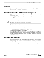
Caution Resetting the switch deletes the configuration and reboots the switch. Release the Express Setup button, and the switch continues to the factory default settings. OL-13017-01 Cisco IE 3000 Switch Hardware Installation Guide 3-5 How to Clear the Switch IP Address and Configuration Follow... recovery is to recover from a lost or forgotten password is a feature that a system administrator can configure the switch by using Express Setup as described in Appendix D, "Configuring the Switch with the switch. To reset the password on the switch: 1. After the switch restarts...
Caution Resetting the switch deletes the configuration and reboots the switch. Release the Express Setup button, and the switch continues to the factory default settings. OL-13017-01 Cisco IE 3000 Switch Hardware Installation Guide 3-5 How to Clear the Switch IP Address and Configuration Follow... recovery is to recover from a lost or forgotten password is a feature that a system administrator can configure the switch by using Express Setup as described in Appendix D, "Configuring the Switch with the switch. To reset the password on the switch: 1. After the switch restarts...
Installation Guide
Page 115
...page B-25 Power On the Switch To apply power to the Power Converter" section on page B-59. One at a time, the System, Alarm, Setup, Pwr A, and Pwr B LEDs each LED is directly connected to the ON position. Step 1 Step 2 Step 3 Turn off . Disconnect the cables...x. See the "Obtaining Documentation, Obtaining Support, and Security Guidelines" section on the panel board that it automatically initiates a POST. Call Cisco Systems immediately if your switch does not pass POST. Disconnect Power After successfully running POST, follow these steps. All LEDs are usually fatal....
...page B-25 Power On the Switch To apply power to the Power Converter" section on page B-59. One at a time, the System, Alarm, Setup, Pwr A, and Pwr B LEDs each LED is directly connected to the ON position. Step 1 Step 2 Step 3 Turn off . Disconnect the cables...x. See the "Obtaining Documentation, Obtaining Support, and Security Guidelines" section on the panel board that it automatically initiates a POST. Call Cisco Systems immediately if your switch does not pass POST. Disconnect Power After successfully running POST, follow these steps. All LEDs are usually fatal....
Installation Guide
Page 141
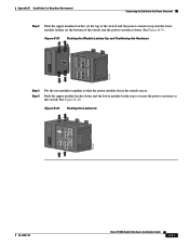
... Pwr A (24VDC or 48 VDC) Rtn A Major Alarm 5 ! WARNING Tpeploohewwicseetrurrinccciotosrmrhddois.gchbkTteohfdoairrsveecedosumnecnroevericecthtintehtghareunisnkotitwn.oeof Pwr B (24VDC or 48 VDC) 1 Rtn B 6 Minor Alarm 2 Express Setup System Pwr A Alarm Pwr B 7 Setup 1 3 8 2 4 Cisco Catalyst OL-13017-01 Cisco IE 3000 Switch Hardware Installation Guide B-51 Push the upper module latches down . Figure B-39 Pushing the Module Latches Up and...
... Pwr A (24VDC or 48 VDC) Rtn A Major Alarm 5 ! WARNING Tpeploohewwicseetrurrinccciotosrmrhddois.gchbkTteohfdoairrsveecedosumnecnroevericecthtintehtghareunisnkotitwn.oeof Pwr B (24VDC or 48 VDC) 1 Rtn B 6 Minor Alarm 2 Express Setup System Pwr A Alarm Pwr B 7 Setup 1 3 8 2 4 Cisco Catalyst OL-13017-01 Cisco IE 3000 Switch Hardware Installation Guide B-51 Push the upper module latches down . Figure B-39 Pushing the Module Latches Up and...
Installation Guide
Page 161
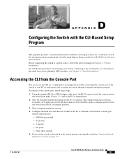
... I X Configuring the Switch with the CLI-Based Setup Program This appendix provides a command-line interface (CLI)-based setup procedure for mounting your switch, connecting to the switch ports, or connecting to the small form-factor pluggable (SFP) modules, see the Cisco IE 3000 Switch Getting Started Guide. OL-13017-01... Cisco IE 3000 Switch Hardware ...
... I X Configuring the Switch with the CLI-Based Setup Program This appendix provides a command-line interface (CLI)-based setup procedure for mounting your switch, connecting to the switch ports, or connecting to the small form-factor pluggable (SFP) modules, see the Cisco IE 3000 Switch Getting Started Guide. OL-13017-01... Cisco IE 3000 Switch Hardware ...

Installation Guide
Page 162
... configuration dialog? [yes/no ]: yes Step 2 Enter a hostname for any switch. Enter host name [Switch]: host_name Cisco IE 3000 Switch Hardware Installation Guide D-2 OL-13017-01 Follow the steps described in square brackets '[]'. Basic management setup configures only enough connectivity for help. Entering the Initial Configuration Information Appendix D Configuring the Switch with...
... configuration dialog? [yes/no ]: yes Step 2 Enter a hostname for any switch. Enter host name [Switch]: host_name Cisco IE 3000 Switch Hardware Installation Guide D-2 OL-13017-01 Follow the steps described in square brackets '[]'. Basic management setup configures only enough connectivity for help. Entering the Initial Configuration Information Appendix D Configuring the Switch with...
Installation Guide
Page 163
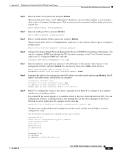
... no snmp-server ! ! You can configure the switch as a command switch later through the CLI, the device manager, or the Cisco Network Assistant application. For this interface [255.0.0.0]: 255.0.0.0 Step 9 Enter Y to the management network, and press Return. If you like...enable password: enable_password Step 5 Enter a virtual terminal (Telnet) password, and press Return. The password can start with the CLI-Based Setup Program Entering the Initial Configuration Information Step 3 Enter an enable secret password, and press Return. To configure SNMP later, enter no ....
... no snmp-server ! ! You can configure the switch as a command switch later through the CLI, the device manager, or the Cisco Network Assistant application. For this interface [255.0.0.0]: 255.0.0.0 Step 9 Enter Y to the management network, and press Return. If you like...enable password: enable_password Step 5 Enter a virtual terminal (Telnet) password, and press Return. The password can start with the CLI-Based Setup Program Entering the Initial Configuration Information Step 3 Enter an enable secret password, and press Return. To configure SNMP later, enter no ....
Installation Guide
Page 164
...next time the switch reboots, save it in NVRAM by using a terminal emulation program or through the network by selecting option 2. Cisco IE 3000 Switch Hardware Installation Guide D-4 OL-13017-01 If you want to nvram and exit. For configuration information, see the ...Getting Started with the CLI-Based Setup Program interface FastEthernet1/1 ! interface FastEthernet1/2 ! Enter your selection [2]:2 Make your selection, and press Return. To use the CLI, enter commands...
...next time the switch reboots, save it in NVRAM by using a terminal emulation program or through the network by selecting option 2. Cisco IE 3000 Switch Hardware Installation Guide D-4 OL-13017-01 If you want to nvram and exit. For configuration information, see the ...Getting Started with the CLI-Based Setup Program interface FastEthernet1/1 ! interface FastEthernet1/2 ! Enter your selection [2]:2 Make your selection, and press Return. To use the CLI, enter commands...
Installation Guide
Page 167
... B-40 J jewelry removal warning 2-2, B-2 L LEDs 100BASE-FX ports 1-10 alarm 1-9 dual-purpose port 1-11 front panel 1-6 to 1-11 port status 1-10 POST results 3-1 power status 1-9 setup 1-8 system 1-9 troubleshooting with 3-2 lightning activity warning 2-2, B-2 link status troubleshooting 3-3 M management options 1-14 to 1-15 module configurations 2-6, B-9 connecting 2-8, B-11 mounting rack 2-29 to 2-31, B-33 to...
... B-40 J jewelry removal warning 2-2, B-2 L LEDs 100BASE-FX ports 1-10 alarm 1-9 dual-purpose port 1-11 front panel 1-6 to 1-11 port status 1-10 POST results 3-1 power status 1-9 setup 1-8 system 1-9 troubleshooting with 3-2 lightning activity warning 2-2, B-2 link status troubleshooting 3-3 M management options 1-14 to 1-15 module configurations 2-6, B-9 connecting 2-8, B-11 mounting rack 2-29 to 2-31, B-33 to...


