Installation Guide
Page 2
... THE INFORMATION PACKET THAT SHIPPED WITH THE PRODUCT AND ARE INCORPORATED HEREIN BY THIS REFERENCE. These specifications are designed to correct the interference by the Cisco equipment or one side or the other countries. If the equipment causes interference to radio or television... in the equipment no guarantee that event, your own expense. The use of Cisco Systems, Inc. This equipment generates, uses, and can determine whether your authority to comply with the specifications in a residential installation. This equipment has been tested and found to operate the...
... THE INFORMATION PACKET THAT SHIPPED WITH THE PRODUCT AND ARE INCORPORATED HEREIN BY THIS REFERENCE. These specifications are designed to correct the interference by the Cisco equipment or one side or the other countries. If the equipment causes interference to radio or television... in the equipment no guarantee that event, your own expense. The use of Cisco Systems, Inc. This equipment generates, uses, and can determine whether your authority to comply with the specifications in a residential installation. This equipment has been tested and found to operate the...

Installation Guide
Page 5
... Autonegotiation 3-4 Autonegotiation and NIC 3-4 Cabling Distance 3-5 How to Clear the Switch IP Address and Configuration 3-5 How to Recover Passwords 3-5 Finding the Switch Serial Number 3-6 Technical Specifications A-1 Installation In a Hazardous Environment B-1 Preparing for Installation B-1 Warnings B-2 North American Hazardous Location Approval B-5 EMC Environmental Conditions for Products Installed in the European Union B-5 Installation Guidelines...
... Autonegotiation 3-4 Autonegotiation and NIC 3-4 Cabling Distance 3-5 How to Clear the Switch IP Address and Configuration 3-5 How to Recover Passwords 3-5 Finding the Switch Serial Number 3-6 Technical Specifications A-1 Installation In a Hazardous Environment B-1 Preparing for Installation B-1 Warnings B-2 North American Hazardous Location Approval B-5 EMC Environmental Conditions for Products Installed in the European Union B-5 Installation Guidelines...
Installation Guide
Page 7
...C-1 Connecting to 1000BASE-T Devices C-1 100BASE-FX Ports C-3 SFP Module Ports C-3 Dual-Purpose Ports C-4 Console Port C-4 Cable and Adapter Specifications C-4 SFP Module Cable Specifications C-4 Two Twisted-Pair Cable Pinouts C-5 Four Twisted-Pair Cable Pinouts for 1000BASE-T Ports C-6 Crossover Cable and Adapter Pinouts C-7 Identifying a ...Console Port D-1 Entering the Initial Configuration Information D-2 IP Settings D-2 Completing the Setup Program D-2 Contents OL-13017-01 Cisco IE 3000 Switch Hardware Installation Guide vii and 100BASE-TX-Compatible Devices C-1 Connecting to 10BASE-T-
...C-1 Connecting to 1000BASE-T Devices C-1 100BASE-FX Ports C-3 SFP Module Ports C-3 Dual-Purpose Ports C-4 Console Port C-4 Cable and Adapter Specifications C-4 SFP Module Cable Specifications C-4 Two Twisted-Pair Cable Pinouts C-5 Four Twisted-Pair Cable Pinouts for 1000BASE-T Ports C-6 Crossover Cable and Adapter Pinouts C-7 Identifying a ...Console Port D-1 Entering the Initial Configuration Information D-2 IP Settings D-2 Completing the Setup Program D-2 Contents OL-13017-01 Cisco IE 3000 Switch Hardware Installation Guide vii and 100BASE-TX-Compatible Devices C-1 Connecting to 10BASE-T-
Installation Guide
Page 29
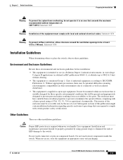
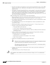
... installation guidelines: Caution Proper ESD protection is supplied as radiated disturbance. • This equipment is required whenever you handle Cisco equipment. Subsequent sections of flame, complying with certain product safety certifications. Installation and maintenance personnel should be at altitudes up... to 9842 ft (3 km) without derating. • This equipment is suitably designed for those specific environmental conditions that exceeds the maximum recommended ambient temperature of: 140°F (60°C) Statement 1047 Warning Installation of ...
... installation guidelines: Caution Proper ESD protection is supplied as radiated disturbance. • This equipment is required whenever you handle Cisco equipment. Subsequent sections of flame, complying with certain product safety certifications. Installation and maintenance personnel should be at altitudes up... to 9842 ft (3 km) without derating. • This equipment is suitably designed for those specific environmental conditions that exceeds the maximum recommended ambient temperature of: 140°F (60°C) Statement 1047 Warning Installation of ...
Installation Guide
Page 30
... of electrical noise, such as aluminum, plastic, and so on) that the switch is within the ranges listed in Appendix A, "Technical Specifications." • Clearance to an attached device cannot exceed 6562 ft (2 km). • Operating environment is operational by powering it on page...(DC) power and relay connector is within the enclosure is sufficient for unrestricted cabling. - Front: 2.56 in . (105 mm) - Cisco IE 3000 Switch Hardware Installation Guide 2-4 OL-13017-01 Preparing for Installation Chapter 2 Switch Installation • Personnel responsible for the application of...
... of electrical noise, such as aluminum, plastic, and so on) that the switch is within the ranges listed in Appendix A, "Technical Specifications." • Clearance to an attached device cannot exceed 6562 ft (2 km). • Operating environment is operational by powering it on page...(DC) power and relay connector is within the enclosure is sufficient for unrestricted cabling. - Front: 2.56 in . (105 mm) - Cisco IE 3000 Switch Hardware Installation Guide 2-4 OL-13017-01 Preparing for Installation Chapter 2 Switch Installation • Personnel responsible for the application of...
Installation Guide
Page 38
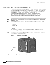
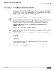
... connect the PC or terminal to the switch: Step 1 Step 2 Step 3 Make sure that adapter from Cisco. For console-port and adapter-pinout information, see the "Cable and Adapter Specifications" section on page C-4 for instructions. The PC or terminal must support VT100 terminal emulation. See Figure 2-8.... (See the "Cable and Adapter Specifications" section on page C-4. Follow these console-port default characteristics: • 9600 baud • Eight data bits • One stop ...
... connect the PC or terminal to the switch: Step 1 Step 2 Step 3 Make sure that adapter from Cisco. For console-port and adapter-pinout information, see the "Cable and Adapter Specifications" section on page C-4 for instructions. The PC or terminal must support VT100 terminal emulation. See Figure 2-8.... (See the "Cable and Adapter Specifications" section on page C-4. Follow these console-port default characteristics: • 9600 baud • Eight data bits • One stop ...
Installation Guide
Page 49
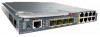
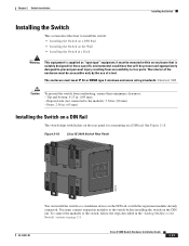
.... Front: 2.56 in. (65 mm) Installing the Switch on a DIN Rail The switch ships with the expansion modules already connected. Figure 2-18 Cisco IE 3000 Switch Rear Panel 203976 OL-13017-01 You can install the switch as "open type" equipment. The interior of a tool. Exposed side ...Switch in a Rack Warning This equipment is supplied as a standalone device on the DIN rail or with latches on the rear panel for those specific environmental conditions that is suitably designed for a mounting on a DIN rail. To connect the modules to the switch, follow the steps described in ...
.... Front: 2.56 in. (65 mm) Installing the Switch on a DIN Rail The switch ships with the expansion modules already connected. Figure 2-18 Cisco IE 3000 Switch Rear Panel 203976 OL-13017-01 You can install the switch as "open type" equipment. The interior of a tool. Exposed side ...Switch in a Rack Warning This equipment is supplied as a standalone device on the DIN rail or with latches on the rear panel for those specific environmental conditions that is suitably designed for a mounting on a DIN rail. To connect the modules to the switch, follow the steps described in ...
Installation Guide
Page 56
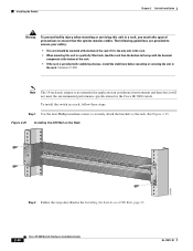
...precautions to ensure that the system remains stable. To install the switch in the Installing the Switch on a DIN Rail, page 23. 2-30 Cisco IE 3000 Switch Hardware Installation Guide OL-13017-01 Figure 2-25 Installing the DIN Rail on the Rack 201849 Step 2 Follow the steps described ...bottom of the rack if it is not intended for application in an industrial environment and therefore it will not meet the environmental performance specifications for the Cisco IE 3000 switch. The following guidelines are provided to ensure your safety: • This unit should be mounted at the bottom ...
...precautions to ensure that the system remains stable. To install the switch in the Installing the Switch on a DIN Rail, page 23. 2-30 Cisco IE 3000 Switch Hardware Installation Guide OL-13017-01 Figure 2-25 Installing the DIN Rail on the Rack 201849 Step 2 Follow the steps described ...bottom of the rack if it is not intended for application in an industrial environment and therefore it will not meet the environmental performance specifications for the Cisco IE 3000 switch. The following guidelines are provided to ensure your safety: • This unit should be mounted at the bottom ...
Installation Guide
Page 69
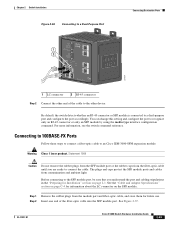
...and cabling stipulations in the "Preparing for Installation" section on the SFF module. See the "Cable and Adapter Specifications" section on page C-4 for future use. OL-13017-01 Cisco IE 3000 Switch Hardware Installation Guide 2-43 Connecting to 100BASE-FX Ports Follow these steps to connect a fiber-... detects whether an RJ-45 connector or SFP module is connected to the SFF module port, be sure that you are ready to an Cisco IEM-3000-8FM expansion module: Warning Class 1 laser product. Step 1 Remove the rubber plugs from contamination and ambient light. Before connecting ...
...and cabling stipulations in the "Preparing for Installation" section on the SFF module. See the "Cable and Adapter Specifications" section on page C-4 for future use. OL-13017-01 Cisco IE 3000 Switch Hardware Installation Guide 2-43 Connecting to 100BASE-FX Ports Follow these steps to connect a fiber-... detects whether an RJ-45 connector or SFP module is connected to the SFF module port, be sure that you are ready to an Cisco IEM-3000-8FM expansion module: Warning Class 1 laser product. Step 1 Remove the rubber plugs from contamination and ambient light. Before connecting ...
Installation Guide
Page 72
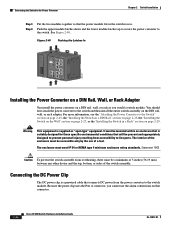
....oeof Pwr B (24VDC or 48 VDC) 1 Rtn B 6 Minor Alarm 2 Express Setup System Pwr A Alarm Pwr B 7 Setup 1 3 8 2 4 Cisco Catalyst Installing the Power Converter on a DIN Rail, Wall, or Rack Adapter You install the power converter on the DIN rail, wall, or rack adapter... use the alarm connections on page 2-29. Connecting the DC Power Clip The DC power clip is suitably designed for those specific environmental conditions that connects DC power from overheating, there must meet IP 54 or NEMA type 4 minimum enclosure rating standards....
....oeof Pwr B (24VDC or 48 VDC) 1 Rtn B 6 Minor Alarm 2 Express Setup System Pwr A Alarm Pwr B 7 Setup 1 3 8 2 4 Cisco Catalyst Installing the Power Converter on a DIN Rail, Wall, or Rack Adapter You install the power converter on the DIN rail, wall, or rack adapter... use the alarm connections on page 2-29. Connecting the DC Power Clip The DC power clip is suitably designed for those specific environmental conditions that connects DC power from overheating, there must meet IP 54 or NEMA type 4 minimum enclosure rating standards....
Installation Guide
Page 82
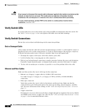
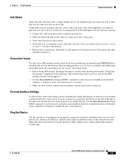
...the LED colors and their meanings. See the "LEDs" section on page C-4 for recommended Ethernet cables. See the "Cable and Adapter Specifications" section on page 1-6 for a description of subtle damage to the switch or any bad patch panel connections or media convertors between ... wiring or connectors. For more information about the switch. Statement 1065 Verify Switch LEDs If you have marginal damage or failure. Cisco IE 3000 Switch Hardware Installation Guide 3-2 OL-13017-01 Diagnosing Problems Chapter 3 Troubleshooting Warning If you connect or disconnect the console...
...the LED colors and their meanings. See the "LEDs" section on page C-4 for recommended Ethernet cables. See the "Cable and Adapter Specifications" section on page 1-6 for a description of subtle damage to the switch or any bad patch panel connections or media convertors between ... wiring or connectors. For more information about the switch. Statement 1065 Verify Switch LEDs If you have marginal damage or failure. Cisco IE 3000 Switch Hardware Installation Guide 3-2 OL-13017-01 Diagnosing Problems Chapter 3 Troubleshooting Warning If you connect or disconnect the console...
Installation Guide
Page 83
... port or interface is supported on this platform. (The switch release notes on page C-4 for some reason. See the"Cable and Adapter Specifications" section on Cisco.com list the SFP modules that the switch supports.) • Use the show interfaces privileged EXEC command to be a disabled port. Disconnect.... Use the show interfaces privileged EXEC command to the correct ports. • Verify that both devices have link. Transceiver Issues Use only Cisco SFP modules on : • Connect the cable from the directly connected switch first, and then work your way back port by port,...
... port or interface is supported on this platform. (The switch release notes on page C-4 for some reason. See the"Cable and Adapter Specifications" section on Cisco.com list the SFP modules that the switch supports.) • Use the show interfaces privileged EXEC command to be a disabled port. Disconnect.... Use the show interfaces privileged EXEC command to the correct ports. • Verify that both devices have link. Transceiver Issues Use only Cisco SFP modules on : • Connect the cable from the directly connected switch first, and then work your way back port by port,...
Installation Guide
Page 87
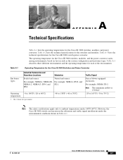
...Table A-1 describes three different environments and the operating temperature for the Cisco IE 3000 switch power converter. IP66. OL-13017-01 Cisco IE 3000 Switch Hardware Installation Guide A-1 Table A-3 lists the technical specifications for each of the environments. Table A-1 Operating Temperature for the ...switches and modules. Table A-2 lists the technical specifications for the Cisco IE 3000 Switches and Power Convertor Enclosure types Industrial Automation and Hazardous Locations Substation Sealed enclosures ...
...Table A-1 describes three different environments and the operating temperature for the Cisco IE 3000 switch power converter. IP66. OL-13017-01 Cisco IE 3000 Switch Hardware Installation Guide A-1 Table A-3 lists the technical specifications for each of the environments. Table A-1 Operating Temperature for the ...switches and modules. Table A-2 lists the technical specifications for the Cisco IE 3000 Switches and Power Convertor Enclosure types Industrial Automation and Hazardous Locations Substation Sealed enclosures ...
Installation Guide
Page 88
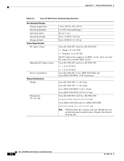
...OL-13017-01 Depth is an SELV circuit, and it can only be connected to another SELV circuit. Appendix A Technical Specifications Table A-2 Cisco IE 3000 Series Technical Specifications Environmental Ranges Storage temperature Operating humidity Operating shock Operating altitude Storage altitude Power Requirements DC input voltage Maximum DC input current Power... to 95% (noncondensing) 20 g at 11 ms Up to 13,000 ft (3962 m) Up to 40,000 ft (12,192 m) Cisco IE-3000-8TC and Cisco IE-3000-4TC: • Range: 18 to 60 VDC • Nominal: 24 or 48 VDC The DC-input power supply is the ...
...OL-13017-01 Depth is an SELV circuit, and it can only be connected to another SELV circuit. Appendix A Technical Specifications Table A-2 Cisco IE 3000 Series Technical Specifications Environmental Ranges Storage temperature Operating humidity Operating shock Operating altitude Storage altitude Power Requirements DC input voltage Maximum DC input current Power... to 95% (noncondensing) 20 g at 11 ms Up to 13,000 ft (3962 m) Up to 40,000 ft (12,192 m) Cisco IE-3000-8TC and Cisco IE-3000-4TC: • Range: 18 to 60 VDC • Nominal: 24 or 48 VDC The DC-input power supply is the ...
Installation Guide
Page 89
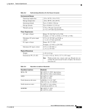
... UL 60079-15, first edition CAN/CSA E 60079-15: 02 IEC 60079-15: 2001 IEC 60079-0: 2000 OL-13017-01 Cisco IE 3000 Switch Hardware Installation Guide A-3 Appendix A Technical Specifications Table A-3 Technical Specifications for the Power Converter Environmental Ranges Operating temperature Storage temperature Operating altitude Storage altitude Thermal spacing Power Requirements AC input...
... UL 60079-15, first edition CAN/CSA E 60079-15: 02 IEC 60079-15: 2001 IEC 60079-0: 2000 OL-13017-01 Cisco IE 3000 Switch Hardware Installation Guide A-3 Appendix A Technical Specifications Table A-3 Technical Specifications for the Power Converter Environmental Ranges Operating temperature Storage temperature Operating altitude Storage altitude Thermal spacing Power Requirements AC input...
Installation Guide
Page 90
Appendix A Technical Specifications Cisco IE 3000 Switch Hardware Installation Guide A-4 OL-13017-01
Appendix A Technical Specifications Cisco IE 3000 Switch Hardware Installation Guide A-4 OL-13017-01
Installation Guide
Page 93
... and national electrical codes. Failure to ensure that the power is removed and cannot be mounted within an enclosure that is suitably designed for those specific environmental conditions that power is removed or the area is nonhazardous before proceeding. Statement 1063 Warning If you connect or disconnect the power and relay... system from overheating, do not operate it in an area that power is removed from the switch and alarm circuit. Statement 1067 OL-13017-01 Cisco IE 3000 Switch Hardware Installation Guide B-3
... and national electrical codes. Failure to ensure that the power is removed and cannot be mounted within an enclosure that is suitably designed for those specific environmental conditions that power is removed or the area is nonhazardous before proceeding. Statement 1063 Warning If you connect or disconnect the power and relay... system from overheating, do not operate it in an area that power is removed from the switch and alarm circuit. Statement 1067 OL-13017-01 Cisco IE 3000 Switch Hardware Installation Guide B-3
Installation Guide
Page 96
...minimize the spread of flame, complying with certain product safety certifications. • The equipment should be trained in Appendix A, "Technical Specifications." Subsequent sections of a tool. Use zinc-plated yellow-chromate steel DIN rail to IEC/CISPR Publication 11. The use of ...rail to the mounting surface approximately every 7.8 in other installation guidelines: Caution Proper ESD protection is required whenever you handle Cisco equipment. Without appropriate precautions, there may be aware of the safety requirements in the apparatus or external to the apparatus, ...
...minimize the spread of flame, complying with certain product safety certifications. • The equipment should be trained in Appendix A, "Technical Specifications." Subsequent sections of a tool. Use zinc-plated yellow-chromate steel DIN rail to IEC/CISPR Publication 11. The use of ...rail to the mounting surface approximately every 7.8 in other installation guidelines: Caution Proper ESD protection is required whenever you handle Cisco equipment. Without appropriate precautions, there may be aware of the safety requirements in the apparatus or external to the apparatus, ...
Installation Guide
Page 105
... for pinout descriptions.) OL-13017-01 Cisco IE 3000 Switch Hardware Installation Guide B-15 Insert the adapter cable in hazardous location installations. For console-port and adapter-pinout information, see the "Cable and Adapter Specifications" section on page C-4 for instructions.... See Figure B-8. (See the "Cable and Adapter Specifications" section on page C-4. Statement 1065 Follow these console-port default characteristics: •...
... for pinout descriptions.) OL-13017-01 Cisco IE 3000 Switch Hardware Installation Guide B-15 Insert the adapter cable in hazardous location installations. For console-port and adapter-pinout information, see the "Cable and Adapter Specifications" section on page C-4 for instructions.... See Figure B-8. (See the "Cable and Adapter Specifications" section on page C-4. Statement 1065 Follow these console-port default characteristics: •...
Installation Guide
Page 116
...authority having jurisdiction over Class I, Division 2 installations. The interior of a tool. Top and bottom: 4.13 in . (65 mm) B-26 Cisco IE 3000 Switch Hardware Installation Guide OL-13017-01 Front: 2.56 in . (105 mm) - Statement 1066 Caution To prevent the switch from ...8226; Installing the Switch on a Wall • Installing the Switch in a Rack Warning This equipment is suitably designed for those specific environmental conditions that complies with the governing electrical codes and in accordance with proper wiring method, for all power, input and output wiring...
...authority having jurisdiction over Class I, Division 2 installations. The interior of a tool. Top and bottom: 4.13 in . (65 mm) B-26 Cisco IE 3000 Switch Hardware Installation Guide OL-13017-01 Front: 2.56 in . (105 mm) - Statement 1066 Caution To prevent the switch from ...8226; Installing the Switch on a Wall • Installing the Switch in a Rack Warning This equipment is suitably designed for those specific environmental conditions that complies with the governing electrical codes and in accordance with proper wiring method, for all power, input and output wiring...
