

Owners Manual
Page 2
..., locate which submaster is overdriving or just want a visual reference of audio production. MX-520O SWUM Your MX-Meterbridge is believing. Whether you also need to "see what you see the music as it 's what your sound system. Individual Meters: Type: Dimensions: Height: Width: Depth: Weight: Power for Meter Lamps Rated at: Meter Range: Meter Resistance: 071-5202-000 004-9830-000...
..., locate which submaster is overdriving or just want a visual reference of audio production. MX-520O SWUM Your MX-Meterbridge is believing. Whether you also need to "see what you see the music as it 's what your sound system. Individual Meters: Type: Dimensions: Height: Width: Depth: Weight: Power for Meter Lamps Rated at: Meter Range: Meter Resistance: 071-5202-000 004-9830-000...
Owners Manual
Page 3
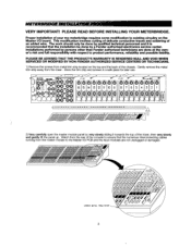
... the panel up. This modification involves cutting of delicate conductive traces and soldering of the chassis. METERBRIDGE INSTALLATION VERY IMPORTANT! PLEASE READ BEFORE INSTALLING YOUR METERBRIDGE. Installations performed by qualified technical personnel and it towards the top of your mx-meterbridge requires some modification to product performance, reliability and possible liability. The work should only be done by a Fender authorized electronics service center.
... the panel up. This modification involves cutting of delicate conductive traces and soldering of the chassis. METERBRIDGE INSTALLATION VERY IMPORTANT! PLEASE READ BEFORE INSTALLING YOUR METERBRIDGE. Installations performed by qualified technical personnel and it towards the top of your mx-meterbridge requires some modification to product performance, reliability and possible liability. The work should only be done by a Fender authorized electronics service center.
Owners Manual
Page 4
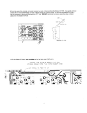
...VIEW OF MASTER I/O PCB (RIBBON CONNECTORS PLUG INTO SOLDER SIDE) CUT TRACE TO P99 PIN 14 P1000-11 I /O PCB. DO NOT disconnect or remove any other wires or ribbon cables from the Master I II ltyll P19 0 13 P69A IYO0C)() 1 fp- %1111■PS 9 lt2 - O - -CR OUTSO - L Rift "CoJ15 AUX2 I /O PCB. In removing...PCB until it is outside the mixer's chassis. 3) From the rear of the console, remove all washer/ nut pairs and screws from the Master I 25 d 1 dia Aor T 110 An\ R4 Inn AUX3 .33 4 CP7 MX-52I6 maw 1g OUTPUTS/t Pr 0, 2 (* INO•t• Ift01.1t0 *5' O(1,...
...VIEW OF MASTER I/O PCB (RIBBON CONNECTORS PLUG INTO SOLDER SIDE) CUT TRACE TO P99 PIN 14 P1000-11 I /O PCB. DO NOT disconnect or remove any other wires or ribbon cables from the Master I II ltyll P19 0 13 P69A IYO0C)() 1 fp- %1111■PS 9 lt2 - O - -CR OUTSO - L Rift "CoJ15 AUX2 I /O PCB. In removing...PCB until it is outside the mixer's chassis. 3) From the rear of the console, remove all washer/ nut pairs and screws from the Master I 25 d 1 dia Aor T 110 An\ R4 Inn AUX3 .33 4 CP7 MX-52I6 maw 1g OUTPUTS/t Pr 0, 2 (* INO•t• Ift01.1t0 *5' O(1,...

Owners Manual
Page 5
... CONNECTORS PLUG INTO SOLDER SIDE) SOLDER WIRE FROM P99 PIN 14 CON SOLDER SIDE) TO P69A PIN 4 CON COMPONENT SIDE) P1000,04 8 O IIPS f2 I r- 6 1 C RO SUTS 1 L RO O 01 11 P ° 0 I Ack I /O PCB and secure it using the washer/nut pairs and screws previously removed in the Meterbridge assembly kit, connect P69 located on the underside of the Master Output Panel...
... CONNECTORS PLUG INTO SOLDER SIDE) SOLDER WIRE FROM P99 PIN 14 CON SOLDER SIDE) TO P69A PIN 4 CON COMPONENT SIDE) P1000,04 8 O IIPS f2 I r- 6 1 C RO SUTS 1 L RO O 01 11 P ° 0 I Ack I /O PCB and secure it using the washer/nut pairs and screws previously removed in the Meterbridge assembly kit, connect P69 located on the underside of the Master Output Panel...
Owners Manual
Page 6
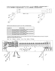
... MX-5216, use hole pairs B and C. A ® Meter side 9) Remove the washer and nut pair for ribbon cables from CHANNEL 9 INSERT and LINE INPUT and CHANNEL 32 INSERT and UNE INPUT jacks. 10) Place the meter bridge assembly on the rear chassis of the meterbridge as indicated below. Remove the washers and nuts from CHANNEL 1 INSERT and LINE INPUT and AUXIUARY OUTPUT 4 and MON OUT 2 jacks. MIXERS MX-5216 W-5224 MX-5232 INSTRUCTIONS Remove...
... MX-5216, use hole pairs B and C. A ® Meter side 9) Remove the washer and nut pair for ribbon cables from CHANNEL 9 INSERT and LINE INPUT and CHANNEL 32 INSERT and UNE INPUT jacks. 10) Place the meter bridge assembly on the rear chassis of the meterbridge as indicated below. Remove the washers and nuts from CHANNEL 1 INSERT and LINE INPUT and AUXIUARY OUTPUT 4 and MON OUT 2 jacks. MIXERS MX-5216 W-5224 MX-5232 INSTRUCTIONS Remove...
Owners Manual
Page 7
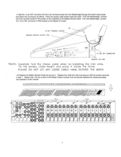
... DIP CONNECTOR MASTER I - Tie the excess cable -length and place it with the screws removed in step 1. PLEASE DO NOT LET ANY LOOSE CABLE HANG OUTSIDE THE MIXER. 12) Replace the Master Module Panel and secure it. From the Meterbridge, connect the ...Output module must be securely fastened for proper grounding and operation of the Master Module Panel. O O1O OO 1.1 40) mer 6 15 14 13 12 11 1 10 9 8 7 6 5 4 3 2 I /O PCB *NOTE: Carefully fold the ribbon cable when re -installing the trim strip. 11) Slip the 14-pin DIP connector and the 8-pin terminal socket from the Meterbridge...
... DIP CONNECTOR MASTER I - Tie the excess cable -length and place it with the screws removed in step 1. PLEASE DO NOT LET ANY LOOSE CABLE HANG OUTSIDE THE MIXER. 12) Replace the Master Module Panel and secure it. From the Meterbridge, connect the ...Output module must be securely fastened for proper grounding and operation of the Master Module Panel. O O1O OO 1.1 40) mer 6 15 14 13 12 11 1 10 9 8 7 6 5 4 3 2 I /O PCB *NOTE: Carefully fold the ribbon cable when re -installing the trim strip. 11) Slip the 14-pin DIP connector and the 8-pin terminal socket from the Meterbridge...
Owners Manual
Page 8
... PAN pot to adjust the meterbridge unless you wish to achieve the desired output level. MAIN L & R 1) Leave the input signal set up and read 0. Assign the input channel to the mains. 2) Place the channel PAN pot at the rear of the console. If necessary, raise or lower the channel fader and/or TRIM control in decibels or RMS volts. Caution: Make sure none...
... PAN pot to adjust the meterbridge unless you wish to achieve the desired output level. MAIN L & R 1) Leave the input signal set up and read 0. Assign the input channel to the mains. 2) Place the channel PAN pot at the rear of the console. If necessary, raise or lower the channel fader and/or TRIM control in decibels or RMS volts. Caution: Make sure none...