User Manual
Page 3
...can radiate radio frequency energy and, if not installed and used in a commercial environment. IN NO EVENT WILL HIKVISION, ITS DIRECTORS, OFFICERS, EMPLOYEES, OR AGENTS BE LIABLE TO YOU FOR ANY SPECIAL, CONSEQUENTIAL, INCIDENTAL, OR ...ORDER TO ENSURE THAT YOUR USE CONFORMS THE APPLICABLE LAW. User Manual of the FCC Rules. HIKVISION SHALL NOT TAKE ANY RESPONSIBILITES FOR ABNORMAL OPERATION, PRIVACY LEAKAGE OR OTHER DAMAGES RESULTING FROM CYBER ... RISKS. These limits are designed to part 15 of Network Camera FITNESS FOR A PARTICULAR PURPOSE, AND NON-INFRINGEMENT OF THIRD PARTY.
...can radiate radio frequency energy and, if not installed and used in a commercial environment. IN NO EVENT WILL HIKVISION, ITS DIRECTORS, OFFICERS, EMPLOYEES, OR AGENTS BE LIABLE TO YOU FOR ANY SPECIAL, CONSEQUENTIAL, INCIDENTAL, OR ...ORDER TO ENSURE THAT YOUR USE CONFORMS THE APPLICABLE LAW. User Manual of the FCC Rules. HIKVISION SHALL NOT TAKE ANY RESPONSIBILITES FOR ABNORMAL OPERATION, PRIVACY LEAKAGE OR OTHER DAMAGES RESULTING FROM CYBER ... RISKS. These limits are designed to part 15 of Network Camera FITNESS FOR A PARTICULAR PURPOSE, AND NON-INFRINGEMENT OF THIRD PARTY.
User Manual
Page 4
... a battery that may cause undesired operation. The battery is marked with this product to the following two conditions: 1. FCC Conditions This device complies with part 15 of the FCC Rules. Industry Canada ICES-003 Compliance 4 the supplied accessories too are marked with "CE" and comply therefore with the applicable harmonized European...
... a battery that may cause undesired operation. The battery is marked with this product to the following two conditions: 1. FCC Conditions This device complies with part 15 of the FCC Rules. Industry Canada ICES-003 Compliance 4 the supplied accessories too are marked with "CE" and comply therefore with the applicable harmonized European...
User Manual
Page 8
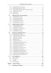
... Detection 98 6.6.11 Configuring Line Crossing Detection 99 6.6.12 Configuring Intrusion Detection 101 6.6.13 Configuring Region Entrance Detection 103 6.6.14 Configuring Region Exiting Detection 104 6.6.15 Configuring Unattended Baggage Detection 105 6.6.16 Configuring Object Removal Detection 107 6.7 VCA Configuration 109 6.7.1 Behavior Analysis ...109 6.7.2 Face Capture ...116 6.7.3 Heat Map ...119 6.7.4 People Counting...
... Detection 98 6.6.11 Configuring Line Crossing Detection 99 6.6.12 Configuring Intrusion Detection 101 6.6.13 Configuring Region Entrance Detection 103 6.6.14 Configuring Region Exiting Detection 104 6.6.15 Configuring Unattended Baggage Detection 105 6.6.16 Configuring Object Removal Detection 107 6.7 VCA Configuration 109 6.7.1 Behavior Analysis ...109 6.7.2 Face Capture ...116 6.7.3 Heat Map ...119 6.7.4 People Counting...
User Manual
Page 15
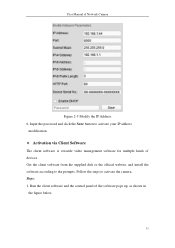
Get the client software from the supplied disk or the official website, and install the software according to activate the camera. Steps: 1. Input the password and click the Save button to activate your IP address modification. Activation via Client Software The client software is versatile video management software for multiple kinds of the software pops up, as shown in the figure below. 15 Run the client software and the control panel of devices. Follow the steps to the prompts. User Manual of Network Camera Figure 2-5 Modify the IP Address 6.
Get the client software from the supplied disk or the official website, and install the software according to activate the camera. Steps: 1. Input the password and click the Save button to activate your IP address modification. Activation via Client Software The client software is versatile video management software for multiple kinds of the software pops up, as shown in the figure below. 15 Run the client software and the control panel of devices. Follow the steps to the prompts. User Manual of Network Camera Figure 2-5 Modify the IP Address 6.
User Manual
Page 53
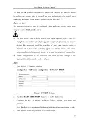
... network devices. Enter the user name and password to enable the feature. 3. Enter the 802.1X Settings interface: Configuration > Advanced Configuration > Network > 802.1X Figure 6-15 802.1X Settings 2. Check the Enable IEEE 802.1X checkbox to access the server. 53 Steps: 1. The password should be something of your product. ...
... network devices. Enter the user name and password to enable the feature. 3. Enter the 802.1X Settings interface: Configuration > Advanced Configuration > Network > 802.1X Figure 6-15 802.1X Settings 2. Check the Enable IEEE 802.1X checkbox to access the server. 53 Steps: 1. The password should be something of your product. ...
User Manual
Page 105
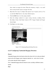
... regions. 8. You can be set the arming schedule. 9. Click Save to FTP, Trigger Channel and Trigger Alarm Output. 10. Figure 6-65 Configuring Region Exiting Detection 6.6.15 Configuring Unattended Baggage Detection Purpose: Unattended baggage detection function detects the objects left over in the pre-defined region such as the baggage, purse, dangerous...
... regions. 8. You can be set the arming schedule. 9. Click Save to FTP, Trigger Channel and Trigger Alarm Output. 10. Figure 6-65 Configuring Region Exiting Detection 6.6.15 Configuring Unattended Baggage Detection Purpose: Unattended baggage detection function detects the objects left over in the pre-defined region such as the baggage, purse, dangerous...
User Manual
Page 129
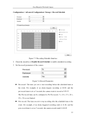
...:05. 129 For example, if an alarm triggered recording ends at 10:00, and the pre-record time is set as No Pre-record, 5 s, 10 s, 15 s, 20 s, 25 s, 30 s or not limited. Post-record: The time you set as 5 seconds, the camera starts to start recording before the scheduled time...
...:05. 129 For example, if an alarm triggered recording ends at 10:00, and the pre-record time is set as No Pre-record, 5 s, 10 s, 15 s, 20 s, 25 s, 30 s or not limited. Post-record: The time you set as 5 seconds, the camera starts to start recording before the scheduled time...
User Manual
Page 157
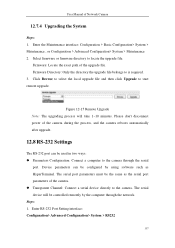
... through the serial port. The serial device will take 1~10 minutes. Enter RS-232 Port Setting interface: Configuration> Advanced Configuration> System > RS232 157 Figure 12-15 Remote Upgrade Note: The upgrading process will be controlled remotely by using software such as the serial port parameters of the camera during the process...
... through the serial port. The serial device will take 1~10 minutes. Enter RS-232 Port Setting interface: Configuration> Advanced Configuration> System > RS232 157 Figure 12-15 Remote Upgrade Note: The upgrading process will be controlled remotely by using software such as the serial port parameters of the camera during the process...
User Manual
Page 160
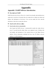
... using this software. Search active devices online Search online devices automatically After launch the SADP software, it automatically searches the online devices every 15 seconds from the subnet where your subnet and displays the information of the devices.
... using this software. Search active devices online Search online devices automatically After launch the SADP software, it automatically searches the online devices every 15 seconds from the subnet where your subnet and displays the information of the devices.
User Manual
Page 161
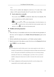
... the network parameter panel. Modify network parameters Steps: 1. User Manual of Network Camera Note: Device can be searched and displayed in the list in 15 seconds after it went offline. Search online devices manually You can also click to refresh the online device list manually. IP address and port...
... the network parameter panel. Modify network parameters Steps: 1. User Manual of Network Camera Note: Device can be searched and displayed in the list in 15 seconds after it went offline. Search online devices manually You can also click to refresh the online device list manually. IP address and port...
Quick Start Guide
Page 4
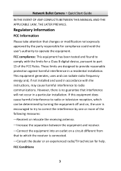
... reception, which can radiate radio frequency energy and, if not installed and used in accordance with the limits for a Class B digital device, pursuant to part 15 of the following measures: -Reorient or relocate the receiving antenna. -Increase the separation between the equipment and receiver. -Connect the equipment into an outlet on...
... reception, which can radiate radio frequency energy and, if not installed and used in accordance with the limits for a Class B digital device, pursuant to part 15 of the following measures: -Reorient or relocate the receiving antenna. -Increase the separation between the equipment and receiver. -Connect the equipment into an outlet on...
Quick Start Guide
Page 5
... marked with this symbol cannot be disposed of it at designated collection points. Network Bullet Camera·Quick Start Guide This device complies with part 15 of as unsorted municipal waste in the European Union.
... marked with this symbol cannot be disposed of it at designated collection points. Network Bullet Camera·Quick Start Guide This device complies with part 15 of as unsorted municipal waste in the European Union.
Quick Start Guide
Page 9
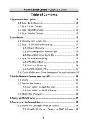
... Contents 1 Appearance Description 10 1.1 Type I Bullet Camera 10 1.2 Type II Bullet Camera 11 1.3 Type III Bullet Camera 12 1.4 Type IV Bullet Camera 13 2 Installation 15 2.1 Memory Card Installation 15 2.2 Type I, II, III Cameras Mounting 17 2.2.1 Direct Mounting 17 2.2.2 Mounting with a Junction Box 20 2.2.3 Mounting with a Gang Box 22 2.3 Type IV Camera Mounting...
... Contents 1 Appearance Description 10 1.1 Type I Bullet Camera 10 1.2 Type II Bullet Camera 11 1.3 Type III Bullet Camera 12 1.4 Type IV Bullet Camera 13 2 Installation 15 2.1 Memory Card Installation 15 2.2 Type I, II, III Cameras Mounting 17 2.2.1 Direct Mounting 17 2.2.2 Mounting with a Junction Box 20 2.2.3 Mounting with a Gang Box 22 2.3 Type IV Camera Mounting...
Quick Start Guide
Page 16
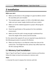
Follow the steps to expose the memory card slot. 15 The IR light from the camera may reflect back into the lens causing reflection. 2.1 Memory Card Installation Type II, Type III and Type IV cameras ...
Follow the steps to expose the memory card slot. 15 The IR light from the camera may reflect back into the lens causing reflection. 2.1 Memory Card Installation Type II, Type III and Type IV cameras ...
Quick Start Guide
Page 27
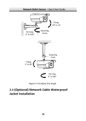
Network Bullet Camera·Quick Start Guide Panning: 0°to 360° Tilting: -30°to 15° Adjusting Screw Tilting: 0°to 90° Adjusting Knob Panning: 0°to 360° Figure 2-14 Adjust the Angle 2.4 (Optional) Network Cable Waterproof Jacket Installation 26
Network Bullet Camera·Quick Start Guide Panning: 0°to 360° Tilting: -30°to 15° Adjusting Screw Tilting: 0°to 90° Adjusting Knob Panning: 0°to 360° Figure 2-14 Adjust the Angle 2.4 (Optional) Network Cable Waterproof Jacket Installation 26
Quick Start Guide
Page 28
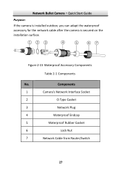
Network Bullet Camera·Quick Start Guide Purpose: If the camera is installed outdoor, you can adapt the waterproof accessory for the network cable after the camera is secured on the installation surface. ①② ③ ④ ⑤ ⑥⑦ Figure 2-15 Waterproof Accessory Components Table 2-1 Components No. Components 1 Camera's Network Interface Socket 2 O-Type Gasket 3 Network Plug 4 Waterproof Endcap 5 Waterproof Rubber Gasket 6 Lock Nut 7 Network Cable from Router/Switch 27
Network Bullet Camera·Quick Start Guide Purpose: If the camera is installed outdoor, you can adapt the waterproof accessory for the network cable after the camera is secured on the installation surface. ①② ③ ④ ⑤ ⑥⑦ Figure 2-15 Waterproof Accessory Components Table 2-1 Components No. Components 1 Camera's Network Interface Socket 2 O-Type Gasket 3 Network Plug 4 Waterproof Endcap 5 Waterproof Rubber Gasket 6 Lock Nut 7 Network Cable from Router/Switch 27
