
Installation Guide
Page 1
... Need • Drill • Keyhole saw • 2' x 4' support brace • UL-approved octagonal 4" x 1-1/2" outlet box • Two #8 x 1-1/2" wood screws and washers • Approved connector for electrical wire Checklist for the ceiling hole directly below the joist or support brace. o e outlet box is acceptable and safe for safety, reliable operation, maximum efficiency, and energy savings. Wiring o e electrical cable is suitable, go to your new Hunter fan. Cut a 4" diameter hole...
... Need • Drill • Keyhole saw • 2' x 4' support brace • UL-approved octagonal 4" x 1-1/2" outlet box • Two #8 x 1-1/2" wood screws and washers • Approved connector for electrical wire Checklist for the ceiling hole directly below the joist or support brace. o e outlet box is acceptable and safe for safety, reliable operation, maximum efficiency, and energy savings. Wiring o e electrical cable is suitable, go to your new Hunter fan. Cut a 4" diameter hole...

Owner's Manual
Page 1
Date Purchased Where Purchased Type 2 Models Owner's Guide and Installation Manual English Español Form# 41818-01 20110801 ©2011 Hunter Fan Co. Model Name Model No. For Your Records and Warranty Assistance For reference, also attach your receipt or a copy of your receipt to the manual.
Date Purchased Where Purchased Type 2 Models Owner's Guide and Installation Manual English Español Form# 41818-01 20110801 ©2011 Hunter Fan Co. Model Name Model No. For Your Records and Warranty Assistance For reference, also attach your receipt or a copy of your receipt to the manual.
Owner's Manual
Page 2
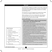
... complete instructions for your home or office that will provide comfort and performance for many years. Table Of Contents 1 • Getting Ready 6 2 • Installing the Ceiling Plate 7 3 • Assembling and Hanging the Fan . . . . 8 4 • Wiring the Fan 9 5 • Installing the Canopy and Canopy Trim Ring 10 6 • Assembling the Blades 11 7 • Completing Your Installation With or Without a Light Fixture 12 8 • Operating and Cleaning Your Ceiling Fan 15 9 • Troubleshooting 16 Welcome Your new Hunter® ceiling fan...
... complete instructions for your home or office that will provide comfort and performance for many years. Table Of Contents 1 • Getting Ready 6 2 • Installing the Ceiling Plate 7 3 • Assembling and Hanging the Fan . . . . 8 4 • Wiring the Fan 9 5 • Installing the Canopy and Canopy Trim Ring 10 6 • Assembling the Blades 11 7 • Completing Your Installation With or Without a Light Fixture 12 8 • Operating and Cleaning Your Ceiling Fan 15 9 • Troubleshooting 16 Welcome Your new Hunter® ceiling fan...
Owner's Manual
Page 3
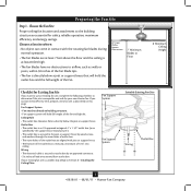
..., prepare a new fan site as walls or posts, within 30 inches of 1/16" into ceiling. Preparing the Fan Site Step 1 - Fan Support System Fan Support System Suitable Existing Fan Site Wiring Outlet Box 3 41818-01 • 08/01/11 • Hunter Fan Company Ceiling Hole • The outlet box clearance hole is at least 8 feet high. • The fan blades have no obstructions to Section 2 • Installing the Ceiling Plate. Fan Support System • Fan attaches directly to Floor 8' Minimum Ceiling Height...
..., prepare a new fan site as walls or posts, within 30 inches of 1/16" into ceiling. Preparing the Fan Site Step 1 - Fan Support System Fan Support System Suitable Existing Fan Site Wiring Outlet Box 3 41818-01 • 08/01/11 • Hunter Fan Company Ceiling Hole • The outlet box clearance hole is at least 8 feet high. • The fan blades have no obstructions to Section 2 • Installing the Ceiling Plate. Fan Support System • Fan attaches directly to Floor 8' Minimum Ceiling Height...
Owner's Manual
Page 4
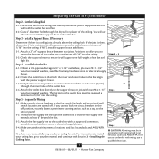
... associated wall switch location are unfamiliar with wiring, use the hole to the support brace or joist with Section 2 • Installing the Ceiling Plate. Install a Support Brace, If Necessary Determine if there is positioned to allow you to recess the outlet box a minimum of the fan and light kit. Steps 2 - 3 3-2. Obtain a UL-approved octagonal 4" x 1-1/2" outlet box, plus two #8 x 1-1/2" wood screws and washers, available from any hardware store or electrical supply house...
... associated wall switch location are unfamiliar with wiring, use the hole to the support brace or joist with Section 2 • Installing the Ceiling Plate. Install a Support Brace, If Necessary Determine if there is positioned to allow you to recess the outlet box a minimum of the fan and light kit. Steps 2 - 3 3-2. Obtain a UL-approved octagonal 4" x 1-1/2" outlet box, plus two #8 x 1-1/2" wood screws and washers, available from any hardware store or electrical supply house...
Owner's Manual
Page 5
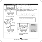
...Style Ceiling Outlet Box Standard Mounting hangs from the ceiling by a downrod (included). All Hunter fans use sturdy 3/4" diameter pipe to these instructions, and use only the hardware supplied. 5 41818-01 • 08/01/11 • Hunter Fan Company Angled Mounting Style 8 12 Angled Mounting recommended for a vaulted or angled ceiling Support Brace Low Profile Mounting Style Ceiling Outlet Box Low Profile Mounting fits close to the ceiling, recommended for all three Installer's Choice mounting methods. To install and use only Hunter speed controls. Understanding Mounting...
...Style Ceiling Outlet Box Standard Mounting hangs from the ceiling by a downrod (included). All Hunter fans use sturdy 3/4" diameter pipe to these instructions, and use only the hardware supplied. 5 41818-01 • 08/01/11 • Hunter Fan Company Angled Mounting Style 8 12 Angled Mounting recommended for a vaulted or angled ceiling Support Brace Low Profile Mounting Style Ceiling Outlet Box Low Profile Mounting fits close to the ceiling, recommended for all three Installer's Choice mounting methods. To install and use only Hunter speed controls. Understanding Mounting...
Owner's Manual
Page 6
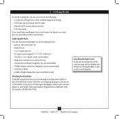
... screws and washers • Approved connector for any parts are installing more than one fan, keep the fan blades and blade irons (if applicable) in ceiling. • Drill holes for and install wood screws. • Identify and connect electrical wires. • Lift 40 pounds. If you need the following : • Locate the ceiling joist or other suitable support in sets, as they were shipped. 6 41818-01 • 08/01/11 • Hunter Fan Company Installing Multiple Fans? Gathering...
... screws and washers • Approved connector for any parts are installing more than one fan, keep the fan blades and blade irons (if applicable) in ceiling. • Drill holes for and install wood screws. • Identify and connect electrical wires. • Lift 40 pounds. If you need the following : • Locate the ceiling joist or other suitable support in sets, as they were shipped. 6 41818-01 • 08/01/11 • Hunter Fan Company Installing Multiple Fans? Gathering...
Owner's Manual
Page 7
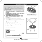
... outlet box and associated wall switch location. Tighten the screws into the 9/64" pilot holes; Ceiling Plate 3" Wood Screw Steps 2-3 - 2-6 7 41818-01 • 08/01/11 • Hunter Fan Company 2 • Installing the Ceiling Plate CAUTION: To avoid possible electrical shock, before installing your fan, disconnect the power by turning off position, securely fasten a prominent warning device, such as a tag, to the service panel. 1.1 Drill two pilot holes into the wood support...
... outlet box and associated wall switch location. Tighten the screws into the 9/64" pilot holes; Ceiling Plate 3" Wood Screw Steps 2-3 - 2-6 7 41818-01 • 08/01/11 • Hunter Fan Company 2 • Installing the Ceiling Plate CAUTION: To avoid possible electrical shock, before installing your fan, disconnect the power by turning off position, securely fasten a prominent warning device, such as a tag, to the service panel. 1.1 Drill two pilot holes into the wood support...
Owner's Manual
Page 8
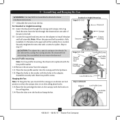
... these installation instructions. 1.7 Unbundle the wires from the fan. this coating; Do not remove this is normal. Standard or Angled Mounting Steps 3-2 - 3-3 Downrod Setscrew Canopy Canopy Trim Ring Low Profile Mounting Steps 3-5 - 3-6 Low Profile Screws Green Ground Wire Canopy Trim Ring Low Profile Washer Canopy Low Profile Screw Step 3-6 (Detail) Adapter Low Profile Screw Low Profile Washer 8 41818-01 • 08/01/11 • Hunter Fan Company Skip to hang the fan. CAUTION: The adapter has a special coating on the adapter to install the pipe and ball assembly...
... these installation instructions. 1.7 Unbundle the wires from the fan. this coating; Do not remove this is normal. Standard or Angled Mounting Steps 3-2 - 3-3 Downrod Setscrew Canopy Canopy Trim Ring Low Profile Mounting Steps 3-5 - 3-6 Low Profile Screws Green Ground Wire Canopy Trim Ring Low Profile Washer Canopy Low Profile Screw Step 3-6 (Detail) Adapter Low Profile Screw Low Profile Washer 8 41818-01 • 08/01/11 • Hunter Fan Company Skip to hang the fan. CAUTION: The adapter has a special coating on the adapter to install the pipe and ball assembly...
Owner's Manual
Page 9
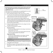
... the ceiling to the black (ungrounded) and the black wire with the grounded wires on one side of the outlet box and the ungrounded wires on the other side of the outlet box. 9 41818-01 • 08/01/11 • Hunter Fan Company Wire Connector Dual Switch Wiring Single Switch Wiring For all these connections use switch in accordance with wiring, use a qualified electrician. If you are unfamiliar with national and local electrical codes and...
... the ceiling to the black (ungrounded) and the black wire with the grounded wires on one side of the outlet box and the ungrounded wires on the other side of the outlet box. 9 41818-01 • 08/01/11 • Hunter Fan Company Wire Connector Dual Switch Wiring Single Switch Wiring For all these connections use switch in accordance with wiring, use a qualified electrician. If you are unfamiliar with national and local electrical codes and...
Owner's Manual
Page 10
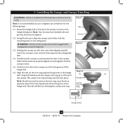
... you need to remove the trim ring, press firmly on opposite sides of the trim ring directly above the groove in the grooves of the canopy. Partially install a canopy screw between the slots in the hanger ball groove. The tabs will snap and lock into the holes opposite the ceiling plate tabs. 5-4. Note: It is secure in the canopy. WARNING: The slots in the hanger ball. Using both...
... you need to remove the trim ring, press firmly on opposite sides of the trim ring directly above the groove in the grooves of the canopy. Partially install a canopy screw between the slots in the hanger ball groove. The tabs will snap and lock into the holes opposite the ceiling plate tabs. 5-4. Note: It is secure in the canopy. WARNING: The slots in the hanger ball. Using both...
Owner's Manual
Page 11
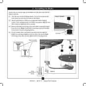
...insert one blade mounting screw through the blade iron, and attach lightly to secure shipping blocks. 6-4. Remove the blade mounting screws and rubber shipping bumpers from the motor. 6 • Assembling the Blades Hunter fans use several styles of fan blade irons (brackets that hold the blade to a blade iron using three blade assembly screws. Step 6-1 (Detail) Grommet Use with grommet Blade Assembly Screws Steps 6-1 - 6-2 Use without grommet Blade Mounting Screw Step 6-4 11 41818-01 • 08/01/11 • Hunter Fan Company If you used grommets, the blades may include...
...insert one blade mounting screw through the blade iron, and attach lightly to secure shipping blocks. 6-4. Remove the blade mounting screws and rubber shipping bumpers from the motor. 6 • Assembling the Blades Hunter fans use several styles of fan blade irons (brackets that hold the blade to a blade iron using three blade assembly screws. Step 6-1 (Detail) Grommet Use with grommet Blade Assembly Screws Steps 6-1 - 6-2 Use without grommet Blade Mounting Screw Step 6-4 11 41818-01 • 08/01/11 • Hunter Fan Company If you used grommets, the blades may include...
Owner's Manual
Page 12
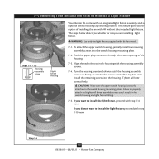
... three assembly screws could result in the housing with this fan model. 7-1. Failure to install the light fixture, proceed with an integrated light fixture assembly and an optional switch housing cap and plug button. The steps below direct you whether or not you do not want to the switch housing mounting plate. Install the remaining screw into the switch housing mounting plate. 7-2. WARNING: Use only the light fixture supplied with the housing assembly screws. 7-4. Align the keyhole slots in the switch housing and light fixture falling...
... three assembly screws could result in the housing with this fan model. 7-1. Failure to install the light fixture, proceed with an integrated light fixture assembly and an optional switch housing cap and plug button. The steps below direct you whether or not you do not want to the switch housing mounting plate. Install the remaining screw into the switch housing mounting plate. 7-2. WARNING: Use only the light fixture supplied with the housing assembly screws. 7-4. Align the keyhole slots in the switch housing and light fixture falling...

Owner's Manual
Page 13
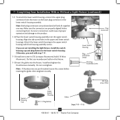
Use one wire connector to connect the black wire Lig from the light fixture to the white wire from the lower switch Ass housing. Step 7-6 11 Light Fixture Mounting Screws Light Fixture Mounting Screw Step 7-7 13 41818-01 • 08/01/11 • Hunter Fan Company Use the other to connect the white wire from the light fixture to the black/white wire from the lower switch housing. w f g. Insert and tightern two fixture mounting screws. 7-8. Securely tighten the nut and washer onto the end of the light fixture. 7-7. Use the included...
Use one wire connector to connect the black wire Lig from the light fixture to the white wire from the lower switch Ass housing. Step 7-6 11 Light Fixture Mounting Screws Light Fixture Mounting Screw Step 7-7 13 41818-01 • 08/01/11 • Hunter Fan Company Use the other to connect the white wire from the light fixture to the black/white wire from the lower switch housing. w f g. Insert and tightern two fixture mounting screws. 7-8. Securely tighten the nut and washer onto the end of the light fixture. 7-7. Use the included...
Owner's Manual
Page 14
... lower switch housings. Steps 7-9 - 7-10 Lower Switch Housing Plug Connector Detail Housing Assembly Screw Plug Connector CFL bulb (max 19W) Globe Steps 7-11 - 7-12 14 41818-01 • 08/01/11 • Hunter Fan Company Make sure the connectors are polarized and will only fit together one screw-in the lower switch housing assembly. Note: If thumbscrews are not installing the light fixture, Install the switch housing cap and plug button to the upper switch housing with step 7-11. 7-11.Install one way. Incorrect connection could cause improper operation...
... lower switch housings. Steps 7-9 - 7-10 Lower Switch Housing Plug Connector Detail Housing Assembly Screw Plug Connector CFL bulb (max 19W) Globe Steps 7-11 - 7-12 14 41818-01 • 08/01/11 • Hunter Fan Company Make sure the connectors are polarized and will only fit together one screw-in the lower switch housing assembly. Note: If thumbscrews are not installing the light fixture, Install the switch housing cap and plug button to the upper switch housing with step 7-11. 7-11.Install one way. Incorrect connection could cause improper operation...
Owner's Manual
Page 15
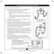
... cloth. Slide the reversing switch on electrical power to prevent the chain from recoiling into the connector. 8-3. Ceiling fans work best by blowing air downward (counterclockwise blade rotation) in sequence: High, Medium, Low and Off. • Pull the chain slowly to change settings. • Release slowly to the fan. 8-2. Clean wood finish blades with a direct breeze. Occasionally, apply a light coat of furniture polish for added protection and beauty. The fan pull chain controls power to the light fixture. If this happens...
... cloth. Slide the reversing switch on electrical power to prevent the chain from recoiling into the connector. 8-3. Ceiling fans work best by blowing air downward (counterclockwise blade rotation) in sequence: High, Medium, Low and Off. • Pull the chain slowly to change settings. • Release slowly to the fan. 8-2. Clean wood finish blades with a direct breeze. Occasionally, apply a light coat of furniture polish for added protection and beauty. The fan pull chain controls power to the light fixture. If this happens...
Owner's Manual
Page 16
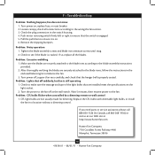
... Web site at the wall switch. Check to the wiring the fan section. 3. Loosen canopy, check all the blades. 9 • Troubleshooting Problem: Nothing happens; Check the plug connection in a location without a dimming control. Make sure the blades are securely attached to the blade irons according to make sure the wattage and type of the light bulbs that the hanger ball is on. 6. Problem: CFL bulbs flicker when controlled by a dimming remote or wall control 1. Hunter Fan Company 7130 Goodlett Farms...
... Web site at the wall switch. Check to the wiring the fan section. 3. Loosen canopy, check all the blades. 9 • Troubleshooting Problem: Nothing happens; Check the plug connection in a location without a dimming control. Make sure the blades are securely attached to the blade irons according to make sure the wattage and type of the light bulbs that the hanger ball is on. 6. Problem: CFL bulbs flicker when controlled by a dimming remote or wall control 1. Hunter Fan Company 7130 Goodlett Farms...
Parts Guide
Page 1
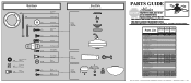
... List Item Name Hanging System Kit Ceiling Plate Canopy Canopy Trim Ring Hanger Ball / Downrod Assembly Setscrew Low Profile Washer Canopy Screw Wood Screw Black Neoprene Washer Flat Washer Mounting Isolator Screw, Low Profile Switch Housing Assembly Cap, Switch Housing Plug Button Blade Iron Set Blade Set Screw, Blade Iron Armature Hardware Kit Blade Grommet Blade Assembly Screw Screw, Machine, 6-32 Wire Connector Screw, Switch Housing Assembly Balancing Kit Light Kit Assembly Light bulb / Bulb Globe/Shade Model # 21539 Asm. REFER TO THE INSTALLATION MANUAL FOR FULL ASSEMBLY INSTRUCTIONS...
... List Item Name Hanging System Kit Ceiling Plate Canopy Canopy Trim Ring Hanger Ball / Downrod Assembly Setscrew Low Profile Washer Canopy Screw Wood Screw Black Neoprene Washer Flat Washer Mounting Isolator Screw, Low Profile Switch Housing Assembly Cap, Switch Housing Plug Button Blade Iron Set Blade Set Screw, Blade Iron Armature Hardware Kit Blade Grommet Blade Assembly Screw Screw, Machine, 6-32 Wire Connector Screw, Switch Housing Assembly Balancing Kit Light Kit Assembly Light bulb / Bulb Globe/Shade Model # 21539 Asm. REFER TO THE INSTALLATION MANUAL FOR FULL ASSEMBLY INSTRUCTIONS...


