Instruction Manual
Page 2
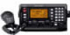
... INSTRUCTION MANUAL. This connection could cause bodily injury. FOREWORD Thank you for purchasing this product should provide you with years of trouble-free operation. This may damage the transceiver. The unit must be hindered or where it could cause a fire or ruin the transceiver. R NEVER place the transceiver where normal oper- and the are registered trademarks of Icom Incorporated (Japan) in direct...
... INSTRUCTION MANUAL. This connection could cause bodily injury. FOREWORD Thank you for purchasing this product should provide you with years of trouble-free operation. This may damage the transceiver. The unit must be hindered or where it could cause a fire or ruin the transceiver. R NEVER place the transceiver where normal oper- and the are registered trademarks of Icom Incorporated (Japan) in direct...

Instruction Manual
Page 3
... Coast Guard by sending a distress call is received), push and hold 1 the PTT switch on the microphone and send the e Follow the guidance displayed on -board 7 TABLE OF CONTENTS 8 FOREWORD i IMPORTANT i EXPLICIT DEFINITIONS i PRECAUTIONS i IN CASE OF EMERGENCY ii TABLE OF CONTENTS ii QUICK REFERENCE I-V I How to set a Channel/Group I I Audio output/squelch adjustment ...... Main unit 4 I Front panel- distress call . 5. line), to...
... Coast Guard by sending a distress call is received), push and hold 1 the PTT switch on the microphone and send the e Follow the guidance displayed on -board 7 TABLE OF CONTENTS 8 FOREWORD i IMPORTANT i EXPLICIT DEFINITIONS i PRECAUTIONS i IN CASE OF EMERGENCY ii TABLE OF CONTENTS ii QUICK REFERENCE I-V I How to set a Channel/Group I I Audio output/squelch adjustment ...... Main unit 4 I Front panel- distress call . 5. line), to...

Instruction Manual
Page 4
... duplex channels. no group separation. D Using the group and channel selectors [GRP] [CH] q Rotate [GRP] to select the desired group. • Available groups are shown in the list below . •During user-programmable channel group use, the channels change in 20 channels steps. *2SITOR use- Example... input digits and retrieves the channel. I How to set the 5 or 6-digit channel number, then push [ENT] • Push [0 DIM] 3 times to 25040 ITU FSK duplex Ch.*2 22 MHz ITU duplex Ch. *1[GRP] changes in 20-channel steps. When selecting Ch. 1. Push [3 SCAN], [5 AGC×] then ...
... duplex channels. no group separation. D Using the group and channel selectors [GRP] [CH] q Rotate [GRP] to select the desired group. • Available groups are shown in the list below . •During user-programmable channel group use, the channels change in 20 channels steps. *2SITOR use- Example... input digits and retrieves the channel. I How to set the 5 or 6-digit channel number, then push [ENT] • Push [0 DIM] 3 times to 25040 ITU FSK duplex Ch.*2 22 MHz ITU duplex Ch. *1[GRP] changes in 20-channel steps. When selecting Ch. 1. Push [3 SCAN], [5 AGC×] then ...

Instruction Manual
Page 5
... set mode. [F] [MODE SET] [2 SQL] [GRP] [CH] SQL L CH ---GPS--- ITEM SEL t Push [MODE SET] to turn the squelch function ON. • Select the desired frequency/channel in the signal. e Rotate [CH] to select the voice squelch function ON and OFF *** SET MODE *** OFF ÇÇ O N ITEM SEL r Turn the power OFF then ON again to adjust the squelch level. • Adjust the level within 1-100 range. When " S P " is displayed...
... set mode. [F] [MODE SET] [2 SQL] [GRP] [CH] SQL L CH ---GPS--- ITEM SEL t Push [MODE SET] to turn the squelch function ON. • Select the desired frequency/channel in the signal. e Rotate [CH] to select the voice squelch function ON and OFF *** SET MODE *** OFF ÇÇ O N ITEM SEL r Turn the power OFF then ON again to adjust the squelch level. • Adjust the level within 1-100 range. When " S P " is displayed...

Instruction Manual
Page 6
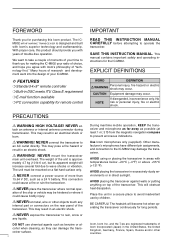
... 0 (low sensitivity) to 9 (maximum sensitivity) range. • Push [MODE SET] to exit the adjustment mode. • Clarity Push [F], [RX CLAR] to switch the clarity function ON and OFF, then rotate [CH] for a while to monitor the transmit frequency of [7 Lo], [8 Mid] or [9 Hi] to select low, middle or high output power, respectively. [7 Lo] [9 Hi] [TUNE THRU] t Push and hold [PTT] on the microphone to turn the...
... 0 (low sensitivity) to 9 (maximum sensitivity) range. • Push [MODE SET] to exit the adjustment mode. • Clarity Push [F], [RX CLAR] to switch the clarity function ON and OFF, then rotate [CH] for a while to monitor the transmit frequency of [7 Lo], [8 Mid] or [9 Hi] to select low, middle or high output power, respectively. [7 Lo] [9 Hi] [TUNE THRU] t Push and hold [PTT] on the microphone to turn the...

Instruction Manual
Page 10
... call . During DSC watch mode and voice/e-mail communication mode when pushed. to turn the power ON. ➥ Push for microphone connector information. Checks and monitors the transmit frequency while holding. (p. 10) ➥ During DSC watch mode, enters RX memory select screen. (p. 38) • [CH] is being received. - The speaker switch is used for 1 sec. o POWER SWITCH [POWER] ➥ Push to make a distress call . (p. 20) ➥...
... call . During DSC watch mode and voice/e-mail communication mode when pushed. to turn the power ON. ➥ Push for microphone connector information. Checks and monitors the transmit frequency while holding. (p. 10) ➥ During DSC watch mode, enters RX memory select screen. (p. 38) • [CH] is being received. - The speaker switch is used for 1 sec. o POWER SWITCH [POWER] ➥ Push to make a distress call . (p. 20) ➥...

Instruction Manual
Page 11
...; Fixes input of channel number and channel comment, etc. ➥When pushed for 1 sec., stores programmed frequency, operating mode and memory comment into a channel. ➥Clears entered digits and retrieves the previous frequency, channel or channel names during DSC watch mode. !7 E-MAIL SWITCH [e-mail] (p. 47) Switches between e-mail operation mode and voice operation mode when pushed. 3 When channel comment indication is ON; switches channel comment indication ON and OFF. 2 PANEL DESCRIPTION !2 FREQUENCY/CHANNEL SWITCH [FREQ/CH...
...; Fixes input of channel number and channel comment, etc. ➥When pushed for 1 sec., stores programmed frequency, operating mode and memory comment into a channel. ➥Clears entered digits and retrieves the previous frequency, channel or channel names during DSC watch mode. !7 E-MAIL SWITCH [e-mail] (p. 47) Switches between e-mail operation mode and voice operation mode when pushed. 3 When channel comment indication is ON; switches channel comment indication ON and OFF. 2 PANEL DESCRIPTION !2 FREQUENCY/CHANNEL SWITCH [FREQ/CH...

Instruction Manual
Page 15
... shows local time.) !1 CHANNEL NUMBER INDICATION Shows the selected channel number. !2 S/RF INDICATOR Shows relative transmit output power levels during transmit and receiving signal strength during receive. !3 NOISE BLANKER INDICATOR (p. 11) "NB" appears when the noise blanker function is activated. !4 SQUELCH INDICATOR (p. 11) "SQL" appears when the squelch is ON. !5 TRANSMIT INDICATOR ➥ "TX" appears during transmit. ➥ "TX" blinks while monitoring a transmit frequency. (p. 10) !6 CHANNEL NAME/RECEIVE FREQUENCY 2 READOUT ➥ Shows the programmed channel names...
... shows local time.) !1 CHANNEL NUMBER INDICATION Shows the selected channel number. !2 S/RF INDICATOR Shows relative transmit output power levels during transmit and receiving signal strength during receive. !3 NOISE BLANKER INDICATOR (p. 11) "NB" appears when the noise blanker function is activated. !4 SQUELCH INDICATOR (p. 11) "SQL" appears when the squelch is ON. !5 TRANSMIT INDICATOR ➥ "TX" appears during transmit. ➥ "TX" blinks while monitoring a transmit frequency. (p. 10) !6 CHANNEL NAME/RECEIVE FREQUENCY 2 READOUT ➥ Shows the programmed channel names...

Instruction Manual
Page 16
... during frequency indication depending on initial set mode setting. (p. 50) D Using the channel selector The transceiver has two large controls for group selection and channel selection. Lat 45 59'N Lon134 44'E L H 16:23 RX L RX L J3E SIMP CH ---GPS--- Lat 45 59'N Lon134 44'E H 16:23 RX L RXå L J3E DUP CH ---GPS--- Channel No. The [GRP] changes channels in 20 channels...
... during frequency indication depending on initial set mode setting. (p. 50) D Using the channel selector The transceiver has two large controls for group selection and channel selection. Lat 45 59'N Lon134 44'E L H 16:23 RX L RX L J3E SIMP CH ---GPS--- Lat 45 59'N Lon134 44'E H 16:23 RX L RXå L J3E DUP CH ---GPS--- Channel No. The [GRP] changes channels in 20 channels...

Instruction Manual
Page 17
...; An ITU SSB channel is open. Channel scan and channel resume scan increase channels within the frequency range between the programmed frequencies on channels 159 and 160. SCAN OPERATION q Rotate [GRP] and [CH], or use the keypad to Ch 160, etc., in initial set mode. J3E L L Sao Itn M1 P43 5 4 59'N 44'E H 16:23 CH ---GPS--Lat 45 59'N 3 D Using scan function The transceiver has automatic channel or frequency change capability (scan function). When...
...; An ITU SSB channel is open. Channel scan and channel resume scan increase channels within the frequency range between the programmed frequencies on channels 159 and 160. SCAN OPERATION q Rotate [GRP] and [CH], or use the keypad to Ch 160, etc., in initial set mode. J3E L L Sao Itn M1 P43 5 4 59'N 44'E H 16:23 CH ---GPS--Lat 45 59'N 3 D Using scan function The transceiver has automatic channel or frequency change capability (scan function). When...

Instruction Manual
Page 18
... -ship channel, the transmit frequency differs from the receive frequency. for a ship-to monitor the transmit frequency. [F] [TX TXF] • "TX" blinks and the display shows the transmit frequency. I Basic voice transmit and receive q Check the following in initial set mode (p. 50). i Release the PTT switch to return to your voice level. • If "SWR" appears, check your antenna system. High power allows longer distance communications and low power reduces power consumption. u Speak...
... -ship channel, the transmit frequency differs from the receive frequency. for a ship-to monitor the transmit frequency. [F] [TX TXF] • "TX" blinks and the display shows the transmit frequency. I Basic voice transmit and receive q Check the following in initial set mode (p. 50). i Release the PTT switch to return to your voice level. • If "SWR" appears, check your antenna system. High power allows longer distance communications and low power reduces power consumption. u Speak...
Instruction Manual
Page 19
... be useful for receive D Squelch function The squelch function detects signals with the RF gain setting. w Rotate [CH] to set the desired minimum cutting level. • "0 (low sensitivity)" to remove undesired weak signals while monitoring strong signals. 4 RECEIVE AND TRANSMIT I Functions for setting a minimum level at which to hear signals. D RF gain setting The receiver gain can be turned OFF. 4 ➥ Push [F] then [1 NB] to switch the...
... be useful for receive D Squelch function The squelch function detects signals with the RF gain setting. w Rotate [CH] to set the desired minimum cutting level. • "0 (low sensitivity)" to remove undesired weak signals while monitoring strong signals. 4 RECEIVE AND TRANSMIT I Functions for setting a minimum level at which to hear signals. D RF gain setting The receiver gain can be turned OFF. 4 ➥ Push [F] then [1 NB] to switch the...

Instruction Manual
Page 20
... the audio readability. • Adjustable between ±150 Hz in 10 Hz steps. D Tuner through function In the combination with direction appear. 4 RECEIVE AND TRANSMIT I CW operation The transceiver has the following CW keying features selectable in set mode as described on your antenna element length. ➥While "TUNE" is displayed, push [F] [TUNE THRU] to tuner through function can compensate by using the...
... the audio readability. • Adjustable between ±150 Hz in 10 Hz steps. D Tuner through function In the combination with direction appear. 4 RECEIVE AND TRANSMIT I CW operation The transceiver has the following CW keying features selectable in set mode as described on your antenna element length. ➥While "TUNE" is displayed, push [F] [TUNE THRU] to tuner through function can compensate by using the...
Instruction Manual
Page 21
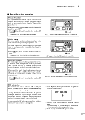
w Select the desired channel to operate FSK mode. • FSK ITU channel group, Ch 4001 to Ch 25040, are in use. NOTE: ➥ FSK tone, shift frequency and FSK polarity can be adjusted in oscillator; use J2B when using the built-in initial set mode (p. 51) ➥ Some transceivers may operate 1.7 kHz higher than the IC-M802's J2B mode even when the same displayed frequencies are only available when...
w Select the desired channel to operate FSK mode. • FSK ITU channel group, Ch 4001 to Ch 25040, are in use. NOTE: ➥ FSK tone, shift frequency and FSK polarity can be adjusted in oscillator; use J2B when using the built-in initial set mode (p. 51) ➥ Some transceivers may operate 1.7 kHz higher than the IC-M802's J2B mode even when the same displayed frequencies are only available when...
Instruction Manual
Page 22
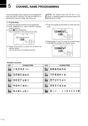
... initial set mode. (p. 50). Lat 45 59'N Lon134 44'E L H 16:23 y Repeat steps r and t to program the channel name. u Push [ENT] to enter the channel name. NOTE: The display type must be helpful for each user and ITU channel. D Programming q Select the desired channel to be assigned for indicating the frequency usage, ship name, etc. RX J3E DUP CH ---GPS--- w Push [FREQ...
... initial set mode. (p. 50). Lat 45 59'N Lon134 44'E L H 16:23 y Repeat steps r and t to program the channel name. u Push [ENT] to enter the channel name. NOTE: The display type must be helpful for each user and ITU channel. D Programming q Select the desired channel to be assigned for indicating the frequency usage, ship name, etc. RX J3E DUP CH ---GPS--- w Push [FREQ...

Instruction Manual
Page 24
... and holding [MODE SET] push [POWER] to enter initial set mode. • Turn the power OFF in advance. [MODE SET] [POWER] w Rotate [GRP] to select the "GPS DISPLAY" then rotate [CH] to select the desired position indication type from a GPS receiver, etc., is applied to [GPS] connector, your position and the UTC time via the keypad, then push [ENT] • Push [3 SCAN] for the...
... and holding [MODE SET] push [POWER] to enter initial set mode. • Turn the power OFF in advance. [MODE SET] [POWER] w Rotate [GRP] to select the "GPS DISPLAY" then rotate [CH] to select the desired position indication type from a GPS receiver, etc., is applied to [GPS] connector, your position and the UTC time via the keypad, then push [ENT] • Push [3 SCAN] for the...

Instruction Manual
Page 26
... is automatically transmitted when the [CANCEL/CALL] is not being received. Position data : According to receive an acknowledgement call is pushed. Distress nature : Undesignated distress. mation. • Distress call NOTE: • Distress alert (simple operation) contains (default); 7 CALL PROCEDURE D Simple distress call repeats every 3.5-4.5 min., until receiving an acknowledgement. • Beep (Pi, Pi) sounds with the maximum audio level every...
... is automatically transmitted when the [CANCEL/CALL] is not being received. Position data : According to receive an acknowledgement call is pushed. Distress nature : Undesignated distress. mation. • Distress call NOTE: • Distress alert (simple operation) contains (default); 7 CALL PROCEDURE D Simple distress call repeats every 3.5-4.5 min., until receiving an acknowledgement. • Beep (Pi, Pi) sounds with the maximum audio level every...

Instruction Manual
Page 33
.... to transmit the urgency call. • The transceiver is set to select the DSC menu. 7 CALL PROCEDURE D Urgency call operation q Push [MODE SET] to the traffic frequency after the call transmission. • Push and hold [CANCEL/CALL] for 1 sec. Safety ÇUrgency SEL OK r Rotate [CH] to select a traffic frequency from one of the pre-programmed frequencies or "Manual set i Announce...
.... to transmit the urgency call. • The transceiver is set to select the DSC menu. 7 CALL PROCEDURE D Urgency call operation q Push [MODE SET] to the traffic frequency after the call transmission. • Push and hold [CANCEL/CALL] for 1 sec. Safety ÇUrgency SEL OK r Rotate [CH] to select a traffic frequency from one of the pre-programmed frequencies or "Manual set i Announce...
Instruction Manual
Page 53
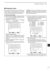
... for scan frequency) have been programmed. DSC MENU OPERATION 10 I Frequency input A total of 50 frequency pairs can be assigned as "Call frequency," "Traffic frequency" or "Scan frequency." character frequency name, and both transmit and receive frequencies, then push [ENT]. • Rotate [CH] to select setup menu. • The select screen is displayed. ******** Set up Call frequency ---- ******** Set up Traffic frequency --- ******** Set up Scan frequency ---- They are also programmed together with the frequency. D SETTING PROCEDURES: q During DSC menu indication...
... for scan frequency) have been programmed. DSC MENU OPERATION 10 I Frequency input A total of 50 frequency pairs can be assigned as "Call frequency," "Traffic frequency" or "Scan frequency." character frequency name, and both transmit and receive frequencies, then push [ENT]. • Rotate [CH] to select setup menu. • The select screen is displayed. ******** Set up Call frequency ---- ******** Set up Traffic frequency --- ******** Set up Scan frequency ---- They are also programmed together with the frequency. D SETTING PROCEDURES: q During DSC menu indication...
Instruction Manual
Page 73
... radio frequencies. Most manufacturers of Loran weather fax and marine single sideband sets don't provide an easy way of adding ground foil to the stern end of low and high frequency radio gear. Non-metal hull or keel boats require yards and yards of piercing through -hull bronze fittings, water tanks, copper hydraulic lines, and anything will work...
... radio frequencies. Most manufacturers of Loran weather fax and marine single sideband sets don't provide an easy way of adding ground foil to the stern end of low and high frequency radio gear. Non-metal hull or keel boats require yards and yards of piercing through -hull bronze fittings, water tanks, copper hydraulic lines, and anything will work...


