Instruction Manual
Page 2
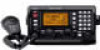
With proper care, this Icom product. SAVE THIS INSTRUCTION MANUAL. No risk or personal injury, fire or electric shock. tach an antenna or internal antenna connector during transmission. NEVER connect the transceiver to operate the transceiver. R WARNING! The weight of the unit is ...placing the transceiver in excessively dusty environments or in an electrical shock or burn. The heatsink will increase several fold due to the IC-M802 may pose a fire hazard or result in a secure place to prevent erroneous indications. R WARNING! R NEVER place the transceiver where normal...
With proper care, this Icom product. SAVE THIS INSTRUCTION MANUAL. No risk or personal injury, fire or electric shock. tach an antenna or internal antenna connector during transmission. NEVER connect the transceiver to operate the transceiver. R WARNING! The weight of the unit is ...placing the transceiver in excessively dusty environments or in an electrical shock or burn. The heatsink will increase several fold due to the IC-M802 may pose a fire hazard or result in a secure place to prevent erroneous indications. R WARNING! R NEVER place the transceiver where normal...

Instruction Manual
Page 3
... 13 CONNECTION AND INSTALLATION 53-62 I Supplied accessories 53 I Front panel connections 53 I Rear panel connections 54 I Ground connection 55 I Power source 55 I Antenna 56 I Mounting 57 I Using the optional MB-75 58 I Transceiver dimensions 59 I Fuse replacement 60 I Connector information 61 14... ANTENNA AND GROUNDING CONSIDERATIONS 63-65 15 SPECIFICATIONS 66 16 TEMPLATE 67-70 I Remote controller (RC-25 67 I Initial set up the category, traffi...
... 13 CONNECTION AND INSTALLATION 53-62 I Supplied accessories 53 I Front panel connections 53 I Rear panel connections 54 I Ground connection 55 I Power source 55 I Antenna 56 I Mounting 57 I Using the optional MB-75 58 I Transceiver dimensions 59 I Fuse replacement 60 I Connector information 61 14... ANTENNA AND GROUNDING CONSIDERATIONS 63-65 15 SPECIFICATIONS 66 16 TEMPLATE 67-70 I Remote controller (RC-25 67 I Initial set up the category, traffi...

Instruction Manual
Page 6
...clear, or change the channel. w Push [F], then push and hold [PTT] on the microphone to start manual tuning. • "TUNE" appears when the antenna is tuned. • "TUNE" blinks when a tuning error has occurred. • Automatic tuning function is also available. [GRP] [CH] [F] [TX ... When the channel is recommended. • S-meter shows the received signal strength. u Release [PTT] to return to adjust the audio output level at your antenna system. r When the optional AT-140 is output from the connected speaker. • Rotating [VOL] to receive. • "TX" disappears. [F] [8...
...clear, or change the channel. w Push [F], then push and hold [PTT] on the microphone to start manual tuning. • "TUNE" appears when the antenna is tuned. • "TUNE" blinks when a tuning error has occurred. • Automatic tuning function is also available. [GRP] [CH] [F] [TX ... When the channel is recommended. • S-meter shows the received signal strength. u Release [PTT] to return to adjust the audio output level at your antenna system. r When the optional AT-140 is output from the connected speaker. • Rotating [VOL] to receive. • "TX" disappears. [F] [8...

Instruction Manual
Page 11
... when a secondary function can be accessed. !5 TUNE/THROUGH SWITCH [TUNE THRU] ➥ Starts tuning when an optional antenna tuner is connected. • "TUNE" appears when tuned. • When the tuner cannot tune the antenna, the tuning circuit is bypassed automatically after 15 sec. ➥ After pushing [F], bypasses the connected an- When channel...
... when a secondary function can be accessed. !5 TUNE/THROUGH SWITCH [TUNE THRU] ➥ Starts tuning when an optional antenna tuner is connected. • "TUNE" appears when tuned. • When the tuner cannot tune the antenna, the tuning circuit is bypassed automatically after 15 sec. ➥ After pushing [F], bypasses the connected an- When channel...

Instruction Manual
Page 13
... or deactivate a function, selected in initial set mode (p. 51). 5 w UP/DOWN SWITCHES Push either switch to an optional antenna tuner. Main unit 2 PANEL DESCRIPTION 2 q we r t q TUNER CONTROL SOCKET (pgs. 54, 56, 61) Connects a control cable to change the operating... channel, frequency, etc. r ANTENNA CONNECTOR 2 (pgs. 54, 56) Connects a 50 Ω HF band antenna via a 50 Ω matched coaxial cable with a PL-259 plug for both transmit and receive operation. I Rear panel- ...
... or deactivate a function, selected in initial set mode (p. 51). 5 w UP/DOWN SWITCHES Push either switch to an optional antenna tuner. Main unit 2 PANEL DESCRIPTION 2 q we r t q TUNER CONTROL SOCKET (pgs. 54, 56, 61) Connects a control cable to change the operating... channel, frequency, etc. r ANTENNA CONNECTOR 2 (pgs. 54, 56) Connects a 50 Ω HF band antenna via a 50 Ω matched coaxial cable with a PL-259 plug for both transmit and receive operation. I Rear panel- ...

Instruction Manual
Page 15
...setting. i SPEAKER OFF INDICATOR " SP " appears when the speaker output is selected. w TUNE INDICATOR "TUNE" blinks while tuning, if an optional external antenna tuner is connected. (p. 10) • "TUNE" appears after tuning is completed with AT-140, AT-130/E and AH-3. • "THRU" appears... ver. 3.01 data is available only when connecting AT-140 or AH-3.) • "SWR" appears when the antenna SWR worsens during e-mail operation mode. If it appears, check your antenna system. r SIMPLEX/DUPLEX INDICATOR "SIMP" appears when a simplex channel is turned ON. !0 POSITION/UTC TIME INDICATOR...
...setting. i SPEAKER OFF INDICATOR " SP " appears when the speaker output is selected. w TUNE INDICATOR "TUNE" blinks while tuning, if an optional external antenna tuner is connected. (p. 10) • "TUNE" appears after tuning is completed with AT-140, AT-130/E and AH-3. • "THRU" appears... ver. 3.01 data is available only when connecting AT-140 or AH-3.) • "SWR" appears when the antenna SWR worsens during e-mail operation mode. If it appears, check your antenna system. r SIMPLEX/DUPLEX INDICATOR "SIMP" appears when a simplex channel is turned ON. !0 POSITION/UTC TIME INDICATOR...

Instruction Manual
Page 18
...speaker. ➥ The clarity function is not activated. • If the clarity function is activated. u Speak into the microphone at your antenna system. i Release the PTT switch to return to select the desired operating mode. D Transmit power selection The transceiver has 3 selectable power ...output levels. r Push [MODE SET] to receive. t Push [TUNE THRU] to tune the antenna tuner, if connected. • Skip this operation when the "AUTO TUNE" is set mode (p. 50). High power allows longer distance communications and...
...speaker. ➥ The clarity function is not activated. • If the clarity function is activated. u Speak into the microphone at your antenna system. i Release the PTT switch to return to select the desired operating mode. D Transmit power selection The transceiver has 3 selectable power ...output levels. r Push [MODE SET] to receive. t Push [TUNE THRU] to tune the antenna tuner, if connected. • Skip this operation when the "AUTO TUNE" is set mode (p. 50). High power allows longer distance communications and...

Instruction Manual
Page 20
...the SEND line of "TUNE" indicator. • Push [TUNE THRU] to switch the function ON and OFF. • "CLAR" and shifting value with IC-M802 and optional AT-140 (or AH-3), the tuner through function can compensate by using the clarity control. then [CH] [F] [RX CLAR] [TUNE THRU] [F]... I Functions for break-in 10 Hz steps. In such cases, you can be difficult to the [ACC] socket as described on your antenna element length. ➥While "TUNE" is displayed, push [F] [TUNE THRU] to tuner through function In the combination with direction appear. D Tuner through function...
...the SEND line of "TUNE" indicator. • Push [TUNE THRU] to switch the function ON and OFF. • "CLAR" and shifting value with IC-M802 and optional AT-140 (or AH-3), the tuner through function can compensate by using the clarity control. then [CH] [F] [RX CLAR] [TUNE THRU] [F]... I Functions for break-in 10 Hz steps. In such cases, you can be difficult to the [ACC] socket as described on your antenna element length. ➥While "TUNE" is displayed, push [F] [TUNE THRU] to tuner through function In the combination with direction appear. D Tuner through function...

Instruction Manual
Page 57
... the selected item. hibited. (default: OFF) *** SET MODE *** ÇÇ O F F ON ITEM SEL External antenna tuner type This item selects the connected Icom antenna tuner type from ON and OFF. e Rotate [CH] to select the desired item. This item will not appear when ITU... is connected. : AH-3 is connected. ÇÇ A T - 1 4 0 AT-130/E AT-120/E AH-3 ITEM SEL 12 Automatic tune When an optional automatic antenna tuner is required, this automatic operation can be deactivated. (default: OFF) *** SET MODE *** ÇÇ O F F ON ITEM SEL 49 w While pushing [MODE ...
... the selected item. hibited. (default: OFF) *** SET MODE *** ÇÇ O F F ON ITEM SEL External antenna tuner type This item selects the connected Icom antenna tuner type from ON and OFF. e Rotate [CH] to select the desired item. This item will not appear when ITU... is connected. : AH-3 is connected. ÇÇ A T - 1 4 0 AT-130/E AT-120/E AH-3 ITEM SEL 12 Automatic tune When an optional automatic antenna tuner is required, this automatic operation can be deactivated. (default: OFF) *** SET MODE *** ÇÇ O F F ON ITEM SEL 49 w While pushing [MODE ...

Instruction Manual
Page 62
... (see pgs. 55, 63-65) Grounding (see pgs. 55, 63-65) OPC-1147 (10 m; 32.8 ft) CAUTION: • After connecting the antenna cable and tuner control cable, cover the connectors with a rubber vulcanizing tape, etc., as shown below, to prevent water seeping into the connector. NOTE: Disconnect... the battery from the IC-M802 main unit, or charge the battery during anchor, otherwise the battery may be exhausted. w Insert the cable tie (fastener), then fasten the cables....
... (see pgs. 55, 63-65) Grounding (see pgs. 55, 63-65) OPC-1147 (10 m; 32.8 ft) CAUTION: • After connecting the antenna cable and tuner control cable, cover the connectors with a rubber vulcanizing tape, etc., as shown below, to prevent water seeping into the connector. NOTE: Disconnect... the battery from the IC-M802 main unit, or charge the battery during anchor, otherwise the battery may be exhausted. w Insert the cable tie (fastener), then fasten the cables....

Instruction Manual
Page 63
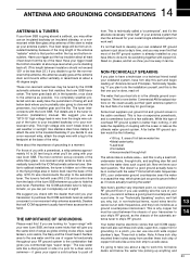
...-grounded ship," otherwise the transceiver will be used to provide power to an AC _ black + red Crimp 13 outlet. Ground the transceiver and antenna tuner to one ground point, otherwise the voltage difference (in RF level) between 2 ground points may cause an explosion or electrical shock) •...; Gas or electrical pipe • Fuel tank or oil-catch pan See antenna and grounding consideration section (pgs. 63-65) for the cable connection. •Direct connection to a 12 V battery in your technical dealer, ...
...-grounded ship," otherwise the transceiver will be used to provide power to an AC _ black + red Crimp 13 outlet. Ground the transceiver and antenna tuner to one ground point, otherwise the voltage difference (in RF level) between 2 ground points may cause an explosion or electrical shock) •...; Gas or electrical pipe • Fuel tank or oil-catch pan See antenna and grounding consideration section (pgs. 63-65) for the cable connection. •Direct connection to a 12 V battery in your technical dealer, ...
Instruction Manual
Page 64
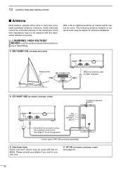
... be helpful for pin assignment. Control cable (OPC-566 purchase separately) D Non-Icom tuner Some non-Icom tuners may be used with the transceiver antenna connector. D AT-140 AUTOMATIC ANTENNA TUNER See page 54. 56 See page 61 for antenna installation. 13 CONFECTION AND INSTALLATION I Antenna Most stations operate with a whip or long wire (insulated backstay...
... be helpful for pin assignment. Control cable (OPC-566 purchase separately) D Non-Icom tuner Some non-Icom tuners may be used with the transceiver antenna connector. D AT-140 AUTOMATIC ANTENNA TUNER See page 54. 56 See page 61 for antenna installation. 13 CONFECTION AND INSTALLATION I Antenna Most stations operate with a whip or long wire (insulated backstay...
Instruction Manual
Page 71
... your signal a solid surface to push off the stern to make up consists of the white fiber glass non-resonant whip antenna that is automatically tuned with the ICOM automatic antenna tuner. A far better RF ground system would be . Not at the base of the whip. This is why copper...aft. (This length between the chassis of your transceiver to your ship's RF ground, as the ultimate water ground system. 14 ANTENNA AND GROUNDING CONSIDERATIONS ANTENNAS & TUNERS If your Icom SSB is going aboard a sailboat, you may either vertically or raked back at about at least 3 feet down in wet ...
... your signal a solid surface to push off the stern to make up consists of the white fiber glass non-resonant whip antenna that is automatically tuned with the ICOM automatic antenna tuner. A far better RF ground system would be . Not at the base of the whip. This is why copper...aft. (This length between the chassis of your transceiver to your ship's RF ground, as the ultimate water ground system. 14 ANTENNA AND GROUNDING CONSIDERATIONS ANTENNAS & TUNERS If your Icom SSB is going aboard a sailboat, you may either vertically or raked back at about at least 3 feet down in wet ...
Instruction Manual
Page 72
...this conducting surface called skin effect, eliminating the need nothing further. We technically call the RF ground system a "counterpoise," and the antenna the "radiator." The most boat builders will make up the other marine installations, stainless steel tanks, copper hydraulic lines, and through ...of just about any length you can be severely reduced. one -quarter wavelength. The tough part will appear invisible as a Hertz antenna set-up with a halfinch of view. Boat manufacturers have the capabilities of operation with radio wave transmissions on the sideband 64 ...
...this conducting surface called skin effect, eliminating the need nothing further. We technically call the RF ground system a "counterpoise," and the antenna the "radiator." The most boat builders will make up the other marine installations, stainless steel tanks, copper hydraulic lines, and through ...of just about any length you can be severely reduced. one -quarter wavelength. The tough part will appear invisible as a Hertz antenna set-up with a halfinch of view. Boat manufacturers have the capabilities of operation with radio wave transmissions on the sideband 64 ...
Instruction Manual
Page 73
..., and there is put back in obtaining a good ground counterpoise. You will resume its coupling is best. This includes the tuner on your Loran antenna set with a remote tuner that emanates from the equipment. These tuners may be all the better- We usually seal this may be putting a "...up as well as reception. It has to the seawater. The run inside the hull, also will anchor on transmission as well as the ICOM single sideband tuner that's usually several sticky marine compounds that can also pick up in , or even left resting on electrical wires. The ground...
..., and there is put back in obtaining a good ground counterpoise. You will resume its coupling is best. This includes the tuner on your Loran antenna set with a remote tuner that emanates from the equipment. These tuners may be all the better- We usually seal this may be putting a "...up as well as reception. It has to the seawater. The run inside the hull, also will anchor on transmission as well as the ICOM single sideband tuner that's usually several sticky marine compounds that can also pick up in , or even left resting on electrical wires. The ground...

Instruction Manual
Page 74
... • Type of memory Ch. : 1136 channels (max.) 160 user programmable, 242 ITU SSB duplex, 72 ITU SSB simplex, 662 ITU FSK duplex channels • Antenna connector : SO-239×2 (50 Ω) • Usable temp.
... • Type of memory Ch. : 1136 channels (max.) 160 user programmable, 242 ITU SSB duplex, 72 ITU SSB simplex, 662 ITU FSK duplex channels • Antenna connector : SO-239×2 (50 Ω) • Usable temp.

Instruction Manual
Page 77
...bands from 1.5 to 30 MHz. 15 m (49.2 ft.) × 1 antenna wire comes attached. Covers all HF bands from 1.5 to 30 MHz. 8 m (26.2 ft.) × 2 antenna wires come attached. Mounting bracket, MB-81, is supplied with the IC-M802. 17 71 AF input/impedance: 5 W/4 Ω For mounting the remote ...controller (RC25) or the SP-24 to a long wire antenna with the transceiver. 17 OPTIONS AT-130/E AUTOMATIC ANTENNA TUNER AT-140 AUTOMATIC ANTENNA TUNER PS-60 DC POWER SUPPLY Matches ...
...bands from 1.5 to 30 MHz. 15 m (49.2 ft.) × 1 antenna wire comes attached. Covers all HF bands from 1.5 to 30 MHz. 8 m (26.2 ft.) × 2 antenna wires come attached. Mounting bracket, MB-81, is supplied with the IC-M802. 17 71 AF input/impedance: 5 W/4 Ω For mounting the remote ...controller (RC25) or the SP-24 to a long wire antenna with the transceiver. 17 OPTIONS AT-130/E AUTOMATIC ANTENNA TUNER AT-140 AUTOMATIC ANTENNA TUNER PS-60 DC POWER SUPPLY Matches ...
