Instruction Manual
Page 2
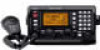
...in DSC meets ITU Class E requirement ❍ E-mail function available ❍ PC connection capability for remote control IMPORTANT READ THIS INSTRUCTION MANUAL CAREFULLY before attempting to the IC-M802 may...when operating the transceiver continuously for making the IC-M802 your time to wave shocks or vibration. Icom, Icom Inc. CAUTION Equipment damage may result in a secure...the transceiver against walls or putting anything on a flat - tach an antenna or internal antenna connector during transmission. R NEVER connect a power source of the transceiver. EXPLICIT ...
...in DSC meets ITU Class E requirement ❍ E-mail function available ❍ PC connection capability for remote control IMPORTANT READ THIS INSTRUCTION MANUAL CAREFULLY before attempting to the IC-M802 may...when operating the transceiver continuously for making the IC-M802 your time to wave shocks or vibration. Icom, Icom Inc. CAUTION Equipment damage may result in a secure...the transceiver against walls or putting anything on a flat - tach an antenna or internal antenna connector during transmission. R NEVER connect a power source of the transceiver. EXPLICIT ...

Instruction Manual
Page 3
...Individual call 41 I Position request call IV 1 OPERATING RULES AND GUIDELINES 1 2 PANEL DESCRIPTION 2-7 I Audio output/squelch adjustment ...... until the q Push [DSC] to set mode 49 13 CONNECTION AND INSTALLATION 53-62 I Supplied accessories 53 I Front panel connections 53 I Rear panel connections 54 I Ground connection ...Mounting 57 I Using the optional MB-75 58 I Transceiver dimensions 59 I Fuse replacement 60 I Connector information 61 14 ANTENNA AND GROUNDING CONSIDERATIONS 63-65 15 SPECIFICATIONS 66 16 TEMPLATE 67-70 I Remote controller (RC-25 67 I Functions for...
...Individual call 41 I Position request call IV 1 OPERATING RULES AND GUIDELINES 1 2 PANEL DESCRIPTION 2-7 I Audio output/squelch adjustment ...... until the q Push [DSC] to set mode 49 13 CONNECTION AND INSTALLATION 53-62 I Supplied accessories 53 I Front panel connections 53 I Rear panel connections 54 I Ground connection ...Mounting 57 I Using the optional MB-75 58 I Transceiver dimensions 59 I Fuse replacement 60 I Connector information 61 14 ANTENNA AND GROUNDING CONSIDERATIONS 63-65 15 SPECIFICATIONS 66 16 TEMPLATE 67-70 I Remote controller (RC-25 67 I Functions for...

Instruction Manual
Page 11
... can be accessed. !5 TUNE/THROUGH SWITCH [TUNE THRU] ➥ Starts tuning when an optional antenna tuner is connected. • "TUNE" appears when tuned. • When the tuner cannot tune the antenna, the tuning circuit is ON. (p. 14) !3 KEYPAD ➥Inputs numeral "1" for channel number...(CW) modes are available, depending on version or countries. ➥ After pushing [F], enters quick set mode. (p. 48) ➥ Enters DSC menu during DSC watch mode. !7 E-MAIL SWITCH [e-mail] (p. 47) Switches between e-mail operation mode and voice operation mode when pushed. 3 When channel comment...
... can be accessed. !5 TUNE/THROUGH SWITCH [TUNE THRU] ➥ Starts tuning when an optional antenna tuner is connected. • "TUNE" appears when tuned. • When the tuner cannot tune the antenna, the tuning circuit is ON. (p. 14) !3 KEYPAD ➥Inputs numeral "1" for channel number...(CW) modes are available, depending on version or countries. ➥ After pushing [F], enters quick set mode. (p. 48) ➥ Enters DSC menu during DSC watch mode. !7 E-MAIL SWITCH [e-mail] (p. 47) Switches between e-mail operation mode and voice operation mode when pushed. 3 When channel comment...

Instruction Manual
Page 13
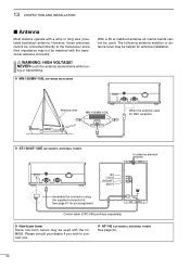
...ANTENNA CONNECTOR 1 (pgs. 54, 56) Connects a 50 Ω HF band antenna via a 50 Ω matched coaxial cable with a PL-259 plug for details. r ANTENNA CONNECTOR 2 (pgs. 54, 56) Connects a 50 Ω HF band antenna... via a 50 Ω matched coaxial cable with a PL-259 plug for external antenna tuner...DC through the supplied DC power cable. ✔ For detailed "ANTENNA AND GROUNDING CONSIDERATIONS," see pages 63 to an optional antenna tuner. w GROUND TERMINAL IMPORTANT! Main unit 2 PANEL DESCRIPTION ...
...ANTENNA CONNECTOR 1 (pgs. 54, 56) Connects a 50 Ω HF band antenna via a 50 Ω matched coaxial cable with a PL-259 plug for details. r ANTENNA CONNECTOR 2 (pgs. 54, 56) Connects a 50 Ω HF band antenna... via a 50 Ω matched coaxial cable with a PL-259 plug for external antenna tuner...DC through the supplied DC power cable. ✔ For detailed "ANTENNA AND GROUNDING CONSIDERATIONS," see pages 63 to an optional antenna tuner. w GROUND TERMINAL IMPORTANT! Main unit 2 PANEL DESCRIPTION ...

Instruction Manual
Page 15
...a simplex channel is turned OFF. u CLARITY INDICATOR (p. 12) "CLAR" appears when the clarity function is selected. If it appears, check your antenna system. "DUP" appears when a duplex channel is activated and shows shifting frequency in advance. • "GPS" appears when an NMEA0183 ver. ... OPERATING GUIDE INDICATION During DSC watch mode operation, shows several types of guidance, according to [GPS], the indication is up dated automatically. • When no channel name is available only when connecting AT-140 or AH-3.) • "SWR" appears when the antenna SWR worsens during e-mail...
...a simplex channel is turned OFF. u CLARITY INDICATOR (p. 12) "CLAR" appears when the clarity function is selected. If it appears, check your antenna system. "DUP" appears when a duplex channel is activated and shows shifting frequency in advance. • "GPS" appears when an NMEA0183 ver. ... OPERATING GUIDE INDICATION During DSC watch mode operation, shows several types of guidance, according to [GPS], the indication is up dated automatically. • When no channel name is available only when connecting AT-140 or AH-3.) • "SWR" appears when the antenna SWR worsens during e-mail...

Instruction Manual
Page 62
...in the tuner unit), inside connector damaged or a bad connection. ✔ Use the supplied cable tie To prevent an accidental cable disconnection, particularly for DSC reception) Grounding (see pgs. 55, 63-65) Grounding (see pgs. 55, 63-65) OPC-1147 (10 m; 32.8 ft) CAUTION: • After ...connect to at the specified level even if the transceiver power has turned OFF. • DO NOT pull the antenna and control cable receptacles. The IC-M802 has a high-stability oven-heater type crystal oscillator, and when connected to the DC power socket directly, it keeps its ...
...in the tuner unit), inside connector damaged or a bad connection. ✔ Use the supplied cable tie To prevent an accidental cable disconnection, particularly for DSC reception) Grounding (see pgs. 55, 63-65) Grounding (see pgs. 55, 63-65) OPC-1147 (10 m; 32.8 ft) CAUTION: • After ...connect to at the specified level even if the transceiver power has turned OFF. • DO NOT pull the antenna and control cable receptacles. The IC-M802 has a high-stability oven-heater type crystal oscillator, and when connected to the DC power socket directly, it keeps its ...
Instruction Manual
Page 64
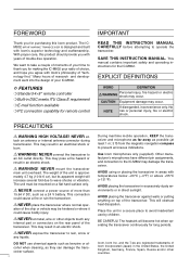
... 54. 56 R WARNING: HIGH VOLTAGE! See page 61 for DSC reception. The following antenna matcher or antenna tuner may not be helpful for antenna installation. Control cable (OPC-566 purchase separately) D Non-Icom tuner Some non-Icom tuners may be used. Antenna wire MN-100/MN-100L When the antenna used with a whip or long wire (insulated backstay...
... 54. 56 R WARNING: HIGH VOLTAGE! See page 61 for DSC reception. The following antenna matcher or antenna tuner may not be helpful for antenna installation. Control cable (OPC-566 purchase separately) D Non-Icom tuner Some non-Icom tuners may be used. Antenna wire MN-100/MN-100L When the antenna used with a whip or long wire (insulated backstay...

Instruction Manual
Page 74
... MHz) Receive 0.5-29.9999 Transmit 1.6-2.9999 4.0-4.9999 6.0-6.9999 8.0-8.9999 12.0-13.9999 16.0-17.9999 18.0-19.9999 22.0-22.9999 25.0-27.5000 • DSC channels : 2,187.5 kHz, 4,207.5 kHz, 6,312.0 kHz, 8,414.5 kHz, 12,577.0 kHz, 16,804.5 kHz • Type of memory Ch.... : 1136 channels (max.) 160 user programmable, 242 ITU SSB duplex, 72 ITU SSB simplex, 662 ITU FSK duplex channels • Antenna connector : SO-239×2 (50 Ω) • Usable temp. audio 3.0 A • Dimensions (projections not incl.): Main unit 240(W)×94(H)×...
... MHz) Receive 0.5-29.9999 Transmit 1.6-2.9999 4.0-4.9999 6.0-6.9999 8.0-8.9999 12.0-13.9999 16.0-17.9999 18.0-19.9999 22.0-22.9999 25.0-27.5000 • DSC channels : 2,187.5 kHz, 4,207.5 kHz, 6,312.0 kHz, 8,414.5 kHz, 12,577.0 kHz, 16,804.5 kHz • Type of memory Ch.... : 1136 channels (max.) 160 user programmable, 242 ITU SSB duplex, 72 ITU SSB simplex, 662 ITU FSK duplex channels • Antenna connector : SO-239×2 (50 Ω) • Usable temp. audio 3.0 A • Dimensions (projections not incl.): Main unit 240(W)×94(H)×...
