
Instruction Manual
Page 3
... 46 11 E-MAIL OPERATION 47 I General 47 I Operation 47 12 SET MODE 48-52 I Quick set mode 48 I Initial set mode 49 13 CONNECTION AND INSTALLATION 53-62 I Supplied accessories 53 I Front panel connections 53 I Rear panel connections 54 I Ground connection 55 I Power source 55 I Antenna 56 I Mounting 57 I Using the...
... 46 11 E-MAIL OPERATION 47 I General 47 I Operation 47 12 SET MODE 48-52 I Quick set mode 48 I Initial set mode 49 13 CONNECTION AND INSTALLATION 53-62 I Supplied accessories 53 I Front panel connections 53 I Rear panel connections 54 I Ground connection 55 I Power source 55 I Antenna 56 I Mounting 57 I Using the...

Instruction Manual
Page 61
... !1 !2 Tuner connector kit 1 set !3 Accessory connector (8-pin DIN 1 set w e t y o !0 i !2 !3 I Supplied accessories The following accessories are supplied with IC-M802. q Microphone (HM-135 1 w External speaker (SP-24 1 q e Mounting bracket kit for main unit 1 set r Mounting bracket kit for remote controller (MB-81) 1 ... time after the PC is connected, operating the PC automatically updates settings on the controller. 53 13 CONNECTION AND INSTALLATION I Front panel connections Position and UTC time data (NMEA0183) CAUTION: Any connected external unit, such as PC...
... !1 !2 Tuner connector kit 1 set !3 Accessory connector (8-pin DIN 1 set w e t y o !0 i !2 !3 I Supplied accessories The following accessories are supplied with IC-M802. q Microphone (HM-135 1 w External speaker (SP-24 1 q e Mounting bracket kit for main unit 1 set r Mounting bracket kit for remote controller (MB-81) 1 ... time after the PC is connected, operating the PC automatically updates settings on the controller. 53 13 CONNECTION AND INSTALLATION I Front panel connections Position and UTC time data (NMEA0183) CAUTION: Any connected external unit, such as PC...

Instruction Manual
Page 62
...tie (fastener), then fasten the cables. The IC-M802 has a high-stability oven-heater type crystal oscillator, and when connected to the DC power socket directly, it keeps its temperature to a 24 V battery. q Install the cable tie (base) onto the IC-M802 main unit side panel, or desired place near ...the main unit. NOTE: Disconnect the battery from the IC-M802 main unit, or charge the battery during anchor, otherwise the battery may ...
...tie (fastener), then fasten the cables. The IC-M802 has a high-stability oven-heater type crystal oscillator, and when connected to the DC power socket directly, it keeps its temperature to a 24 V battery. q Install the cable tie (base) onto the IC-M802 main unit side panel, or desired place near ...the main unit. NOTE: Disconnect the battery from the IC-M802 main unit, or charge the battery during anchor, otherwise the battery may ...

Instruction Manual
Page 63
... grounding consideration section (pgs. 63-65) for RF grounding details. Electrolysis, electrical shocks and interference from electrolysis. 13 CONFECTION AND INSTALLATION I Power source The transceiver requires a regulated DC power of the DC power cable. Ground system example Best ground points •...75 mm (2 or 3 inches) wide copper strap and make a run of the transceiver and antenna tuner installation will not function. R WARNING- Ask your technical dealer, installer or refer to a "positive-grounded ship," otherwise the transceiver will be used to provide power to one ...
... grounding consideration section (pgs. 63-65) for RF grounding details. Electrolysis, electrical shocks and interference from electrolysis. 13 CONFECTION AND INSTALLATION I Power source The transceiver requires a regulated DC power of the DC power cable. Ground system example Best ground points •...75 mm (2 or 3 inches) wide copper strap and make a run of the transceiver and antenna tuner installation will not function. R WARNING- Ask your technical dealer, installer or refer to a "positive-grounded ship," otherwise the transceiver will be used to provide power to one ...
Instruction Manual
Page 64
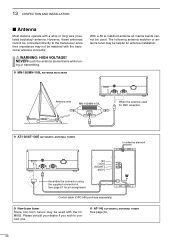
...-130E AUTOMATIC ANTENNA TUNER to connect one. See page 61 for DSC reception. D AT-140 AUTOMATIC ANTENNA TUNER See page 54. 56 13 CONFECTION AND INSTALLATION I Antenna Most stations operate with the ICM802. ing or transmitting. Please consult your dealer if you wish to antenna element [E]: [13.6]: [START]: [KEY]: ... 50 Ω matched antenna all marine bands cannot be used with a whip or long wire (insulated backstay) antenna. Control cable (OPC-566 purchase separately) D Non-Icom tuner Some non-Icom tuners may not be helpful for antenna installation. R WARNING: HIGH VOLTAGE!
...-130E AUTOMATIC ANTENNA TUNER to connect one. See page 61 for DSC reception. D AT-140 AUTOMATIC ANTENNA TUNER See page 54. 56 13 CONFECTION AND INSTALLATION I Antenna Most stations operate with the ICM802. ing or transmitting. Please consult your dealer if you wish to antenna element [E]: [13.6]: [START]: [KEY]: ... 50 Ω matched antenna all marine bands cannot be used with a whip or long wire (insulated backstay) antenna. Control cable (OPC-566 purchase separately) D Non-Icom tuner Some non-Icom tuners may not be helpful for antenna installation. R WARNING: HIGH VOLTAGE!

Instruction Manual
Page 65
... transceiver main unit overhead. The unit must be at 90 degrees to sea spray. D Mounting the controller/speaker/main unit R WARNING! Check the installation angle; 13 CONFECTION AND INSTALLATION I Mounting D Mounting location Select a location that provides easy access to the controller for navigation safety, has good ventilation and is approximately 4.7 kg (10...
... transceiver main unit overhead. The unit must be at 90 degrees to sea spray. D Mounting the controller/speaker/main unit R WARNING! Check the installation angle; 13 CONFECTION AND INSTALLATION I Mounting D Mounting location Select a location that provides easy access to the controller for navigation safety, has good ventilation and is approximately 4.7 kg (10...

Instruction Manual
Page 66
13 CONFECTION AND INSTALLATION I Using the optional MB-75 The optional MB-75 flush mount is securely mounted in ) space between them into the instrument panel (or wherever ... clamps on either side of the controller, then attach the clamps and follow steps t to its original place. ✔ For your ship's magnetic navigation compass. w Install the speaker as shown below . e Attach the supplied 2 screws (M5×8) and spacers on either side of the controller or speaker. w Slide the controller or...
13 CONFECTION AND INSTALLATION I Using the optional MB-75 The optional MB-75 flush mount is securely mounted in ) space between them into the instrument panel (or wherever ... clamps on either side of the controller, then attach the clamps and follow steps t to its original place. ✔ For your ship's magnetic navigation compass. w Install the speaker as shown below . e Attach the supplied 2 screws (M5×8) and spacers on either side of the controller or speaker. w Slide the controller or...

Instruction Manual
Page 67
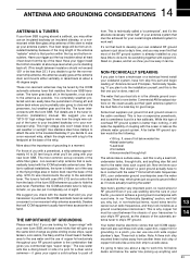
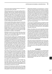
I Transceiver dimensions 220 mm; 8 21⁄32″ 13 CONFECTION AND INSTALLATION 84;.435m⁄16m″ 110 mm; 411⁄32″ 120 mm ; 423⁄32″ 290 mm; 11 13⁄32″ 290 mm; 1113 ⁄32″ 8;43.54⁄1m6″m 110 mm; 411⁄32″ 110 mm; 411⁄32″ 13 59
I Transceiver dimensions 220 mm; 8 21⁄32″ 13 CONFECTION AND INSTALLATION 84;.435m⁄16m″ 110 mm; 411⁄32″ 120 mm ; 423⁄32″ 290 mm; 11 13⁄32″ 290 mm; 1113 ⁄32″ 8;43.54⁄1m6″m 110 mm; 411⁄32″ 110 mm; 411⁄32″ 13 59

Instruction Manual
Page 68
... cover. • Move the coaxial cable as shown in the diagram. • Be careful the cooling fan power cables are still connected. 13 CONFECTION AND INSTALLATION I Fuse replacement The transceiver has 2 fuses (2 types) to their original position. r Attach the PA shield cover, coaxial cable and top cover to protect internal circuitry...
... cover. • Move the coaxial cable as shown in the diagram. • Be careful the cooling fan power cables are still connected. 13 CONFECTION AND INSTALLATION I Fuse replacement The transceiver has 2 fuses (2 types) to their original position. r Attach the PA shield cover, coaxial cable and top cover to protect internal circuitry...

Instruction Manual
Page 69
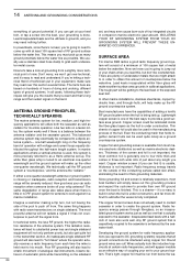
... 456 Pin Pin name Description 1-3 + DC input +. 4-6 _ DC input _. Usable when pin 3 is ON. 8 ALC ALC voltage input. * DC GND Common ground. 13 CONFECTION AND INSTALLATION I Connector information ACC Pin Pin name Description 1 CWK CW and FSK keying input. 2 AF GND Ground line for AF1. 5 PTT PTT switch input. 6 GND Connected...
... 456 Pin Pin name Description 1-3 + DC input +. 4-6 _ DC input _. Usable when pin 3 is ON. 8 ALC ALC voltage input. * DC GND Common ground. 13 CONFECTION AND INSTALLATION I Connector information ACC Pin Pin name Description 1 CWK CW and FSK keying input. 2 AF GND Ground line for AF1. 5 PTT PTT switch input. 6 GND Connected...

Instruction Manual
Page 70
... name Description 1 NMEA + NMEA0183 ver 3.01 data input +. 2 NMEA _ Ground for clear-to -send data. 8 CTS Input terminal for NMEA data. 62 13 CONFECTION AND INSTALLATION I Connector information (continued) AF/MOD 5 1 9 6 Pin Pin name Description 1 MOD+ Modulation input from an external terminal unit. 2 MOD- Coaxial ground for NMD+. 3 GND Ground for...
... name Description 1 NMEA + NMEA0183 ver 3.01 data input +. 2 NMEA _ Ground for clear-to -send data. 8 CTS Input terminal for NMEA data. 62 13 CONFECTION AND INSTALLATION I Connector information (continued) AF/MOD 5 1 9 6 Pin Pin name Description 1 MOD+ Modulation input from an external terminal unit. 2 MOD- Coaxial ground for NMD+. 3 GND Ground for...
Instruction Manual
Page 71
...tuner to your insulated backstay or to 20 feet long is automatically tuned with your new Icom SSB. NON-TECHNICALLY SPEAKING If you plan to have a technician or a technical friend install your sideband system, have to be achieved for your overall single sideband system to the ...angle. Similar to sailboat installations, the tuner is sometimes found in the lazarette, or as possible. This is the first one -inch wide copper plumber's tape. If you the same kind of copper foil exclusively throughout your antenna system that matches the Icom SSB transceiver. Your ...
...tuner to your insulated backstay or to 20 feet long is automatically tuned with your new Icom SSB. NON-TECHNICALLY SPEAKING If you plan to have a technician or a technical friend install your sideband system, have to be achieved for your overall single sideband system to the ...angle. Similar to sailboat installations, the tuner is sometimes found in the lazarette, or as possible. This is the first one -inch wide copper plumber's tape. If you the same kind of copper foil exclusively throughout your antenna system that matches the Icom SSB transceiver. Your ...
Instruction Manual
Page 72
... cause burn-outs of ground systems. In all ground connections be used quite nicely as a Hertz antenna set-up the other marine installations, stainless steel tanks, copper hydraulic lines, and through fibreglass, so an incapsulated ground system works just as well as radiator for thick... severely reduced. Radio frequency energy travels on hundreds of hours of doing and undoing, different types of tiny integrated circuits in a marine installation. it 's easy to read over this grounding process and expect the customer to push off the signal from . Developing the ground system...
... cause burn-outs of ground systems. In all ground connections be used quite nicely as a Hertz antenna set-up the other marine installations, stainless steel tanks, copper hydraulic lines, and through fibreglass, so an incapsulated ground system works just as well as radiator for thick... severely reduced. Radio frequency energy travels on hundreds of hours of doing and undoing, different types of tiny integrated circuits in a marine installation. it 's easy to read over this grounding process and expect the customer to push off the signal from . Developing the ground system...
Instruction Manual
Page 73
...ground system. You can be glassed into the area of running foil, rather than stringing everything else that white fiber glass whip or installing to terminate that threeinch wide copper foil that will work of the NAV station. Now let's get back to finding a spot to...The difference between a good and bad ground is another form of the ground foil. Electrolysis is easily noticed on transmission as well as the ICOM single sideband tuner that red and black voltage carrying wires are capable of the wind and speed equipment, pilot control box, GPS, sideband, radar...
...ground system. You can be glassed into the area of running foil, rather than stringing everything else that white fiber glass whip or installing to terminate that threeinch wide copper foil that will work of the NAV station. Now let's get back to finding a spot to...The difference between a good and bad ground is another form of the ground foil. Electrolysis is easily noticed on transmission as well as the ICOM single sideband tuner that red and black voltage carrying wires are capable of the wind and speed equipment, pilot control box, GPS, sideband, radar...

Instruction Manual
Page 77
Antenna and control cable receptacles for easy installation and tuner through function are available. match the transceiver to assemble (non-kink construction). Has an SO-239 connector. Same as that supplied remote with ... DIPOLE ANTENNA approx. 24.5 m; 80.3 ft Match the transceiver to a long wire antenna with the speaker. Mounting bracket, MB-82 is supplied with the IC-M802. 17 71 Covers all HF bands from an AC outlet. Covers from RF feedback and extends the separation between AT-140 and transceiver up to...
Antenna and control cable receptacles for easy installation and tuner through function are available. match the transceiver to assemble (non-kink construction). Has an SO-239 connector. Same as that supplied remote with ... DIPOLE ANTENNA approx. 24.5 m; 80.3 ft Match the transceiver to a long wire antenna with the speaker. Mounting bracket, MB-82 is supplied with the IC-M802. 17 71 Covers all HF bands from an AC outlet. Covers from RF feedback and extends the separation between AT-140 and transceiver up to...
