Instruction Manual
Page 2
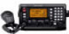
... result in areas with Icom's philosophy of more than 15.64 V DC, such as possible (at least 1 m; 3 ft) from the magnetic navigation compass to thank you for the IC-M802. This may be mounted on top of the transceiver. Other manufacturer's microphones have different pin assignments,... and connection to wave shocks or vibration. Many hours of research and development went into the design of your radio of Icom Incorporated (Japan) in...
... result in areas with Icom's philosophy of more than 15.64 V DC, such as possible (at least 1 m; 3 ft) from the magnetic navigation compass to thank you for the IC-M802. This may be mounted on top of the transceiver. Other manufacturer's microphones have different pin assignments,... and connection to wave shocks or vibration. Many hours of research and development went into the design of your radio of Icom Incorporated (Japan) in...

Instruction Manual
Page 3
... GROUNDING CONSIDERATIONS 63-65 15 SPECIFICATIONS 66 16 TEMPLATE 67-70 I Remote controller (RC-25 67 I Functions for the distress call . Main unit 5 I Microphone (HM-135 5 I LCD screen 6 3 SETTING A CHANNEL 8-9 I Selecting a channel 8 4 RECEIVE AND TRANSMIT .......... 10-13 I Basic voice transmit ...and calling frequency with [CH], [ENT] and keypad. 2 1. " (ship's position) r Push and hold 1 the PTT switch on the microphone and send the e Follow the guidance displayed on -board 7 TABLE OF CONTENTS 8 FOREWORD i IMPORTANT i EXPLICIT DEFINITIONS i PRECAUTIONS i IN CASE ...
... GROUNDING CONSIDERATIONS 63-65 15 SPECIFICATIONS 66 16 TEMPLATE 67-70 I Remote controller (RC-25 67 I Functions for the distress call . Main unit 5 I Microphone (HM-135 5 I LCD screen 6 3 SETTING A CHANNEL 8-9 I Selecting a channel 8 4 RECEIVE AND TRANSMIT .......... 10-13 I Basic voice transmit ...and calling frequency with [CH], [ENT] and keypad. 2 1. " (ship's position) r Push and hold 1 the PTT switch on the microphone and send the e Follow the guidance displayed on -board 7 TABLE OF CONTENTS 8 FOREWORD i IMPORTANT i EXPLICIT DEFINITIONS i PRECAUTIONS i IN CASE ...

Instruction Manual
Page 4
See details on the microphone also selects a channel. When selecting Ch. 1. When selecting Ch. 35. Example; Example; After pushing [0 DIM] 3 times, "-" appears. • Available channel groups and channels Channel No. ...;], [0 DIM], [5 AGC×] then push [ENT]. • When selecting an ITU simplex channel ➥ Push the appropriate numeral keys to set a Channel/Group The IC-M802 has up to set the 3, 4 or 5-digit channel number, then push [ENT] •Pushing [CE] clears input digits and retrieves the channel. When selecting Ch...
See details on the microphone also selects a channel. When selecting Ch. 1. When selecting Ch. 35. Example; Example; After pushing [0 DIM] 3 times, "-" appears. • Available channel groups and channels Channel No. ...;], [0 DIM], [5 AGC×] then push [ENT]. • When selecting an ITU simplex channel ➥ Push the appropriate numeral keys to set a Channel/Group The IC-M802 has up to set the 3, 4 or 5-digit channel number, then push [ENT] •Pushing [CE] clears input digits and retrieves the channel. When selecting Ch...

Instruction Manual
Page 6
...; "TX" appears. • If "SWR" appears during transmit, check your normal voice level. w Push [F], then push and hold [PTT] on the microphone to turn the AGC OFF function ON and OFF. •" AGC" appears when the AGC-OFF function is busy, wait until it becomes clear, or...antenna system. QUICK REFERENCE I Basic voice transmission and reception D Receiving a signal q Select the desired channel via [GRP] and [CH], or keypad. y Speak into the microphone at this moment is also available. [GRP] [CH] [F] [TX TXF] e Push [F] then one of [7 Lo], [8 Mid] or [9 Hi] to select low,...
...; "TX" appears. • If "SWR" appears during transmit, check your normal voice level. w Push [F], then push and hold [PTT] on the microphone to turn the AGC OFF function ON and OFF. •" AGC" appears when the AGC-OFF function is busy, wait until it becomes clear, or...antenna system. QUICK REFERENCE I Basic voice transmission and reception D Receiving a signal q Select the desired channel via [GRP] and [CH], or keypad. y Speak into the microphone at this moment is also available. [GRP] [CH] [F] [TX TXF] e Push [F] then one of [7 Lo], [8 Mid] or [9 Hi] to select low,...

Instruction Manual
Page 10
...] Accepts the supplied or optional microphone. • See p. 66 for appropriate microphones. • See p. 61 for 5 sec. (approx.) to make a distress call. y GROUP SELECTOR [GRP] ➥ Selects groups in sequence ... and voice/e-mail communication mode when pushed. Controller Function display (pgs. 6, 7) !7 !6 !5 !4 q DISTRESS !3 w e r !2 t y q DISTRESS SWITCH [DISTRESS] (p. 18) Push for microphone connector information. u CHANNEL SELECTOR [CH] ➥ Selects an operating channel within the selected channel group such as ITU channels. (p. 8) • User channels can be selected...
...] Accepts the supplied or optional microphone. • See p. 66 for appropriate microphones. • See p. 61 for 5 sec. (approx.) to make a distress call. y GROUP SELECTOR [GRP] ➥ Selects groups in sequence ... and voice/e-mail communication mode when pushed. Controller Function display (pgs. 6, 7) !7 !6 !5 !4 q DISTRESS !3 w e r !2 t y q DISTRESS SWITCH [DISTRESS] (p. 18) Push for microphone connector information. u CHANNEL SELECTOR [CH] ➥ Selects an operating channel within the selected channel group such as ITU channels. (p. 8) • User channels can be selected...

Instruction Manual
Page 13
... 2 PANEL DESCRIPTION 2 q we r t q TUNER CONTROL SOCKET (pgs. 54, 56, 61) Connects a control cable to an optional antenna tuner. Connects a ship's (or vehicle's) ground. I Rear panel- I Microphone (HM-135) q Microphone w e q PTT SWITCH [PTT] Push and hold to transmit; A female connector kit is supplied for DSC receiver.
... 2 PANEL DESCRIPTION 2 q we r t q TUNER CONTROL SOCKET (pgs. 54, 56, 61) Connects a control cable to an optional antenna tuner. Connects a ship's (or vehicle's) ground. I Rear panel- I Microphone (HM-135) q Microphone w e q PTT SWITCH [PTT] Push and hold to transmit; A female connector kit is supplied for DSC receiver.

Instruction Manual
Page 18
... [F] [TX TXF] • "TX" blinks and the display shows the transmit frequency. I Basic voice transmit and receive q Check the following in advance. ➥ Microphone is connected. ➥ No "SQL" indication. • If "SQL" appears, push [F] then [2 SQL] to turn the squelch OFF. ➥ No " SP ...activated. • If the clarity function is activated, push [F] then [RX CLAR] to turn the function OFF. [4 SP×] [2 SQL] Microphone connector [F] [RX CLAR] w Rotate [GRP] and [CH] to select the desired channel to be monitored before transmitting to prevent interference to other ...
... [F] [TX TXF] • "TX" blinks and the display shows the transmit frequency. I Basic voice transmit and receive q Check the following in advance. ➥ Microphone is connected. ➥ No "SQL" indication. • If "SQL" appears, push [F] then [2 SQL] to turn the squelch OFF. ➥ No " SP ...activated. • If the clarity function is activated, push [F] then [RX CLAR] to turn the function OFF. [4 SP×] [2 SQL] Microphone connector [F] [RX CLAR] w Rotate [GRP] and [CH] to select the desired channel to be monitored before transmitting to prevent interference to other ...

Instruction Manual
Page 20
... AND TRANSMIT I CW operation The transceiver has the following CW keying features selectable in (automatic transmission with keying) ➥ OFF (manual transmission with microphone's [PTT], or grounding the SEND line of "TUNE" indicator. • Push [TUNE THRU] to receive. By bypassing the tuner unit, the... break-in A1A mode, push [MODE SET] several times to switch the function ON and OFF. • "CLAR" and shifting value with IC-M802 and optional AT-140 (or AH-3), the tuner through function ON. • "THRU" appears instead of [ACC] connector is possible while transmitting) ...
... AND TRANSMIT I CW operation The transceiver has the following CW keying features selectable in (automatic transmission with keying) ➥ OFF (manual transmission with microphone's [PTT], or grounding the SEND line of "TUNE" indicator. • Push [TUNE THRU] to receive. By bypassing the tuner unit, the... break-in A1A mode, push [MODE SET] several times to switch the function ON and OFF. • "CLAR" and shifting value with IC-M802 and optional AT-140 (or AH-3), the tuner through function ON. • "THRU" appears instead of [ACC] connector is possible while transmitting) ...

Instruction Manual
Page 26
... Lon135 34'E 12:34 Exit r When receiving an acknowledgement, push [CANCEL/CALL] to stop the alarm then reply to the connected station via the transceiver's microphone. • The acknowledgement is not being received. e After transmitting the call, the transceiver is set to the phone emergency frequency automatically (e.g. 2182.0 kHz). • The...
... Lon135 34'E 12:34 Exit r When receiving an acknowledgement, push [CANCEL/CALL] to stop the alarm then reply to the connected station via the transceiver's microphone. • The acknowledgement is not being received. e After transmitting the call, the transceiver is set to the phone emergency frequency automatically (e.g. 2182.0 kHz). • The...

Instruction Manual
Page 27
... AN EMERGENCY. y Rotate [CH] to select the desired distress frequency, then push [ENT]. • After pushing [ENT], return to the connected station via the transceiver's microphone. • The acknowledgement is transmitted on the all distress frequencies (2187.5, 4207.5, 6312.0, 8414.5, 12577.0 and 16804.5 kHz) in sequence when "Single;six frequency" is...
... AN EMERGENCY. y Rotate [CH] to select the desired distress frequency, then push [ENT]. • After pushing [ENT], return to the connected station via the transceiver's microphone. • The acknowledgement is transmitted on the all distress frequencies (2187.5, 4207.5, 6312.0, 8414.5, 12577.0 and 16804.5 kHz) in sequence when "Single;six frequency" is...

Instruction Manual
Page 48
...Geographic" is displayed as below. • Push [CANCEL/CALL] to stop the alarm when an emergency or urgency group call is received. * Group * * ICOM M802 * Exit Traffic Calling station's name appear when the same ID is sent in distress. * Geographic * * 123456789 * Exit Traffic w Push [ENT] to ...any action on your group). < Traffic > RX J3E GPS Lat 34 34'N SP Lon134 34'E 12:34 Exit e Communicate via the microphone with the ship when the calling ship requires such. w Push [ENT] to listen to the traffic frequency for an announcement from ...
...Geographic" is displayed as below. • Push [CANCEL/CALL] to stop the alarm when an emergency or urgency group call is received. * Group * * ICOM M802 * Exit Traffic Calling station's name appear when the same ID is sent in distress. * Geographic * * 123456789 * Exit Traffic w Push [ENT] to ...any action on your group). < Traffic > RX J3E GPS Lat 34 34'N SP Lon134 34'E 12:34 Exit e Communicate via the microphone with the ship when the calling ship requires such. w Push [ENT] to listen to the traffic frequency for an announcement from ...
Instruction Manual
Page 55
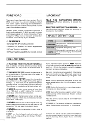
...dealer. RX L [e-mail] mail SIMP WIDE CH ---GPS--- I General The IC-M802 is ready for connection details. NOTE: E-mail mode cannot be programmed by pushing [DSC] in advance. • Pushing [Y]/[Z] on the microphone also selects the channel. • [GRP] rotation changes in advance. Lat 34 34...'N Lon134 34'E H 16:23 10 11 47 11 E-MAIL OPERATION I Operation q Connect your PC via an e-mail modem to [AF/MOD] on the IC-M802 main unit front panel. &#...
...dealer. RX L [e-mail] mail SIMP WIDE CH ---GPS--- I General The IC-M802 is ready for connection details. NOTE: E-mail mode cannot be programmed by pushing [DSC] in advance. • Pushing [Y]/[Z] on the microphone also selects the channel. • [GRP] rotation changes in advance. Lat 34 34...'N Lon134 34'E H 16:23 10 11 47 11 E-MAIL OPERATION I Operation q Connect your PC via an e-mail modem to [AF/MOD] on the IC-M802 main unit front panel. &#...
Instruction Manual
Page 59
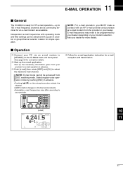
...break-in function (in A1A mode) toggles transmit and receive with some delay time. (default: FULL) Microphone keys This item activates/deactivates the keys on the HM- 135 HAND MICROPHONE to receive signals between transmitted key- When the function is set mode items (continued) FSK shift frequency ... below on how to program the [P] key. (default: ON) [P] key function This item assigns a function to the [P] key on the HM135 HAND MICROPHONE ([P], [∫] and [√]). Full break-in al- This item selects an FSK shift frequency for almost any FSK system from 850 Hz, 425 Hz...
...break-in function (in A1A mode) toggles transmit and receive with some delay time. (default: FULL) Microphone keys This item activates/deactivates the keys on the HM- 135 HAND MICROPHONE to receive signals between transmitted key- When the function is set mode items (continued) FSK shift frequency ... below on how to program the [P] key. (default: ON) [P] key function This item assigns a function to the [P] key on the HM135 HAND MICROPHONE ([P], [∫] and [√]). Full break-in al- This item selects an FSK shift frequency for almost any FSK system from 850 Hz, 425 Hz...

Instruction Manual
Page 61
... is operated. q Microphone (HM-135 1 w External speaker (SP-24 1 q e Mounting bracket kit for main unit 1 set r Mounting bracket kit for remote controller (MB-81) 1 set w e t y o !0 i !2 !3 I Supplied accessories The following accessories are supplied with IC-M802. 13 CONNECTION AND ...10149; When a PC is connected, the controller not being operated is inhibited for speaker (MB-82) ... 1 set y DC power cable (OPC-1107A 1 u Microphone hanger kit 1 set i Cable tie set 1 set o Spare fuses (FGB 30 A 1 u !0 Spare fuses (FGB 5 A 2 !1 Remote control cable...
... is operated. q Microphone (HM-135 1 w External speaker (SP-24 1 q e Mounting bracket kit for main unit 1 set r Mounting bracket kit for remote controller (MB-81) 1 set w e t y o !0 i !2 !3 I Supplied accessories The following accessories are supplied with IC-M802. 13 CONNECTION AND ...10149; When a PC is connected, the controller not being operated is inhibited for speaker (MB-82) ... 1 set y DC power cable (OPC-1107A 1 u Microphone hanger kit 1 set i Cable tie set 1 set o Spare fuses (FGB 30 A 1 u !0 Spare fuses (FGB 5 A 2 !1 Remote control cable...

Instruction Manual
Page 65
... away from your line of the unit is not subject to sea spray. NEVER mount the transceiver main unit overhead. CAUTION: KEEP the transceiver and microphone at some angles. 13 CONFECTION AND INSTALLATION I Mounting D Mounting location Select a location that provides easy access to the controller for navigation safety, has good ventilation...
... away from your line of the unit is not subject to sea spray. NEVER mount the transceiver main unit overhead. CAUTION: KEEP the transceiver and microphone at some angles. 13 CONFECTION AND INSTALLATION I Mounting D Mounting location Select a location that provides easy access to the controller for navigation safety, has good ventilation...

Instruction Manual
Page 66
... above . e Attach the screw and spacer on either side of the controller. r Slide the controller through the hole as below . CAUTION: KEEP the transceiver and microphone at right for mounting the controller and speaker to the body. r Attach the clamps on the other side of the controller, then attach the clamps...
... above . e Attach the screw and spacer on either side of the controller. r Slide the controller through the hole as below . CAUTION: KEEP the transceiver and microphone at right for mounting the controller and speaker to the body. r Attach the clamps on the other side of the controller, then attach the clamps...

Instruction Manual
Page 69
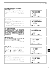
... Pin Pin name Description 1-3 + DC input +. 4-6 _ DC input _. Coaxial ground for AF1. 5 PTT PTT switch input. 6 GND Connected to 0 V Input impedance : More than 10 kΩ MICROPHONE Pin Pin name Description 1 MIC+ Audio input from the mic element. 2 NC No connection qu wiy ert 3 AF1 AF output controlled with [VOL]. 4 AF2 Ground...
... Pin Pin name Description 1-3 + DC input +. 4-6 _ DC input _. Coaxial ground for AF1. 5 PTT PTT switch input. 6 GND Connected to 0 V Input impedance : More than 10 kΩ MICROPHONE Pin Pin name Description 1 MIC+ Audio input from the mic element. 2 NC No connection qu wiy ert 3 AF1 AF output controlled with [VOL]. 4 AF2 Ground...

Instruction Manual
Page 77
... ANTENNA MATCHER MN-100L ANTENNA MATCHER AH-710 FOLDED DIPOLE ANTENNA approx. 24.5 m; 80.3 ft Match the transceiver to 10 m (32.8 ft.). HM-135 HAND MICROPHONE OPC-1147 SHIELDED CONTROL CABLE Shielded control cable protects the transceiver from RF feedback and extends the separation between AT-140 and transceiver up to... AT-130/E AUTOMATIC ANTENNA TUNER AT-140 AUTOMATIC ANTENNA TUNER PS-60 DC POWER SUPPLY Matches the transceiver to a long wire antenna with the IC-M802. 17 71 Has an SO-239 connector. Same as that supplied with the transceiver.
... ANTENNA MATCHER MN-100L ANTENNA MATCHER AH-710 FOLDED DIPOLE ANTENNA approx. 24.5 m; 80.3 ft Match the transceiver to 10 m (32.8 ft.). HM-135 HAND MICROPHONE OPC-1147 SHIELDED CONTROL CABLE Shielded control cable protects the transceiver from RF feedback and extends the separation between AT-140 and transceiver up to... AT-130/E AUTOMATIC ANTENNA TUNER AT-140 AUTOMATIC ANTENNA TUNER PS-60 DC POWER SUPPLY Matches the transceiver to a long wire antenna with the IC-M802. 17 71 Has an SO-239 connector. Same as that supplied with the transceiver.