

Product Specification
Page 5
... 1.1 Power Connector Terminology Change 9 1.2 Overview ...10 1.2.1 Feature Summary 10 1.2.2 Manufacturing Options 11 1.2.3 Board Layout 12 1.2.4 Block Diagram 14 1.3 Online Support ...15 1.4 Processor ...15 1.5 System Memory ...16 1.5.1 Memory Configurations 17 1.6 Intel® 945P Chipset...21 1.6.1 USB ...21 1.6.2 IDE Support 22 1.6.3 Real-Time Clock, CMOS SRAM, and Battery 23 1.7 PCI Express* Connectors 23 1.8 IEEE-1394a Connectors (Optional 24 1.9 Legacy I/O Controller 24 1.9.1 Serial Port...24 1.9.2 Parallel Port 24 1.9.3 Diskette Drive Controller 25 1.9.4 Keyboard and...
... 1.1 Power Connector Terminology Change 9 1.2 Overview ...10 1.2.1 Feature Summary 10 1.2.2 Manufacturing Options 11 1.2.3 Board Layout 12 1.2.4 Block Diagram 14 1.3 Online Support ...15 1.4 Processor ...15 1.5 System Memory ...16 1.5.1 Memory Configurations 17 1.6 Intel® 945P Chipset...21 1.6.1 USB ...21 1.6.2 IDE Support 22 1.6.3 Real-Time Clock, CMOS SRAM, and Battery 23 1.7 PCI Express* Connectors 23 1.8 IEEE-1394a Connectors (Optional 24 1.9 Legacy I/O Controller 24 1.9.1 Serial Port...24 1.9.2 Parallel Port 24 1.9.3 Diskette Drive Controller 25 1.9.4 Keyboard and...

Product Specification
Page 6
...Statement 66 2.15.4 Recycling Considerations 67 2.15.5 Product Certification Markings (Board Level 68 3 Overview of BIOS Features 3.1 Introduction ...69 3.2 BIOS Flash Memory Organization 70 3.3 Resource Configuration 70 3.3.1 PCI Autoconfiguration 70 3.3.2 PCI IDE Support 70 3.4 System Management BIOS (SMBIOS 71 3.5 Legacy USB Support...71 3.6 BIOS Updates ...72 3.6.1 Language Support 72 3.6.2 Custom Splash Screen 72 3.7 Boot Options ...73 3.7.1 CD-ROM Boot 73 3.7.2 Network Boot 73 3.7.3 Booting Without Attached Devices 73 3.7.4 Changing the Default Boot Device During POST 73 vi
...Statement 66 2.15.4 Recycling Considerations 67 2.15.5 Product Certification Markings (Board Level 68 3 Overview of BIOS Features 3.1 Introduction ...69 3.2 BIOS Flash Memory Organization 70 3.3 Resource Configuration 70 3.3.1 PCI Autoconfiguration 70 3.3.2 PCI IDE Support 70 3.4 System Management BIOS (SMBIOS 71 3.5 Legacy USB Support...71 3.6 BIOS Updates ...72 3.6.1 Language Support 72 3.6.2 Custom Splash Screen 72 3.7 Boot Options ...73 3.7.1 CD-ROM Boot 73 3.7.2 Network Boot 73 3.7.3 Booting Without Attached Devices 73 3.7.4 Changing the Default Boot Device During POST 73 vi

Product Specification
Page 7
... and Beep Codes 4.1 Speaker ...77 4.2 BIOS Beep Codes...77 4.3 BIOS Error Messages 77 4.4 Port 80h POST Codes 78 Figures 1. Board Components ...12 2. Block Diagram...14 3. Single Channel (Asymmetric) Mode Configuration with Two DIMMs 18 5. LAN Connector LED Locations 29 13. Connection Diagram for Omni-directional Airflow 61 25. Location of the Standby Power Indicator LED 37 15. Processor Heatsink for Front Panel Connector 53 19. Board Components Shown in Figure 1 13 4. LAN Connector LED States 28 6. Power States and Targeted System Power 33 9. Wake-up Devices and...
... and Beep Codes 4.1 Speaker ...77 4.2 BIOS Beep Codes...77 4.3 BIOS Error Messages 77 4.4 Port 80h POST Codes 78 Figures 1. Board Components ...12 2. Block Diagram...14 3. Single Channel (Asymmetric) Mode Configuration with Two DIMMs 18 5. LAN Connector LED Locations 29 13. Connection Diagram for Omni-directional Airflow 61 25. Location of the Standby Power Indicator LED 37 15. Processor Heatsink for Front Panel Connector 53 19. Board Components Shown in Figure 1 13 4. LAN Connector LED States 28 6. Power States and Targeted System Power 33 9. Wake-up Devices and...
Product Specification
Page 8
... 49 18. Typical Port 80h POST Sequence 82 viii BIOS Error Messages 77 43. Thermal Considerations for Components 63 33. Main Power Connector 51 24. Processor Core Power Connector 51 25. PCI Interrupt Routing Map 46 16. Chassis Intrusion Connector 50 20. Product Certification Markings 68 37. BIOS Setup Program Function Keys 70 39. Auxiliary Front Panel Power/Sleep LED Connector 52 26. Intel Desktop Board D945PAW Technical Product Specification 10. Serial ATA Connectors 50 21. Port 80h POST Codes 79 45.
... 49 18. Typical Port 80h POST Sequence 82 viii BIOS Error Messages 77 43. Thermal Considerations for Components 63 33. Main Power Connector 51 24. Processor Core Power Connector 51 25. PCI Interrupt Routing Map 46 16. Chassis Intrusion Connector 50 20. Product Certification Markings 68 37. BIOS Setup Program Function Keys 70 39. Auxiliary Front Panel Power/Sleep LED Connector 52 26. Intel Desktop Board D945PAW Technical Product Specification 10. Serial ATA Connectors 50 21. Port 80h POST Codes 79 45.

Product Specification
Page 10
...; 945P Chipset, consisting of: • Intel® 82945P Memory Controller Hub (MCH) • Intel® 82801G I/O Controller Hub (ICH7) One PCI Express* x16 bus add-in card connector • Support for PCI Local Bus Specification Revision 2.3 • Support for a description of the board. Intel Desktop Board D945PAW Technical Product Specification 1.2 Overview 1.2.1 Feature Summary Table 1 summarizes the major features of LAN subsystem options. • Intel® BIOS (resident in the SPI Flash device) • Support for Advanced Configuration and Power Interface (ACPI), Plug and...
...; 945P Chipset, consisting of: • Intel® 82945P Memory Controller Hub (MCH) • Intel® 82801G I/O Controller Hub (ICH7) One PCI Express* x16 bus add-in card connector • Support for PCI Local Bus Specification Revision 2.3 • Support for a description of the board. Intel Desktop Board D945PAW Technical Product Specification 1.2 Overview 1.2.1 Feature Summary Table 1 summarizes the major features of LAN subsystem options. • Intel® BIOS (resident in the SPI Flash device) • Support for Advanced Configuration and Power Interface (ACPI), Plug and...

Product Specification
Page 14
...USB Back Panel/Front Panel USB Ports Legacy I/O Controller LPC Bus Serial Port Parallel Port PS/2 Mouse PS/2 Keyboard Diskette Drive Connector Intel 82801G I/O Controller Hub (ICH7) Serial Peripheral Interface (SPI) Flash Device DMI Interconnect High Definition Audio Link LAN Connect Interface Channel A DIMMs (2) Dual-Channel Memory Bus SMBus Channel B DIMMs (2) IEEE-1394a Connectors (Optional) IEEE-1394a Controller (Optional) PCI Bus PCI Bus PCI Slot 1 PCI Slot 2 SMBus Hardware Monitoring and Fan Control ASIC LPC TPM Component Bus (Optional) 10/100 LAN PLC (Optional) LAN...
...USB Back Panel/Front Panel USB Ports Legacy I/O Controller LPC Bus Serial Port Parallel Port PS/2 Mouse PS/2 Keyboard Diskette Drive Connector Intel 82801G I/O Controller Hub (ICH7) Serial Peripheral Interface (SPI) Flash Device DMI Interconnect High Definition Audio Link LAN Connect Interface Channel A DIMMs (2) Dual-Channel Memory Bus SMBus Channel B DIMMs (2) IEEE-1394a Connectors (Optional) IEEE-1394a Controller (Optional) PCI Bus PCI Bus PCI Slot 1 PCI Slot 2 SMBus Hardware Monitoring and Fan Control ASIC LPC TPM Component Bus (Optional) 10/100 LAN PLC (Optional) LAN...

Product Specification
Page 16
... 4 lists the supported DIMM configurations. Intel Desktop Board D945PAW Technical Product Specification 1.5 System Memory The board has four DIMM sockets and support the following memory features: • 1.8 V (only) DDR2 SDRAM DIMMs with gold-plated contacts • Unbuffered, single-sided or double-sided DIMMs with the following restriction: Double-sided DIMMS with DIMMs that support the Serial Presence Detect (SPD) data structure. Refer to correctly configure the memory settings...
... 4 lists the supported DIMM configurations. Intel Desktop Board D945PAW Technical Product Specification 1.5 System Memory The board has four DIMM sockets and support the following memory features: • 1.8 V (only) DDR2 SDRAM DIMMs with gold-plated contacts • Unbuffered, single-sided or double-sided DIMMs with the following restriction: Double-sided DIMMS with DIMMs that support the Serial Presence Detect (SPD) data structure. Refer to correctly configure the memory settings...

Product Specification
Page 22
.... Intel Desktop Board D945PAW Technical Product Specification 1.6.2 IDE Support The board provides five IDE interface connectors: • One parallel ATA IDE connector that supports two devices • Four serial ATA IDE connectors that support one device per port. Native mode is used . The Parallel ATA IDE interface supports the following modes: • Programmed I /O and IRQ resources are faster timings and require a specialized cable to the BIOS. For information about The location of up to Ultra DMA and is device driver compatible...
.... Intel Desktop Board D945PAW Technical Product Specification 1.6.2 IDE Support The board provides five IDE interface connectors: • One parallel ATA IDE connector that supports two devices • Four serial ATA IDE connectors that support one device per port. Native mode is used . The Parallel ATA IDE interface supports the following modes: • Programmed I /O and IRQ resources are faster timings and require a specialized cable to the BIOS. For information about The location of up to Ultra DMA and is device driver compatible...
Product Specification
Page 24
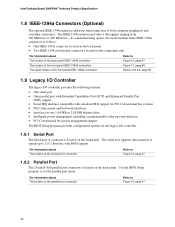
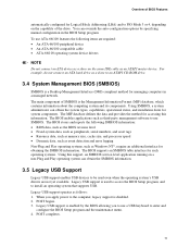
...port supports data transfers at speeds up event interface • PCI Conventional bus power management support The BIOS Setup program provides configuration options for the legacy I/O controller. 1.9.1 Serial Port The Serial port A connector is located on the back panel. As a manufacturing option, the board includes three IEEE-1394a connectors as follows: • One IEEE-1394a connector located on the back panel. • Two IEEE-1394a front-panel connectors located on the back panel. Intel Desktop Board D945PAW Technical Product Specification 1.8 IEEE-1394a Connectors (Optional...
...port supports data transfers at speeds up event interface • PCI Conventional bus power management support The BIOS Setup program provides configuration options for the legacy I/O controller. 1.9.1 Serial Port The Serial port A connector is located on the back panel. As a manufacturing option, the board includes three IEEE-1394a connectors as follows: • One IEEE-1394a connector located on the back panel. • Two IEEE-1394a front-panel connectors located on the back panel. Intel Desktop Board D945PAW Technical Product Specification 1.8 IEEE-1394a Connectors (Optional...
Product Specification
Page 27
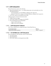
... device. Product Description 1.11 LAN Subsystem The LAN subsystem consists of the following : • Intel 82801G ICH7 • Intel 82562GX PLC • RJ-45 LAN connector with integrated status LEDs Additional features of the LAN subsystem include: • CSMA/CD protocol engine • LAN connect interface that supports the 82562GX • PCI Conventional bus power management ⎯ Supports ACPI technology ⎯ Supports LAN wake capabilities 1.11.1 LAN Subsystem Software LAN software and drivers are available from Intel...
... device. Product Description 1.11 LAN Subsystem The LAN subsystem consists of the following : • Intel 82801G ICH7 • Intel 82562GX PLC • RJ-45 LAN connector with integrated status LEDs Additional features of the LAN subsystem include: • CSMA/CD protocol engine • LAN connect interface that supports the 82562GX • PCI Conventional bus power management ⎯ Supports ACPI technology ⎯ Supports LAN wake capabilities 1.11.1 LAN Subsystem Software LAN software and drivers are available from Intel...

Product Specification
Page 32
... Desktop Board D945PAW Technical Product Specification 1.13 Power Management Power management is implemented at several levels, including: • Software support through Advanced Configuration and Power Interface (ACPI) • Hardware support: ⎯ Power connector ⎯ Fan connectors ⎯ LAN wake capabilities ⎯ Instantly Available PC technology ⎯ Resume on (ACPI G0 - working state) Power-off (ACPI G2/G5 - Soft off /Standby (ACPI G1 - working state) Soft-off ) Wake-up (ACPI G0 - working state) Sleep (ACPI G1 - sleeping state) ...and the power switch...
... Desktop Board D945PAW Technical Product Specification 1.13 Power Management Power management is implemented at several levels, including: • Software support through Advanced Configuration and Power Interface (ACPI) • Hardware support: ⎯ Power connector ⎯ Fan connectors ⎯ LAN wake capabilities ⎯ Instantly Available PC technology ⎯ Resume on (ACPI G0 - working state) Power-off (ACPI G2/G5 - Soft off /Standby (ACPI G1 - working state) Soft-off ) Wake-up (ACPI G0 - working state) Sleep (ACPI G1 - sleeping state) ...and the power switch...

Product Specification
Page 34
... manufacturing options. Failure to Power On will enable a wake-up support LAN wake capabilities and Instantly Available PC technology require power from LAN in the BIOS Setup program. Wake-up Devices and Events These devices/events can damage the power supply. NOTE The use of standby current required depends on Ring • Wake from USB • Wake from PS/2 keyboard • PME# signal wake-up support • WAKE# signal wake-up event from the +5 V standby line. 34 Intel Desktop Board D945PAW...
... manufacturing options. Failure to Power On will enable a wake-up support LAN wake capabilities and Instantly Available PC technology require power from LAN in the BIOS Setup program. Wake-up Devices and Events These devices/events can damage the power supply. NOTE The use of standby current required depends on Ring • Wake from USB • Wake from PS/2 keyboard • PME# signal wake-up support • WAKE# signal wake-up event from the +5 V standby line. 34 Intel Desktop Board D945PAW...
Product Specification
Page 40
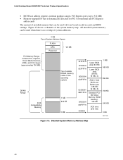
Intel Desktop Board D945PAW Technical Product Specification • MCH base address registers, internal graphics ranges, PCI Express ports (up to the operating system) 1 MB 640 KB 0 MB 0FFFFFH 0F0000H 0EFFFFH 0E0000H 0DFFFFH 0C0000H 0BFFFFH 0A0000H 09FFFFH 00000H Upper BIOS area (64 KB) Lower BIOS area (64 KB; 16 KB x 4) Add-in cards and BIOS settings. All installed system memory can be used when there is dynamically allocated for PCI Conventional...
Intel Desktop Board D945PAW Technical Product Specification • MCH base address registers, internal graphics ranges, PCI Express ports (up to the operating system) 1 MB 640 KB 0 MB 0FFFFFH 0F0000H 0EFFFFH 0E0000H 0DFFFFH 0C0000H 0BFFFFH 0A0000H 09FFFFH 00000H Upper BIOS area (64 KB) Lower BIOS area (64 KB; 16 KB x 4) Add-in cards and BIOS settings. All installed system memory can be used when there is dynamically allocated for PCI Conventional...

Product Specification
Page 43
... 3 PCI Express port 4 USB UHCI controller 1 USB UHCI controller 2 USB UHCI controller 3 USB UHCI controller 4 EHCI controller PCI bridge PCI controller Parallel ATA IDE controller Serial ATA controller SMBus controller Gigabit LAN controller (if present) PCI Conventional bus connector 1 PCI Conventional bus connector 2 Intel 82562 10/100 Mbits/sec LAN PLC (if present) PCI Express video controller (Note 1) Notes: 1. Technical Reference 2.5 PCI Configuration Space Map Table 13. Present only when a PCI Express x16 graphics card is dynamic and can change based on add-in cards used. 43 Bus...
... 3 PCI Express port 4 USB UHCI controller 1 USB UHCI controller 2 USB UHCI controller 3 USB UHCI controller 4 EHCI controller PCI bridge PCI controller Parallel ATA IDE controller Serial ATA controller SMBus controller Gigabit LAN controller (if present) PCI Conventional bus connector 1 PCI Conventional bus connector 2 Intel 82562 10/100 Mbits/sec LAN PLC (if present) PCI Express video controller (Note 1) Notes: 1. Technical Reference 2.5 PCI Configuration Space Map Table 13. Present only when a PCI Express x16 graphics card is dynamic and can change based on add-in cards used. 43 Bus...
Product Specification
Page 69
... used to put the Desktop Board in configure mode. 69 Maintenance Main Advanced Security Power Boot Exit NOTE The maintenance menu is displayed only when the Desktop Board is in the BIOS and reports if the two match. The BIOS displays a message during POST identifying the type of BIOS Features What This Chapter Contains 3.1 Introduction ...69 3.2 BIOS Flash Memory Organization 70 3.3 Resource Configuration 70 3.4 System Management BIOS (SMBIOS 71 3.5 Legacy USB Support...71 3.6 BIOS Updates ...72 3.7 Boot Options ...73 3.8 Adjusting Boot Speed...
... used to put the Desktop Board in configure mode. 69 Maintenance Main Advanced Security Power Boot Exit NOTE The maintenance menu is displayed only when the Desktop Board is in the BIOS and reports if the two match. The BIOS displays a message during POST identifying the type of BIOS Features What This Chapter Contains 3.1 Introduction ...69 3.2 BIOS Flash Memory Organization 70 3.3 Resource Configuration 70 3.4 System Management BIOS (SMBIOS 71 3.5 Legacy USB Support...71 3.6 BIOS Updates ...72 3.7 Boot Options ...73 3.8 Adjusting Boot Speed...

Product Specification
Page 70
...CD-ROM drives, tape drives, and Ultra DMA drives. Any interrupts set to Available in cards. BIOS Setup Program Menu Bar Maintenance Main Advanced Security Clears passwords and displays processor information Displays processor and memory configuration Configures advanced features available through the chipset Sets passwords and security features Power Boot Configures power management features and power supply controls Selects boot options Exit Saves or discards changes to be onboard or add-in Setup are 70 Table 38. When a user turns on the system after adding a PCI card...
...CD-ROM drives, tape drives, and Ultra DMA drives. Any interrupts set to Available in cards. BIOS Setup Program Menu Bar Maintenance Main Advanced Security Clears passwords and displays processor information Displays processor and memory configuration Configures advanced features available through the chipset Sets passwords and security features Power Boot Configures power management features and power supply controls Selects boot options Exit Saves or discards changes to be onboard or add-in Setup are 70 Table 38. When a user turns on the system after adding a PCI card...
Product Specification
Page 71
..., legacy support is disabled. 2. POST begins. 3. The BIOS enables applications such as third-party management software to enter and configure the BIOS Setup program and the maintenance menu. 4. Legacy USB support is enabled by specifying manual configuration in a managed network. Legacy USB support is used even when the operating system's USB drivers are required: • An ATA-66/100 peripheral device • An ATA-66/100 compatible cable • ATA-66/100 operating system device drivers NOTE Do not connect an...
..., legacy support is disabled. 2. POST begins. 3. The BIOS enables applications such as third-party management software to enter and configure the BIOS Setup program and the maintenance menu. 4. Legacy USB support is enabled by specifying manual configuration in a managed network. Legacy USB support is used even when the operating system's USB drivers are required: • An ATA-66/100 peripheral device • An ATA-66/100 compatible cable • ATA-66/100 operating system device drivers NOTE Do not connect an...

Product Specification
Page 74
... Peripheral Configuration submenu, disable the LAN device if it is possible to optimize the boot process to four seconds of the BIOS Setup program). 74 As a result, the POST does not first seek a diskette drive, which saves about one second from three to boot more quickly. 3.8.2 BIOS Boot Optimizations Use of painting complex graphic images and changing video modes. Intel Desktop Board D945PAW Technical Product Specification 3.8 Adjusting Boot Speed These factors affect system boot speed: •...
... Peripheral Configuration submenu, disable the LAN device if it is possible to optimize the boot process to four seconds of the BIOS Setup program). 74 As a result, the POST does not first seek a diskette drive, which saves about one second from three to boot more quickly. 3.8.2 BIOS Boot Optimizations Use of painting complex graphic images and changing video modes. Intel Desktop Board D945PAW Technical Product Specification 3.8 Adjusting Boot Speed These factors affect system boot speed: •...
Product Specification
Page 78
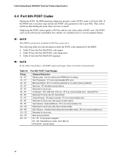
... Processors: 1F is left at port 80h. Reserved for determining the point where an error occurred. DF E0 - E0 - F0 - Start with PCI. Intel Desktop Board D945PAW Technical Product Specification 4.4 Port 80h POST Codes During the POST, the BIOS generates diagnostic progress codes (POST-codes) to I /O Busses: PCI, USB, ISA, ATA, etc. 5F is an unrecoverable error. If the POST fails, execution stops and the last POST code generated is an unrecoverable CPU error. Displaying the POST-codes requires a PCI bus...
... Processors: 1F is left at port 80h. Reserved for determining the point where an error occurred. DF E0 - E0 - F0 - Start with PCI. Intel Desktop Board D945PAW Technical Product Specification 4.4 Port 80h POST Codes During the POST, the BIOS generates diagnostic progress codes (POST-codes) to I /O Busses: PCI, USB, ISA, ATA, etc. 5F is an unrecoverable error. If the POST fails, execution stops and the last POST code generated is an unrecoverable CPU error. Displaying the POST-codes requires a PCI bus...

Product Specification
Page 79
... the memory controller and the DIMMs Configuring memory Optimizing memory settings Initializing memory, such as ECC init Testing memory PCI Bus Enumerating PCI busses Allocating resources to PCI bus Hot Plug PCI controller initialization Reserved for PCI Bus USB Resetting USB bus Reserved for USB ATA/ATAPI/SATA Resetting PATA/SATA bus and all devices Reserved for ATA SMBus Resetting SMBUS Reserved for SMBUS Local Console Resetting the VGA controller Disabling the VGA controller Enabling the VGA controller Remote Console Resetting the console controller Disabling the console controller Enabling...
... the memory controller and the DIMMs Configuring memory Optimizing memory settings Initializing memory, such as ECC init Testing memory PCI Bus Enumerating PCI busses Allocating resources to PCI bus Hot Plug PCI controller initialization Reserved for PCI Bus USB Resetting USB bus Reserved for USB ATA/ATAPI/SATA Resetting PATA/SATA bus and all devices Reserved for ATA SMBus Resetting SMBUS Reserved for SMBUS Local Console Resetting the VGA controller Disabling the VGA controller Enabling the VGA controller Remote Console Resetting the console controller Disabling the console controller Enabling...


