
Product Specification
Page 6
... PCI IDE Support 63 3.4 System Management BIOS (SMBIOS 63 3.5 Legacy USB Support 64 3.6 BIOS Updates 65 3.6.1 Language Support 65 3.6.2 Custom Splash Screen 66 3.7 BIOS Recovery 66 3.8 Boot Options 67 3.8.1 Optical Drive Boot 67 3.8.2 Network Boot 67 3.8.3 Booting Without Attached Devices 67 3.8.4 Changing the Default Boot Device During POST 67 3.9 Adjusting Boot Speed 68 3.9.1 Peripheral Selection and Configuration 68 3.9.2 BIOS Boot Optimizations 68 3.10 BIOS Security Features 69 4 Error Messages and Beep Codes 4.1 Speaker 71 4.2 BIOS Beep Codes 71 4.3 Front-panel Power LED...
... PCI IDE Support 63 3.4 System Management BIOS (SMBIOS 63 3.5 Legacy USB Support 64 3.6 BIOS Updates 65 3.6.1 Language Support 65 3.6.2 Custom Splash Screen 66 3.7 BIOS Recovery 66 3.8 Boot Options 67 3.8.1 Optical Drive Boot 67 3.8.2 Network Boot 67 3.8.3 Booting Without Attached Devices 67 3.8.4 Changing the Default Boot Device During POST 67 3.9 Adjusting Boot Speed 68 3.9.1 Peripheral Selection and Configuration 68 3.9.2 BIOS Boot Optimizations 68 3.10 BIOS Security Features 69 4 Error Messages and Beep Codes 4.1 Speaker 71 4.2 BIOS Beep Codes 71 4.3 Front-panel Power LED...

Product Specification
Page 7
... Front Panel Header 50 12. Front Panel Header 50 23. Alternate Front Panel Power LED Header 51 26. BIOS Setup Configuration Jumper Settings 54 27. Localized High Temperature Zones 58 Tables 1. Wake-up Devices and Events 32 9. S/PDIF Header 47 20. Processor Core Power Connector 49 21. States for Intel HD Audio 47 17. LAN Connector LED Locations 27 6. Serial Port Header 46 13. Main Power Connector 49 22. Fan Header Current Capability 57 vii Memory Channel Configuration and DIMM Configuration 17 4. Location of Pressing the Power Switch 30 7. LAN Connector LED...
... Front Panel Header 50 12. Front Panel Header 50 23. Alternate Front Panel Power LED Header 51 26. BIOS Setup Configuration Jumper Settings 54 27. Localized High Temperature Zones 58 Tables 1. Wake-up Devices and Events 32 9. S/PDIF Header 47 20. Processor Core Power Connector 49 21. States for Intel HD Audio 47 17. LAN Connector LED Locations 27 6. Serial Port Header 46 13. Main Power Connector 49 22. Fan Header Current Capability 57 vii Memory Channel Configuration and DIMM Configuration 17 4. Location of Pressing the Power Switch 30 7. LAN Connector LED...
Product Specification
Page 8
... Keys 62 33. Front-panel Power LED Blink Codes 72 38. Lead-Free Board Markings 84 44. Thermal Considerations for BIOS Recovery 66 34. BIOS Setup Program Menu Bar 62 32. Acceptable Drives/Media Types for Components 59 30. Supervisor and User Password Functions 69 36. Boot Device Menu Options 67 35. Port 80h POST Code Ranges 73 40. Intel Desktop Board DG41TX Technical Product Specification 29. BIOS Error Messages 72 39. Safety Standards 79 43. EMC Regulations 85 45. Intel Desktop Board DG41TX...
... Keys 62 33. Front-panel Power LED Blink Codes 72 38. Lead-Free Board Markings 84 44. Thermal Considerations for BIOS Recovery 66 34. BIOS Setup Program Menu Bar 62 32. Acceptable Drives/Media Types for Components 59 30. Supervisor and User Password Functions 69 36. Boot Device Menu Options 67 35. Port 80h POST Code Ranges 73 40. Intel Desktop Board DG41TX Technical Product Specification 29. BIOS Error Messages 72 39. Safety Standards 79 43. EMC Regulations 85 45. Intel Desktop Board DG41TX...

Product Specification
Page 14
... BIOS and driver updates Tested memory Visit this World Wide Web site: http://www.intel.com/products/motherboard/DG41TX/index.htm http://support.intel.com/support/motherboards/desktop http://www.intel.com/products/motherboard/DG41TX/index.htm http://processormatch.intel.com http://www.intel.com/products/desktop/chipsets/index.htm http://downloadcenter.intel.com http://support.intel.com/support/motherboards/desktop/kr/CS025414.htm 1.4 Processor The board is designed to support processors with specific changes including (but not limited to -date list...
... BIOS and driver updates Tested memory Visit this World Wide Web site: http://www.intel.com/products/motherboard/DG41TX/index.htm http://support.intel.com/support/motherboards/desktop http://www.intel.com/products/motherboard/DG41TX/index.htm http://processormatch.intel.com http://www.intel.com/products/desktop/chipsets/index.htm http://downloadcenter.intel.com http://support.intel.com/support/motherboards/desktop/kr/CS025414.htm 1.4 Processor The board is designed to support processors with specific changes including (but not limited to -date list...

Product Specification
Page 23
... location of the battery. When the computer is plugged in CMOS RAM (for PCI systems • PS/2-style keyboard/mouse interfaces • One parallel port back panel connector • Intelligent power management, including a programmable wake-up to ± 13 minutes/year at speeds up event interface • PCI power management support The BIOS Setup program provides configuration options for the I /O controller provides the following features: • One serial port header • Serial IRQ interface compatible with serialized...
... location of the battery. When the computer is plugged in CMOS RAM (for PCI systems • PS/2-style keyboard/mouse interfaces • One parallel port back panel connector • Intelligent power management, including a programmable wake-up to ± 13 minutes/year at speeds up event interface • PCI power management support The BIOS Setup program provides configuration options for the I /O controller provides the following features: • One serial port header • Serial IRQ interface compatible with serialized...
Product Specification
Page 26
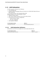
.../1000 Mbits/s Ethernet LAN connectivity • RJ-45 LAN connector with integrated status LEDs Additional features of the LAN subsystem include: • CSMA/CD protocol engine • LAN connect interface between ICH7 and the LAN controller • Conventional PCI bus power management ⎯ ACPI technology support ⎯ LAN wake capabilities • LAN subsystem software For information about Obtaining LAN software and drivers Refer to http://downloadcenter.intel.com 1.11.1 LAN Subsystem Software LAN software and drivers are available from...
.../1000 Mbits/s Ethernet LAN connectivity • RJ-45 LAN connector with integrated status LEDs Additional features of the LAN subsystem include: • CSMA/CD protocol engine • LAN connect interface between ICH7 and the LAN controller • Conventional PCI bus power management ⎯ ACPI technology support ⎯ LAN wake capabilities • LAN subsystem software For information about Obtaining LAN software and drivers Refer to http://downloadcenter.intel.com 1.11.1 LAN Subsystem Software LAN software and drivers are available from...

Product Specification
Page 61
... menu bar is powered-up, the BIOS compares the CPU version and the microcode version in the Serial Peripheral Interface Flash Memory (SPI Flash) and can be updated using a disk-based program. The BIOS displays a message during POST identifying the type of BIOS Features 3.1 Introduction The board uses an Intel BIOS that is accessed by pressing the key after the Power-On Self-Test (POST) memory test begins and before the operating system boot begins. When the BIOS Setup configuration jumper is set...
... menu bar is powered-up, the BIOS compares the CPU version and the microcode version in the Serial Peripheral Interface Flash Memory (SPI Flash) and can be updated using a disk-based program. The BIOS displays a message during POST identifying the type of BIOS Features 3.1 Introduction The board uses an Intel BIOS that is accessed by pressing the key after the Power-On Self-Test (POST) memory test begins and before the operating system boot begins. When the BIOS Setup configuration jumper is set...
Product Specification
Page 62
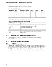
... Interface Flash Memory (SPI Flash) includes an 8 Mbit (1024 KB) flash memory device. 3.3 Resource Configuration 3.3.1 PCI Autoconfiguration The BIOS can automatically configure PCI devices. BIOS Setup Program Menu Bar Maintenance Main Advanced Security Clears passwords and displays processor information Displays processor and memory configuration Configures advanced features available through the chipset Sets passwords and security features Power Boot Configures power management features and power supply controls Selects boot options Exit Saves or discards changes to configure...
... Interface Flash Memory (SPI Flash) includes an 8 Mbit (1024 KB) flash memory device. 3.3 Resource Configuration 3.3.1 PCI Autoconfiguration The BIOS can automatically configure PCI devices. BIOS Setup Program Menu Bar Maintenance Main Advanced Security Clears passwords and displays processor information Displays processor and memory configuration Configures advanced features available through the chipset Sets passwords and security features Power Boot Configures power management features and power supply controls Selects boot options Exit Saves or discards changes to configure...

Product Specification
Page 68
... add-in adapter features, such as logo displays, screen repaints, or mode changes in POST. Intel Desktop Board DG41TX Technical Product Specification 3.9 Adjusting Boot Speed These factors affect system boot speed: • Selecting and configuring peripherals properly • Optimized BIOS boot parameters 3.9.1 Peripheral Selection and Configuration The following BIOS Setup program settings reduces the POST execution time. • In the Boot Menu, set the hard disk drive as the first boot device. Some monitors initialize and communicate with a fast initialization rate...
... add-in adapter features, such as logo displays, screen repaints, or mode changes in POST. Intel Desktop Board DG41TX Technical Product Specification 3.9 Adjusting Boot Speed These factors affect system boot speed: • Selecting and configuring peripherals properly • Optimized BIOS boot parameters 3.9.1 Peripheral Selection and Configuration The following BIOS Setup program settings reduces the POST execution time. • In the Boot Menu, set the hard disk drive as the first boot device. Some monitors initialize and communicate with a fast initialization rate...

Product Specification
Page 73
Displaying the POST codes requires a PCI bus add-in PCI bus connector 1. Table 39. AF B0 - DF Input devices: Keyboard/Mouse. 9F is an unrecoverable error. Reserved for new busses). E0 - FF E0 - F0 - FF: FF processor exception. 73 The POST card can decode the port and display the contents on a medium such as a seven-segment display. Recovery: 3F indicated recovery failure. I /O port 80h. BF C0 - Boot Devices: Includes fixed media and removable media. Boot device selection...
Displaying the POST codes requires a PCI bus add-in PCI bus connector 1. Table 39. AF B0 - DF Input devices: Keyboard/Mouse. 9F is an unrecoverable error. Reserved for new busses). E0 - FF E0 - F0 - FF: FF processor exception. 73 The POST card can decode the port and display the contents on a medium such as a seven-segment display. Recovery: 3F indicated recovery failure. I /O port 80h. BF C0 - Boot Devices: Includes fixed media and removable media. Boot device selection...
Product Specification
Page 76
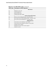
... Legacy Option ROMs Runtime Phase/EFI OS Boot F8 EFI boot service ExitBootServices ( ) has been called F9 EFI runtime service SetVirtualAddressMap ( ) has been called FA EFI runtime service ResetSystem ( ) has been called PEIMs/Recovery 30 Crisis Recovery has initiated per User request 31 Crisis Recovery has initiated by software (corrupt flash) 34 Loading recovery capsule 35 Handing off control to the recovery capsule 3F Unable to recover 76 Intel Desktop Board DG41TX...
... Legacy Option ROMs Runtime Phase/EFI OS Boot F8 EFI boot service ExitBootServices ( ) has been called F9 EFI runtime service SetVirtualAddressMap ( ) has been called FA EFI runtime service ResetSystem ( ) has been called PEIMs/Recovery 30 Crisis Recovery has initiated per User request 31 Crisis Recovery has initiated by software (corrupt flash) 34 Loading recovery capsule 35 Handing off control to the recovery capsule 3F Unable to recover 76 Intel Desktop Board DG41TX...

Product Specification
Page 77
Error Messages and Beep Codes Table 41. Typical Port 80h POST Sequence POST Code Description 21 Initializing a chipset component 22 Reading SPD from memory DIMMs 23 Detecting presence of memory DIMMs 25 Configuring memory 28 Testing memory 34 Loading recovery capsule E4 Entered DXE phase 12 Starting application processor initialization 13 SMM initialization 50 Enumerating PCI busses 51 Allocating resourced to PCI bus 92 Detecting the presence of the keyboard 90 Resetting keyboard 94 Clearing keyboard input...
Error Messages and Beep Codes Table 41. Typical Port 80h POST Sequence POST Code Description 21 Initializing a chipset component 22 Reading SPD from memory DIMMs 23 Detecting presence of memory DIMMs 25 Configuring memory 28 Testing memory 34 Loading recovery capsule E4 Entered DXE phase 12 Starting application processor initialization 13 SMM initialization 50 Enumerating PCI busses 51 Allocating resourced to PCI bus 92 Detecting the presence of the keyboard 90 Resetting keyboard 94 Clearing keyboard input...

English Product Guide
Page 3
... manual: CAUTION Cautions warn the user about board layout, component installation, BIOS update, and regulatory requirements for technically qualified personnel. iii It is intended for Intel® Desktop Board DG41TX. Use Only for Intended Applications All Intel Desktop Boards are evaluated as Information Technology Equipment (I.T.E.) for use in personal computers (PC) for general audiences. NOTE Notes call attention to hardware or loss of product features 2 Installing and Replacing Desktop Board Components: instructions...
... manual: CAUTION Cautions warn the user about board layout, component installation, BIOS update, and regulatory requirements for technically qualified personnel. iii It is intended for Intel® Desktop Board DG41TX. Use Only for Intended Applications All Intel Desktop Boards are evaluated as Information Technology Equipment (I.T.E.) for use in personal computers (PC) for general audiences. NOTE Notes call attention to hardware or loss of product features 2 Installing and Replacing Desktop Board Components: instructions...
English Product Guide
Page 6
...Drive Cable 46 Connecting to Internal Headers 47 Front Panel HD Audio Header 48 HD Audio Link Header 48 Serial Port Header 49 USB 2.0 Headers 49 Chassis Intrusion Header 50 Front Panel Header 50 Alternate Front Panel Power LED Header 50 S/PDIF Header 51 Connecting to the Audio System 51 Connecting Chassis Fan and Power Supply Cables 52 Chassis Fan Cables 52 Power Supply Cables 53 Setting the BIOS Configuration Jumper 54 Clearing Passwords in the BIOS Setup Program 55 Replacing the Battery 56 3 Updating the BIOS Updating the BIOS with the Intel® Express BIOS Update Utility...
...Drive Cable 46 Connecting to Internal Headers 47 Front Panel HD Audio Header 48 HD Audio Link Header 48 Serial Port Header 49 USB 2.0 Headers 49 Chassis Intrusion Header 50 Front Panel Header 50 Alternate Front Panel Power LED Header 50 S/PDIF Header 51 Connecting to the Audio System 51 Connecting Chassis Fan and Power Supply Cables 52 Chassis Fan Cables 52 Power Supply Cables 53 Setting the BIOS Configuration Jumper 54 Clearing Passwords in the BIOS Setup Program 55 Replacing the Battery 56 3 Updating the BIOS Updating the BIOS with the Intel® Express BIOS Update Utility...

English Product Guide
Page 10
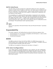
... panel USB headers • Four Serial ATA (SATA) channels (3.0 Gb/s) via ICH7 • One dual-channel Parallel ATA (PATA) interface • One flexible diskette interface • Intel® Platform Innovation Framework for EFI • 16 Mb symmetrical flash memory device • Support for SMBIOS • Intel® Rapid BIOS Boot • Intel® Express BIOS Update • Support for Advanced Configuration and Power Interface (ACPI) • Suspend to RAM (STR) • Wake on USB, PCI Express, PCI, LAN, PS/2, front panel, and serial port...
... panel USB headers • Four Serial ATA (SATA) channels (3.0 Gb/s) via ICH7 • One dual-channel Parallel ATA (PATA) interface • One flexible diskette interface • Intel® Platform Innovation Framework for EFI • 16 Mb symmetrical flash memory device • Support for SMBIOS • Intel® Rapid BIOS Boot • Intel® Express BIOS Update • Support for Advanced Configuration and Power Interface (ACPI) • Suspend to RAM (STR) • Wake on USB, PCI Express, PCI, LAN, PS/2, front panel, and serial port...
English Product Guide
Page 21
... cards) • One PCI Express 1.1 x1 connector • Two PCI bus connectors BIOS The BIOS provides the Power-On Self-Test (POST), the BIOS Setup program, the PCI/PCI Express auto-configuration utilities, and the video BIOS. One device can be installed on each port for a maximum of 3.0 Gb/s on each port. The SATA controller supports IDE and AHCI configuration and can override the auto-configuration options by following expansion slots: • One PCI Express 2.0 x16 connector (compatible with a theoretical maximum transfer rate of four SATA devices. The BIOS can be updated...
... cards) • One PCI Express 1.1 x1 connector • Two PCI bus connectors BIOS The BIOS provides the Power-On Self-Test (POST), the BIOS Setup program, the PCI/PCI Express auto-configuration utilities, and the video BIOS. One device can be installed on each port for a maximum of 3.0 Gb/s on each port. The SATA controller supports IDE and AHCI configuration and can override the auto-configuration options by following expansion slots: • One PCI Express 2.0 x16 connector (compatible with a theoretical maximum transfer rate of four SATA devices. The BIOS can be updated...

English Product Guide
Page 24
... a wake-up signal that can adjust the fan speed according to thermal conditions. • All fan headers have a +12 V DC connection. • The system fan headers support auto-detection for 4-pin and 3-pin chassis fans. Intel Desktop Board DG41TX Product Guide Hardware Support Power Connectors ATX12V-compliant power supplies can turn off when the computer is in the ACPI S3, S4, or S5 state. • All fan headers support closed-loop fan control that powers up the computer. 24 The Desktop Board has two power connectors. Failure...
... a wake-up signal that can adjust the fan speed according to thermal conditions. • All fan headers have a +12 V DC connection. • The system fan headers support auto-detection for 4-pin and 3-pin chassis fans. Intel Desktop Board DG41TX Product Guide Hardware Support Power Connectors ATX12V-compliant power supplies can turn off when the computer is in the ACPI S3, S4, or S5 state. • All fan headers support closed-loop fan control that powers up the computer. 24 The Desktop Board has two power connectors. Failure...

English Product Guide
Page 29
... workstation using and modifying electronic equipment. 2 Installing and Replacing Desktop Board Components This chapter tells you how to: • Install the I/O shield • Install and remove the Desktop Board • Install and remove a processor • Install and remove memory • Install and remove a PCI Express x16 card • Connect PATA (IDE) and SATA cables • Connect the flexible diskette drive cable • Connect to the internal headers • Connect to record information about your computer, such as model, serial numbers, installed options, and configuration...
... workstation using and modifying electronic equipment. 2 Installing and Replacing Desktop Board Components This chapter tells you how to: • Install the I/O shield • Install and remove the Desktop Board • Install and remove a processor • Install and remove memory • Install and remove a PCI Express x16 card • Connect PATA (IDE) and SATA cables • Connect the flexible diskette drive cable • Connect to the internal headers • Connect to record information about your computer, such as model, serial numbers, installed options, and configuration...

English Product Guide
Page 55
... Replacing Desktop Board Components Table 14. Configure (2-3) After the Power-On Self-Test (POST) runs, the BIOS displays the Maintenance Menu. Turn off all peripheral devices connected to clear passwords. Disconnect the computer's power cord from the AC power source (wall outlet or power adapter). 3. Replace the cover, plug in the computer and the configuration jumper block is set to normal mode. 1. Use the arrow keys to boot. 7. Select Yes and press . Jumper Settings for the BIOS Setup Program Modes Jumper Setting Mode Normal (default...
... Replacing Desktop Board Components Table 14. Configure (2-3) After the Power-On Self-Test (POST) runs, the BIOS displays the Maintenance Menu. Turn off all peripheral devices connected to clear passwords. Disconnect the computer's power cord from the AC power source (wall outlet or power adapter). 3. Replace the cover, plug in the computer and the configuration jumper block is set to normal mode. 1. Use the arrow keys to boot. 7. Select Yes and press . Jumper Settings for the BIOS Setup Program Modes Jumper Setting Mode Normal (default...

English Product Guide
Page 63
... last Express BIOS Update window. 5. Go to the DG41TX page. 3 Updating the BIOS The BIOS Setup program can access the BIOS Setup program by either using the Intel Express BIOS Update utility or the Intel® Flash Memory Update Utility, and how to a removable USB device. This step is required. To update the BIOS with the Intel® Express BIOS Update Utility With the Intel Express BIOS Update utility you how to update the BIOS by pressing the key after the Power-On Self-Test (POST) memory test begins and before the operating system boot...
... last Express BIOS Update window. 5. Go to the DG41TX page. 3 Updating the BIOS The BIOS Setup program can access the BIOS Setup program by either using the Intel Express BIOS Update utility or the Intel® Flash Memory Update Utility, and how to a removable USB device. This step is required. To update the BIOS with the Intel® Express BIOS Update Utility With the Intel Express BIOS Update utility you how to update the BIOS by pressing the key after the Power-On Self-Test (POST) memory test begins and before the operating system boot...


