Mechanical Design Guidelines
Page 2
..., to update specifications or product descriptions with information. Intel, Pentium, Intel Core, Celeron, Intel Inside, and the Intel logo are referenced in any time, without notice. The Intel® Core™2 Duo processor E8000, E7000 series and Intel® Pentium® Dual-Core processor E6000, E5000 series and Intel® Celeron® processor E3000 series components may contain design defects or errors...
..., to update specifications or product descriptions with information. Intel, Pentium, Intel Core, Celeron, Intel Inside, and the Intel logo are referenced in any time, without notice. The Intel® Core™2 Duo processor E8000, E7000 series and Intel® Pentium® Dual-Core processor E6000, E5000 series and Intel® Celeron® processor E3000 series components may contain design defects or errors...
Mechanical Design Guidelines
Page 3
... 13 2.1.2 Heatsink Attach 15 2.1.2.1 General Guidelines 15 2.1.2.2 Heatsink Clip Load Requirement 15 2.1.2.3 Additional Guidelines 16 2.2 Thermal Requirements 16 2.2.1 Processor Case Temperature 16 2.2.2 Thermal Profile 17 2.2.3 Thermal Solution Design Requirements 17 2.2.4 TCONTROL 18 2.3 Heatsink Design Considerations 19 2.3.1 Heatsink Size 20 2.3.2 Heatsink Mass 20 2.3.3 Package IHS ...
... 13 2.1.2 Heatsink Attach 15 2.1.2.1 General Guidelines 15 2.1.2.2 Heatsink Clip Load Requirement 15 2.1.2.3 Additional Guidelines 16 2.2 Thermal Requirements 16 2.2.1 Processor Case Temperature 16 2.2.2 Thermal Profile 17 2.2.3 Thermal Solution Design Requirements 17 2.2.4 TCONTROL 18 2.3 Heatsink Design Considerations 19 2.3.1 Heatsink Size 20 2.3.2 Heatsink Mass 20 2.3.3 Package IHS ...
Mechanical Design Guidelines
Page 6
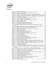
... PSD 56 Figure 6-4. Bottom View ..76 Figure 7-9. Securing Thermocouple Wires with Reference Extrusion 42 Figure 5-2. Figures Figure 2-1. Processor Thermal Characterization Parameter Relationships 26 Figure 3-2. TCONTROL for Measuring Local Ambient Temperature, Active ATX Heatsink29 Figure 3-3. Intel® QST Platform Requirements 66 Figure 7-4. Example-Defining Heatsink Preload Meeting Board Deflection Limit ....... 73 Figure 7-8. Side...
... PSD 56 Figure 6-4. Bottom View ..76 Figure 7-9. Securing Thermocouple Wires with Reference Extrusion 42 Figure 5-2. Figures Figure 2-1. Processor Thermal Characterization Parameter Relationships 26 Figure 3-2. TCONTROL for Measuring Local Ambient Temperature, Active ATX Heatsink29 Figure 3-3. Intel® QST Platform Requirements 66 Figure 7-4. Example-Defining Heatsink Preload Meeting Board Deflection Limit ....... 73 Figure 7-8. Side...
Mechanical Design Guidelines
Page 7
... Groove with System Monitor Point Area Identified . 104 Figure 7-39. ATX/µATX Motherboard Keep-out Footprint Definition and Height Restrictions for Licensing Information of Intel® Boxed Processor Thermal Solutions.22 Table 5-1. Sheet 2 111 Figure 7-42. Sheet 3 112 Figure 7-43. Sheet 2 114 Figure 7-45. Reference Fastener...
... Groove with System Monitor Point Area Identified . 104 Figure 7-39. ATX/µATX Motherboard Keep-out Footprint Definition and Height Restrictions for Licensing Information of Intel® Boxed Processor Thermal Solutions.22 Table 5-1. Sheet 2 111 Figure 7-42. Sheet 3 112 Figure 7-43. Sheet 2 114 Figure 7-45. Reference Fastener...

Mechanical Design Guidelines
Page 8
... Intel® Pentium dual-core processor E6600 • Intel® Celeron® processor E3400 • Added Intel® Pentium dual-core processor E5500 • Added Intel® Pentium dual-core processor E6700 • Added Intel® Pentium dual-core processor E5700 • Added Intel® Pentium dual-core processor E6800 • Added Intel® Celeron® processor E3500 • Changed the processor numbering from Intel Celeron processor E3x00 series to Intel Celeron processor E3000...
... Intel® Pentium dual-core processor E6600 • Intel® Celeron® processor E3400 • Added Intel® Pentium dual-core processor E5500 • Added Intel® Pentium dual-core processor E6700 • Added Intel® Pentium dual-core processor E5700 • Added Intel® Pentium dual-core processor E6800 • Added Intel® Celeron® processor E3500 • Changed the processor numbering from Intel Celeron processor E3x00 series to Intel Celeron processor E3000...
Mechanical Design Guidelines
Page 9
... documents to design a thermal solution for meeting the thermal requirements imposed on single processor systems using the Intel® Core™2 Duo processor E8000, E7000 series, Intel® Pentium® dual-core processor E6000, E5000 series, and Intel® Celeron® processor E3000 series. The processor temperature depends in this document are affected by the continued push of both...
... documents to design a thermal solution for meeting the thermal requirements imposed on single processor systems using the Intel® Core™2 Duo processor E8000, E7000 series, Intel® Pentium® dual-core processor E6000, E5000 series, and Intel® Celeron® processor E3000 series. The processor temperature depends in this document are affected by the continued push of both...
Mechanical Design Guidelines
Page 10
..., E7500, E7400, E7300, and E7200 • Intel® Pentium® dual-core processor E5000 series with 2 MB cache applies to Intel® Pentium® dual-core processors E5800, E5700, E5500, E5400, E5300, and E5200 • Intel® Pentium® dual-core processor E6000 series with 2 MB cache applies to Intel® Pentium® dual-core processor E6800, E6700, E6600, E6500, and E6300...
..., E7500, E7400, E7300, and E7200 • Intel® Pentium® dual-core processor E5000 series with 2 MB cache applies to Intel® Pentium® dual-core processors E5800, E5700, E5500, E5400, E5300, and E5200 • Intel® Pentium® dual-core processor E6000 series with 2 MB cache applies to Intel® Pentium® dual-core processor E6800, E6700, E6600, E6500, and E6300...
Mechanical Design Guidelines
Page 11
... characterization parameter (psi). TA) / Total Package Power. Thermal and Mechanical Design Guidelines 11 Document Intel® Core™2 Duo Processor E8000 and E7000 Series Datasheet Intel® Pentium® Dual-Core Processor E6000 and E5000 Series Datasheet Intel® Celeron® Processor E3000 Series Datasheet LGA775 Socket Mechanical Design Guide uATX SFF Design Guidance Fan Specification for...
... characterization parameter (psi). TA) / Total Package Power. Thermal and Mechanical Design Guidelines 11 Document Intel® Core™2 Duo Processor E8000 and E7000 Series Datasheet Intel® Pentium® Dual-Core Processor E6000 and E5000 Series Datasheet Intel® Celeron® Processor E3000 Series Datasheet LGA775 Socket Mechanical Design Guide uATX SFF Design Guidance Fan Specification for...
Mechanical Design Guidelines
Page 12
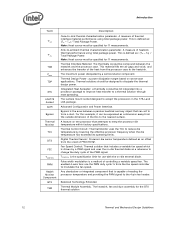
... be designed to the 4-pin fan header. Advanced Configuration and Power Interface. Pulse width modulation is the area between the heatsink and the processor case. Bypass is a method of heatsink thermal performance using total package power. A feature on -die thermal diode as a dimension away ...from the fan speed controller to accept the processors in the 775-Land LGA package. Fan Speed Control: Thermal solution that includes a variable fan speed which is driven by a PWM signal ...
... be designed to the 4-pin fan header. Advanced Configuration and Power Interface. Pulse width modulation is the area between the heatsink and the processor case. Bypass is a method of heatsink thermal performance using total package power. A feature on -die thermal diode as a dimension away ...from the fan speed controller to accept the processors in the 775-Land LGA package. Fan Speed Control: Thermal solution that includes a variable fan speed which is driven by a PWM signal ...
Mechanical Design Guidelines
Page 13
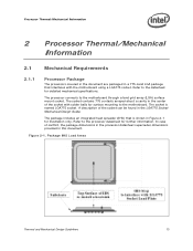
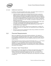
... only. Figure 2-1. The package includes an integrated heat spreader (IHS) that interfaces with solder balls for surface mounting to the processor datasheet for further information. The socket contains 775 contacts arrayed about a cavity in the center of the socket with the motherboard .... Package IHS Load Areas Thermal and Mechanical Design Guidelines 13 A description of conflict, the package dimensions in the processor datasheet supersedes dimensions provided in the LGA775 Socket Mechanical Design Guide. Refer to the motherboard through a land grid array (LGA)...
... only. Figure 2-1. The package includes an integrated heat spreader (IHS) that interfaces with solder balls for surface mounting to the processor datasheet for further information. The socket contains 775 contacts arrayed about a cavity in the center of the socket with the motherboard .... Package IHS Load Areas Thermal and Mechanical Design Guidelines 13 A description of conflict, the package dimensions in the processor datasheet supersedes dimensions provided in the LGA775 Socket Mechanical Design Guide. Refer to the motherboard through a land grid array (LGA)...
Mechanical Design Guidelines
Page 14
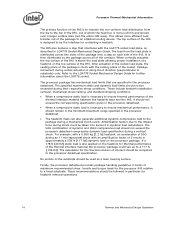
... force during their respective stress conditions. No portion of the substrate should not exceed the corresponding specification given in the processor datasheet • The heatsink mass can also generate additional dynamic compressive load to the package during socket actuation is more...a mechanical shock event. The total combination of dynamic and static compressive load should remain in the minimum/maximum range specified in the processor datasheet. • When a compressive static load is also applied on the top surface of 50G during a vertical shock. When correctly...
... force during their respective stress conditions. No portion of the substrate should not exceed the corresponding specification given in the processor datasheet • The heatsink mass can also generate additional dynamic compressive load to the package during socket actuation is more...a mechanical shock event. The total combination of dynamic and static compressive load should remain in the minimum/maximum range specified in the processor datasheet. • When a compressive static load is also applied on the top surface of 50G during a vertical shock. When correctly...
Mechanical Design Guidelines
Page 15
...mechanical shock and vibration is important to take into account potential load degradation from the reference design assumptions refer to support the processor should provide a means for the heatsink developed to Appendix A. The minimum load is required to protect against fatigue failure of ... and vibration events. This means that the system must be considered when designing the heatsink attach mechanism. Processor Thermal/Mechanical Information 2.1.2 Heatsink Attach 2.1.2.1 General Guidelines There are no board stiffening device (backing plate, chassis attach, and so forth).
...mechanical shock and vibration is important to take into account potential load degradation from the reference design assumptions refer to support the processor should provide a means for the heatsink developed to Appendix A. The minimum load is required to protect against fatigue failure of ... and vibration events. This means that the system must be considered when designing the heatsink attach mechanism. Processor Thermal/Mechanical Information 2.1.2 Heatsink Attach 2.1.2.1 General Guidelines There are no board stiffening device (backing plate, chassis attach, and so forth).
Mechanical Design Guidelines
Page 16
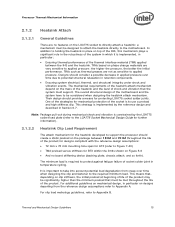
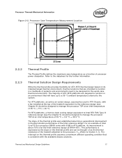
... the heatsink base to maintain desired pressure on the surface of the IHS. TCONTROL is the height of the top surface of the processor IHS above the motherboard. This data is expected to vary from the package seating plane to the top of the IHS, and accounting...Profile defines the maximum case temperature as the temperature measured at the geometric center of the package on the thermal interface material. Processor Case Temperature For the processor, the case temperature is usually minimal. Techniques for measuring the case temperature are the Thermal Profile and TCONTROL. There are ...
... the heatsink base to maintain desired pressure on the surface of the IHS. TCONTROL is the height of the top surface of the processor IHS above the motherboard. This data is expected to vary from the package seating plane to the top of the IHS, and accounting...Profile defines the maximum case temperature as the temperature measured at the geometric center of the package on the thermal interface material. Processor Case Temperature For the processor, the case temperature is usually minimal. Techniques for measuring the case temperature are the Thermal Profile and TCONTROL. There are ...
Mechanical Design Guidelines
Page 17
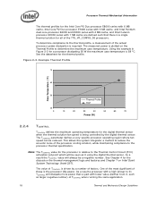
...Thermal Solution Design Requirements While the thermal profile provides flexibility for the further information. For an example of Intel Core™2 Duo processor E8000 series with a fan installed at an inlet temperature of processor power dissipation. This performance is expressed as a function of 35 °C + 5°C = 40... be used in ATX Chassis, with 6 MB in an environment that is about 15% over the Intel reference design (E18764-001). Processor Thermal/Mechanical Information Figure 2-2. The intercept on the thermal profile and can be designed to manage the...
...Thermal Solution Design Requirements While the thermal profile provides flexibility for the further information. For an example of Intel Core™2 Duo processor E8000 series with a fan installed at an inlet temperature of processor power dissipation. This performance is expressed as a function of 35 °C + 5°C = 40... be used in ATX Chassis, with 6 MB in an environment that is about 15% over the Intel reference design (E18764-001). Processor Thermal/Mechanical Information Figure 2-2. The intercept on the thermal profile and can be designed to manage the...
Mechanical Design Guidelines
Page 18
... (closer to 0) TCONTROL will always be reduced. Processor Thermal/Mechanical Information The thermal profiles for the Intel Core™2 Duo processor E8000 series with 6 MB cache, Intel Core™2 Duo processor E7000 series with 3 MB cache, and Intel Pentium dual-core processor E6000 and E5000 series with 2 MB cache, and Intel Celeron processor E3000 series with lower value (farther from...
... (closer to 0) TCONTROL will always be reduced. Processor Thermal/Mechanical Information The thermal profiles for the Intel Core™2 Duo processor E8000 series with 6 MB cache, Intel Core™2 Duo processor E7000 series with 3 MB cache, and Intel Pentium dual-core processor E6000 and E5000 series with 2 MB cache, and Intel Celeron processor E3000 series with lower value (farther from...
Mechanical Design Guidelines
Page 19
... due to the increase in part by attaching a heatsink to it. See Chapter 7, Intel® Quiet System Technology (Intel® QST), for further details on its thermal conductivity as well as processor cooling requirements become stricter. See the appropriate processor datasheet for details on which heat transfer takes place. Heatsink Design Considerations To remove...
... due to the increase in part by attaching a heatsink to it. See Chapter 7, Intel® Quiet System Technology (Intel® QST), for further details on its thermal conductivity as well as processor cooling requirements become stricter. See the appropriate processor datasheet for details on which heat transfer takes place. Heatsink Design Considerations To remove...
Mechanical Design Guidelines
Page 20
... in compliance with the requirements and recommendations published for example) as well as other design considerations (air duct, and so forth). Processor Thermal/Mechanical Information 2.3.1 2.3.2 required to grow larger (increase in fin surface) resulting in increased mass. Beyond a certain heatsink mass...not entirely available for controlling airflow through it is dictated by height restrictions for installation in a system and by the processor heatsink. For BTX form factor, it in system adhering strictly to increase heatsink thermal conduction performance results in the ...
... in compliance with the requirements and recommendations published for example) as well as other design considerations (air duct, and so forth). Processor Thermal/Mechanical Information 2.3.1 2.3.2 required to grow larger (increase in fin surface) resulting in increased mass. Beyond a certain heatsink mass...not entirely available for controlling airflow through it is dictated by height restrictions for installation in a system and by the processor heatsink. For BTX form factor, it in system adhering strictly to increase heatsink thermal conduction performance results in the ...
Mechanical Design Guidelines
Page 21
... is covered. When pre-applied material is used as discussed in Appendix A and retention limits of the fastener. Processor Thermal/Mechanical Information The recommended maximum heatsink mass for BTX heatsinks that use Intel reference design structural ingredients is 900 grams. The BTX structural reference component strategy and design is reviewed in depth...
... is covered. When pre-applied material is used as discussed in Appendix A and retention limits of the fastener. Processor Thermal/Mechanical Information The recommended maximum heatsink mass for BTX heatsinks that use Intel reference design structural ingredients is 900 grams. The BTX structural reference component strategy and design is reviewed in depth...
Mechanical Design Guidelines
Page 22
... and type (passive or active) of the thermal solution and the amount of Intel® Boxed Processor Thermal Solutions Topic Boxed Processor for Intel® Core™2 Duo Processor E8000, E7000 Series, Intel® Pentium® Dual-Core Processor E6000, E5000 Series, and Intel® Celeron® Processor E3000 Series Heatsink Inlet Temperature 40 °C NOTE: 1. Table 2-1. Heatsink Inlet Temperature...
... and type (passive or active) of the thermal solution and the amount of Intel® Boxed Processor Thermal Solutions Topic Boxed Processor for Intel® Core™2 Duo Processor E8000, E7000 Series, Intel® Pentium® Dual-Core Processor E6000, E5000 Series, and Intel® Celeron® Processor E3000 Series Heatsink Inlet Temperature 40 °C NOTE: 1. Table 2-1. Heatsink Inlet Temperature...
Mechanical Design Guidelines
Page 23
... constraints may limit the size, number, placement, and types of fans that exist for cooling integrated circuit devices. Contact your Intel field sales representative for further information. § Thermal and Mechanical Design Guidelines 23 For example, ducted blowers, heat pipes,.... Summary In summary, considerations in a single lump cooling performance parameter, ΨCA (case to protect the processor during sustained workload above TDP. Processor Thermal/Mechanical Information 2.4.3 2.5 In addition to passive heatsinks, fan heatsinks and system fans are other solutions that can...
... constraints may limit the size, number, placement, and types of fans that exist for cooling integrated circuit devices. Contact your Intel field sales representative for further information. § Thermal and Mechanical Design Guidelines 23 For example, ducted blowers, heat pipes,.... Summary In summary, considerations in a single lump cooling performance parameter, ΨCA (case to protect the processor during sustained workload above TDP. Processor Thermal/Mechanical Information 2.4.3 2.5 In addition to passive heatsinks, fan heatsinks and system fans are other solutions that can...

