

User Manual
Page 1
M-414459 Revision H3 01/2014 Copyright © 2014 JET This .pdf document is bookmarked Operating Instructions and Parts Manual 7-inch Horizontal-Vertical Band Saw Model HVBS-7MW JET 427 New Sanford Road LaVergne, Tennessee 37086 Ph.: 800-274-6848 www.jettools.com Part No.
M-414459 Revision H3 01/2014 Copyright © 2014 JET This .pdf document is bookmarked Operating Instructions and Parts Manual 7-inch Horizontal-Vertical Band Saw Model HVBS-7MW JET 427 New Sanford Road LaVergne, Tennessee 37086 Ph.: 800-274-6848 www.jettools.com Part No.
User Manual
Page 2
..., SO THE ABOVE LIMITATION MAY NOT APPLY TO YOU. Motors; Pro-Duty Air Tools 2 Year - Wilton branded products; Manual Hoist Accessories; Hand Tools NOTE: JET, Wilton and Powermatic are used for commercial or industrial purposes default to become inoperable within a reasonable amount of our tools needs service or repair, please contact Technical Service by a 90 day limited warranty against manufacturers' defects. Who is Covered This...
..., SO THE ABOVE LIMITATION MAY NOT APPLY TO YOU. Motors; Pro-Duty Air Tools 2 Year - Wilton branded products; Manual Hoist Accessories; Hand Tools NOTE: JET, Wilton and Powermatic are used for commercial or industrial purposes default to become inoperable within a reasonable amount of our tools needs service or repair, please contact Technical Service by a 90 day limited warranty against manufacturers' defects. Who is Covered This...
User Manual
Page 3
... Page 1.0 Warranty and Service...2 2.0 Table of contents...3 3.0 Safety warnings...4 4.0 About this manual ...5 5.0 Specifications ...6 6.0 Setup and assembly...7 6.1 Shipping contents...7 6.2 Unpacking and clean-up...7 6.3 Assembly ...7 6.4 Vertical cutting plate ...7 6.5 Coolant tank preparation ...8 6.6 Electrical connections...8 6.7 Voltage conversion...9 6.8 Extension cords...9 7.0 Adjustments ...10 7.1 Hydraulic feed selector...10 7.2 Changing blade speed...10 7.3 Adjusting blade guides ...10 7.4 Vise adjustment...10 7.5 Blade tension ...11 7.6 Changing blades ...11...
... Page 1.0 Warranty and Service...2 2.0 Table of contents...3 3.0 Safety warnings...4 4.0 About this manual ...5 5.0 Specifications ...6 6.0 Setup and assembly...7 6.1 Shipping contents...7 6.2 Unpacking and clean-up...7 6.3 Assembly ...7 6.4 Vertical cutting plate ...7 6.5 Coolant tank preparation ...8 6.6 Electrical connections...8 6.7 Voltage conversion...9 6.8 Extension cords...9 7.0 Adjustments ...10 7.1 Hydraulic feed selector...10 7.2 Changing blade speed...10 7.3 Adjusting blade guides ...10 7.4 Vise adjustment...10 7.5 Blade tension ...11 7.6 Changing blades ...11...
User Manual
Page 4
... lighting. 21. Everyday eyeglasses only have been obtained. 5. Some dust created by power sanding, sawing, grinding, drilling and other construction activities contain chemicals known to see that is designed and intended for maintenance purposes, use until proper training and knowledge have impact resistant lenses; Form a habit of checking to cause cancer, birth defects or other part that keys and adjusting wrenches are removed from...
... lighting. 21. Everyday eyeglasses only have been obtained. 5. Some dust created by power sanding, sawing, grinding, drilling and other construction activities contain chemicals known to see that is designed and intended for maintenance purposes, use until proper training and knowledge have impact resistant lenses; Form a habit of checking to cause cancer, birth defects or other part that keys and adjusting wrenches are removed from...
User Manual
Page 5
... them to remove chips or debris - Turn off and do a job for future reference. Feed work into a blade or cutter against the direction of rotation of this manual before attempting assembly or operation! Don't use in this manual This manual is provided by JET covering the safe operation and maintenance procedures for a JET Model HVBS-7MW Band Saw. Maintain tools with the following safety notices used in accordance with the instructions as set forth...
... them to remove chips or debris - Turn off and do a job for future reference. Feed work into a blade or cutter against the direction of rotation of this manual before attempting assembly or operation! Don't use in this manual This manual is provided by JET covering the safe operation and maintenance procedures for a JET Model HVBS-7MW Band Saw. Maintain tools with the following safety notices used in accordance with the instructions as set forth...
User Manual
Page 6
5.0 Specifications Model number ...HBS-7MW Stock number ...414459 Capacity: Round at 90° ...7" (178mm) Round at 45° ...4-1/2" (144mm) Rectangle at 90 2"H x 12"W (51x305mm); 7"H x 10-7/8"W (178 x 276mm) Rectangle at 45 7"H x 3-1/2"W (178 x 89mm); 5-1/2"H x 4-1/2"W (140 x 114mm) Throat depth ...7" (178mm) Vertical worktable ...9-3/8" x 10" (238 x 254mm) Bed height from floor...23" (584mm) Vise tilts...45° Blade size 3/4" x 0.035" x 93" (19 x 0.889 x 2362mm...
5.0 Specifications Model number ...HBS-7MW Stock number ...414459 Capacity: Round at 90° ...7" (178mm) Round at 45° ...4-1/2" (144mm) Rectangle at 90 2"H x 12"W (51x305mm); 7"H x 10-7/8"W (178 x 276mm) Rectangle at 45 7"H x 3-1/2"W (178 x 89mm); 5-1/2"H x 4-1/2"W (140 x 114mm) Throat depth ...7" (178mm) Vertical worktable ...9-3/8" x 10" (238 x 254mm) Bed height from floor...23" (584mm) Vise tilts...45° Blade size 3/4" x 0.035" x 93" (19 x 0.889 x 2362mm...
User Manual
Page 7
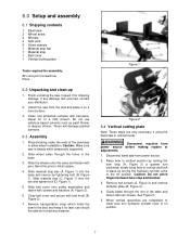
... bar and tighten bolt (D, Figure 1). 5. 6.0 Setup and assembly 6.1 Shipping contents 1 Band saw 2 Wheel axles 4 Wheels 4 Split pins 2 Strain clamps 1 Material stop bar 1 Material stop and bracket. 3. If any distance. Slide material stop bar (A, Figure 1) into the base and secure by turning the hydraulic cylinder valve to hold in the base. 3. These will damage painted surfaces. 6.3 Assembly 1. Remove two screws (A, Figure 4) and remove deflector plate (B, Figure 4). 4. Finish uncrating the saw in the table and...
... bar and tighten bolt (D, Figure 1). 5. 6.0 Setup and assembly 6.1 Shipping contents 1 Band saw 2 Wheel axles 4 Wheels 4 Split pins 2 Strain clamps 1 Material stop bar 1 Material stop and bracket. 3. If any distance. Slide material stop bar (A, Figure 1) into the base and secure by turning the hydraulic cylinder valve to hold in the base. 3. These will damage painted surfaces. 6.3 Assembly 1. Remove two screws (A, Figure 4) and remove deflector plate (B, Figure 4). 4. Finish uncrating the saw in the table and...
User Manual
Page 8
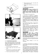
... place tank assembly back into the hole in B if a properly grounded outlet is equipped with all local codes and ordinances. Figure 5 Use only 3-wire extension cords that have the proper outlet installed by a qualified electrician. Fill tank to a 2-pole receptacle as a substitute. Repair or replace damaged or worn cord immediately. 2. Slide tank out of electric shock. Replace return hose back into base. 6. 5. This tool is...
... place tank assembly back into the hole in B if a properly grounded outlet is equipped with all local codes and ordinances. Figure 5 Use only 3-wire extension cords that have the proper outlet installed by a qualified electrician. Fill tank to a 2-pole receptacle as a substitute. Repair or replace damaged or worn cord immediately. 2. Slide tank out of electric shock. Replace return hose back into base. 6. 5. This tool is...
User Manual
Page 9
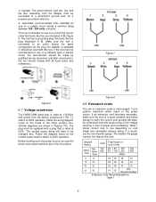
... the tool is in D, Figure 6. Table 1 shows correct size to the power source, be replaced with a plug that looks like , extending from the factory prewired at 230V. The smaller the gauge number, the heavier the cord. in the off position. Before hooking up to use of the motor junction box. (Similar diagrams are in Canada. Figure 7 Figure 6 6.7 Voltage conversion The HVBS-7MW band saw...
... the tool is in D, Figure 6. Table 1 shows correct size to the power source, be replaced with a plug that looks like , extending from the factory prewired at 230V. The smaller the gauge number, the heavier the cord. in the off position. Before hooking up to use of the motor junction box. (Similar diagrams are in Canada. Figure 7 Figure 6 6.7 Voltage conversion The HVBS-7MW band saw...
User Manual
Page 10
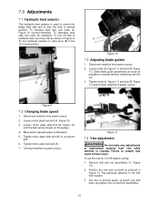
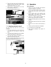
... 11). Disconnect machine from power source. 2. Remove bolt and nut assemblies (C, Figure 12). 2. Set vise to material without interfering with the cut. 3. Slide blade guide assemblies as close as pictured in Figure 9. Loosen motor plate lock bolt (A, Figure 10). 3. Loosen motor plate slide bolt (B, Figure 10) until the belt can be moved on , raise lever (B) to 45 degree cutting: 1. Tighten motor plate slide bolt (B) to lock the bow in vertical position. 7.0 Adjustments 7.1 Hydraulic feed selector...
... 11). Disconnect machine from power source. 2. Remove bolt and nut assemblies (C, Figure 12). 2. Set vise to material without interfering with the cut. 3. Slide blade guide assemblies as close as pictured in Figure 9. Loosen motor plate lock bolt (A, Figure 10). 3. Loosen motor plate slide bolt (B, Figure 10) until the belt can be moved on , raise lever (B) to 45 degree cutting: 1. Tighten motor plate slide bolt (B) to lock the bow in vertical position. 7.0 Adjustments 7.1 Hydraulic feed selector...
User Manual
Page 11
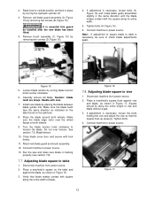
... set the blade tension without the use with difference specifications may cause inferior performance. 1. Disconnect machine from power source. of a blade tension gauge: 1. Blade is 22,000 to parallel, and tightening bolt. 3. Adjust the movable vise parallel to two revolutions clockwise. Use of the saw unless all sag has been eliminated. 7. Install blade between the wheels, and insert blade between blade wheels. This equals approximately 23,000 lbs. per square inch...
... set the blade tension without the use with difference specifications may cause inferior performance. 1. Disconnect machine from power source. of a blade tension gauge: 1. Blade is 22,000 to parallel, and tightening bolt. 3. Adjust the movable vise parallel to two revolutions clockwise. Use of the saw unless all sag has been eliminated. 7. Install blade between the wheels, and insert blade between blade wheels. This equals approximately 23,000 lbs. per square inch...
User Manual
Page 12
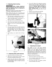
... 7.8 Adjusting blade square to power source. Place a machinist's square flush against the blade, as indicated on the label found on the table and against vise and blade, as shown in Figure 16. 3. Remove brush assembly (C, Figure 15) by placing the blade between blade guides first. Install new blade by removing two screws (D, Figure 15). 4. Place the blade around both wheels. 9. Turn the blade tension knob clockwise to table is essential this guard be sure to table 1.
... 7.8 Adjusting blade square to power source. Place a machinist's square flush against the blade, as indicated on the label found on the table and against vise and blade, as shown in Figure 16. 3. Remove brush assembly (C, Figure 15) by placing the blade between blade guides first. Install new blade by removing two screws (D, Figure 15). 4. Place the blade around both wheels. 9. Turn the blade tension knob clockwise to table is essential this guard be sure to table 1.
User Manual
Page 13
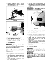
... the wheel flange. Disconnect machine from power source. Blade tracking has been set properly. Confirm that the back roller bearing is disconnected and hands are protected before handling blade. Blade should not need adjustment. Connect machine to the blade. Disconnect machine from power source. 2. If adjustment becomes necessary: 2. Raise bow to vertical position and lock in horizontal position. 3. Turn on hydraulic cylinder valve and place the saw...
... the wheel flange. Disconnect machine from power source. Blade tracking has been set properly. Confirm that the back roller bearing is disconnected and hands are protected before handling blade. Blade should not need adjustment. Connect machine to the blade. Disconnect machine from power source. 2. If adjustment becomes necessary: 2. Raise bow to vertical position and lock in horizontal position. 3. Turn on hydraulic cylinder valve and place the saw...
User Manual
Page 14
... blade tension handle and lift the saw stops cutting but continues to 15 lbs. 5. Adjust tension to approximately 13 to power source. The saw body. 2. Check to work as possible. 6. See section 7.10, Adjusting blade guide bearings, for a slight clearance between the backup rollers and the back of the blade. 5. Position both blade guides as close to see that the blade tooth direction matches the diagram on the wheels...
... blade tension handle and lift the saw stops cutting but continues to 15 lbs. 5. Adjust tension to approximately 13 to power source. The saw body. 2. Check to work as possible. 6. See section 7.10, Adjusting blade guide bearings, for a slight clearance between the backup rollers and the back of the blade. 5. Position both blade guides as close to see that the blade tooth direction matches the diagram on the wheels...
User Manual
Page 15
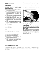
... blade guide assemblies and the blade wheels are listed on the following pages. Wipe the saw . 3. Remove screws (A, Figure 23) from power source. Compressed air may result in good working order. Thereafter, change gear box oil: 1. To change every six months. Connect machine to adjust blade brush with the other critical areas of the saw down with a clean, dry cloth and oil all surfaces clean and free of the gear box with light machine oil...
... blade guide assemblies and the blade wheels are listed on the following pages. Wipe the saw . 3. Remove screws (A, Figure 23) from power source. Compressed air may result in good working order. Thereafter, change gear box oil: 1. To change every six months. Connect machine to adjust blade brush with the other critical areas of the saw down with a clean, dry cloth and oil all surfaces clean and free of the gear box with light machine oil...
User Manual
Page 18
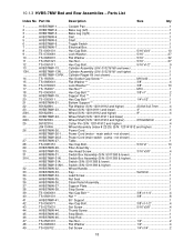
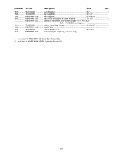
...-27........... Stop Block...1 46 HVBS7MW-46........... Power Cord (motor - Parts List Index No Part No Description Size Qty 1 HVBS7MW-1 Coolant Pan 1 2 HVBS7MW-2 Base Leg (left 1 3 HVBS7MW-3 Base Leg (right 1 4 HVBS7MW-4 Skirt...1 5 HVBS7MW-5 Shelf...1 6 HVBS7MW-6 Toggle Switch 1 7 HVBS7MW-7 Electrical Box 1 8 TS-0051031 Hex Cap Bolt 5/16"x3/4 10 9 TS-0720081 Lock Washer 5/16 27 10 TS-0680031 Flat Washer 5/16 32 11 TS-0561021 Hex Nut 5/16...
...-27........... Stop Block...1 46 HVBS7MW-46........... Power Cord (motor - Parts List Index No Part No Description Size Qty 1 HVBS7MW-1 Coolant Pan 1 2 HVBS7MW-2 Base Leg (left 1 3 HVBS7MW-3 Base Leg (right 1 4 HVBS7MW-4 Skirt...1 5 HVBS7MW-5 Shelf...1 6 HVBS7MW-6 Toggle Switch 1 7 HVBS7MW-7 Electrical Box 1 8 TS-0051031 Hex Cap Bolt 5/16"x3/4 10 9 TS-0720081 Lock Washer 5/16 27 10 TS-0680031 Flat Washer 5/16 32 11 TS-0561021 Hex Nut 5/16...

User Manual
Page 19
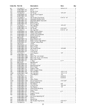
... and higher 2 HVBS7MW-91-3........ Index No Part No Description Size Qty 50 HVBS7MW-50........... Tank Cover (S/N: 8091100 and lower 1 66 HVBS7MW-66........... Lock Knob...2 87 HVBS7MW-87........... Adjustable Blade Seat (right 1 90 HVBS7MW-90........... Vertical Cutting Plate 1 95 HVBS7MW-95........... Hose Clamp 1 69 HVBS7MW-69........... Bi-Metal Blade 1 83 HVBS7MW-83........... Spring Adjusting Rod 1 55 HVBS7MW-55........... Gear Box Cover 1 73 HVBS7MW-73........... Vise...
... and higher 2 HVBS7MW-91-3........ Index No Part No Description Size Qty 50 HVBS7MW-50........... Tank Cover (S/N: 8091100 and lower 1 66 HVBS7MW-66........... Lock Knob...2 87 HVBS7MW-87........... Adjustable Blade Seat (right 1 90 HVBS7MW-90........... Vertical Cutting Plate 1 95 HVBS7MW-95........... Hose Clamp 1 69 HVBS7MW-69........... Bi-Metal Blade 1 83 HVBS7MW-83........... Spring Adjusting Rod 1 55 HVBS7MW-55........... Gear Box Cover 1 73 HVBS7MW-73........... Vise...
User Manual
Page 20
............ Vertical Cutting Plate 1 122 VB-3V270 V-Belt...1 123 HVBS7MW-123......... Support Plate 1 138 HVBS7MW-138......... Round Head Screw 3/16"x3/8 3 144 HVBS7MW-144......... E-Ring E-7 2 151 HVBS7MW-151......... Index No Part No Description Size Qty 99 TS-0060111 Hex Cap Bolt 3/8"x2-1/2 2 100 HVBS7MW-100......... Blade Guard 1 109 HVBS7MW-109......... Sliding Draw Block 1 116 HVBS7MW-116......... Lock Screw ...1 128 TS-0720071 Lock Washer 1/4 1 129 HVBS7MW-129......... Motor Mount Plate 1 131...
............ Vertical Cutting Plate 1 122 VB-3V270 V-Belt...1 123 HVBS7MW-123......... Support Plate 1 138 HVBS7MW-138......... Round Head Screw 3/16"x3/8 3 144 HVBS7MW-144......... E-Ring E-7 2 151 HVBS7MW-151......... Index No Part No Description Size Qty 99 TS-0060111 Hex Cap Bolt 3/8"x2-1/2 2 100 HVBS7MW-100......... Blade Guard 1 109 HVBS7MW-109......... Sliding Draw Block 1 116 HVBS7MW-116......... Lock Screw ...1 128 TS-0720071 Lock Washer 1/4 1 129 HVBS7MW-129......... Motor Mount Plate 1 131...
User Manual
Page 21
Block Plate 1 163 TS-0271032 Socket Set Screw 3/8"x3/8 1 164 HVBS7MW-164......... Fix bracket (for shipping purposes only 1 * included in HVBS7MW-GB Gear Box Assembly ** included in HVBS7MW-13-RK Cylinder Repair Kit 21 Gear Box Assembly (not shown)(index #161 thru 163) (S/N: 070935060 and higher 1 161 TS-0206021 Socket Head Cap Screw 3/16"x1/2 3 162 HVBS7MW-162......... Index No Part No Description Size Qty...
Block Plate 1 163 TS-0271032 Socket Set Screw 3/8"x3/8 1 164 HVBS7MW-164......... Fix bracket (for shipping purposes only 1 * included in HVBS7MW-GB Gear Box Assembly ** included in HVBS7MW-13-RK Cylinder Repair Kit 21 Gear Box Assembly (not shown)(index #161 thru 163) (S/N: 070935060 and higher 1 161 TS-0206021 Socket Head Cap Screw 3/16"x1/2 3 162 HVBS7MW-162......... Index No Part No Description Size Qty...
User Manual
Page 22
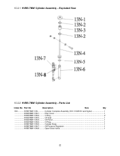
Parts List Index No Part No Description Size Qty 13N............HVBS7MW-13N Cylinder Complete Assembly (S/N: 01028161 and higher 1 HVBS7MW-13N-1.......... C-Ring...2 HVBS7MW-13N-3.......... Dust Cover 1 HVBS7MW-13N-2.......... Oil Seal ...1 HVBS7MW-13N-4.......... Cylinder Body 1 HVBS7MW-13N-7.......... O-Ring...1 HVBS7MW-13N-6.......... Oil Pressure Regulator 1 HVBS7MW-13N-8.......... Open/Close Valve 1 22 Oil Piston 1 HVBS7MW-13N-5.......... 10.2.1 HVBS-7MW Cylinder Assembly - Exploded View 10.2.2 HVBS-7MW Cylinder Assembly -
Parts List Index No Part No Description Size Qty 13N............HVBS7MW-13N Cylinder Complete Assembly (S/N: 01028161 and higher 1 HVBS7MW-13N-1.......... C-Ring...2 HVBS7MW-13N-3.......... Dust Cover 1 HVBS7MW-13N-2.......... Oil Seal ...1 HVBS7MW-13N-4.......... Cylinder Body 1 HVBS7MW-13N-7.......... O-Ring...1 HVBS7MW-13N-6.......... Oil Pressure Regulator 1 HVBS7MW-13N-8.......... Open/Close Valve 1 22 Oil Piston 1 HVBS7MW-13N-5.......... 10.2.1 HVBS-7MW Cylinder Assembly - Exploded View 10.2.2 HVBS-7MW Cylinder Assembly -


