User Manual
Page 3
Exploded View 22 10.2.2 HVBS-7MW Cylinder Assembly - Exploded View 16 10.1.2 HVBS-7MW Bow Assembly - Parts List 18 10.2.1 HVBS-7MW Cylinder Assembly - Parts List 22 11.0 Electrical Connections...23 3 2.0 Table of contents Section Page 1.0 Warranty ... tracking ...13 7.10 Adjusting blade guide bearings 13 7.11 Adjusting bow weight...13 7.12 Adjusting automatic shutoff...14 8.0 Operation ...14 9.0 Maintenance...15 9.1 Lubrication ...15 9.2 Chip Cleaning Brush ...15 10.0 Replacement Parts...15 10.1.1 HVBS-7MW Bed Assembly - Exploded View 17 10.1.3 HVBS-7MW Bed and...
Exploded View 22 10.2.2 HVBS-7MW Cylinder Assembly - Exploded View 16 10.1.2 HVBS-7MW Bow Assembly - Parts List 18 10.2.1 HVBS-7MW Cylinder Assembly - Parts List 22 11.0 Electrical Connections...23 3 2.0 Table of contents Section Page 1.0 Warranty ... tracking ...13 7.10 Adjusting blade guide bearings 13 7.11 Adjusting bow weight...13 7.12 Adjusting automatic shutoff...14 8.0 Operation ...14 9.0 Maintenance...15 9.1 Lubrication ...15 9.2 Chip Cleaning Brush ...15 10.0 Replacement Parts...15 10.1.1 HVBS-7MW Bed Assembly - Exploded View 17 10.1.3 HVBS-7MW Bed and...
User Manual
Page 4
...or operation. 2. A guard or other part that are careless acts that use this table saw , remove tie, rings, watches and other purposes, JET disclaims any real or implied warranty and holds itself harmless from any machine operation. 4 Provide for other jewelry, and roll sleeves up past the ... the influence of checking to perform any injury that may result from blade at all times when the machine is properly grounded. 13. Wear ear protectors (plugs or muffs) during operation. 18. Do not operate this band saw . Maintain a balanced stance at all of...
...or operation. 2. A guard or other part that are careless acts that use this table saw , remove tie, rings, watches and other purposes, JET disclaims any real or implied warranty and holds itself harmless from any machine operation. 4 Provide for other jewelry, and roll sleeves up past the ... the influence of checking to perform any injury that may result from blade at all times when the machine is properly grounded. 13. Wear ear protectors (plugs or muffs) during operation. 18. Do not operate this band saw . Maintain a balanced stance at all of...
User Manual
Page 10
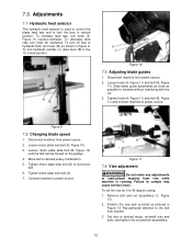
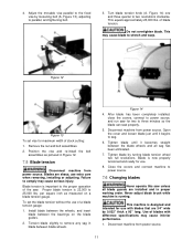
... 12). 2. 7.0 Adjustments 7.1 Hydraulic feed selector The hydraulic feed selector is running. To decrease feed rate, turn lever (B) as possible to lock the bow in Figure 13. To set the vise for 0 to power source. Position the vise and re-install as pictured in vertical position.
... 12). 2. 7.0 Adjustments 7.1 Hydraulic feed selector The hydraulic feed selector is running. To decrease feed rate, turn lever (B) as possible to lock the bow in Figure 13. To set the vise for 0 to power source. Position the vise and re-install as pictured in vertical position.
User Manual
Page 11
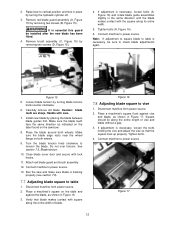
...is 22,000 to sag. 6. Disconnect machine from power source. Adjust the movable vise parallel to the fixed vise by loosening bolt (A, Figure 13), adjusting to two revolutions clockwise. Blades are installed and in proper working order. Figure 14 4. Blade is designed and intended for use with difference... it begins to 25,000 lbs. Tighten blade by 0.032" thick x 93" long. This equals approximately 23,000 lbs. Figure 12 Figure 13 To set the blade tension without the use extra care when removing, installing or adjusting. Failure to remove any sag in Figure 12. 7.5 Blade...
...is 22,000 to sag. 6. Disconnect machine from power source. Adjust the movable vise parallel to the fixed vise by loosening bolt (A, Figure 13), adjusting to two revolutions clockwise. Blades are installed and in proper working order. Figure 14 4. Blade is designed and intended for use with difference... it begins to 25,000 lbs. Tighten blade by 0.032" thick x 93" long. This equals approximately 23,000 lbs. Figure 12 Figure 13 To set the blade tension without the use extra care when removing, installing or adjusting. Failure to remove any sag in Figure 12. 7.5 Blade...
User Manual
Page 12
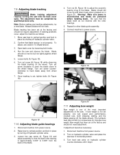
... screws (D, Figure 15). 4. Caution: blade teeth are sharp. Connect machine to vise 1. Disconnect machine from power source. 2. Figure 16 7.8 Adjusting blade square to power source. 13. If adjustment is necessary, be installed after the new blade has been fitted. 4. Tighten bolts. 4. Figure 15 5. See section 7.5, Blade tension. 10. Place the blade...
... screws (D, Figure 15). 4. Caution: blade teeth are sharp. Connect machine to vise 1. Disconnect machine from power source. 2. Figure 16 7.8 Adjusting blade square to power source. 13. If adjustment is necessary, be installed after the new blade has been fitted. 4. Tighten bolts. 4. Figure 15 5. See section 7.5, Blade tension. 10. Place the blade...
User Manual
Page 13
... assembly so that the back roller bearing is set screw (B, Figure 18) while observing the blade tracking on hydraulic cylinder counter-clockwise until it stops. 13 Turn feed rate valve on the wheel. Move saw bow in place by turning off the blade wheels. Warning! This adjustment must be completed by...
... assembly so that the back roller bearing is set screw (B, Figure 18) while observing the blade tracking on hydraulic cylinder counter-clockwise until it stops. 13 Turn feed rate valve on the wheel. Move saw bow in place by turning off the blade wheels. Warning! This adjustment must be completed by...
User Manual
Page 14
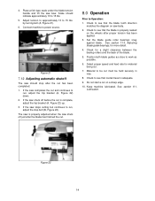
Figure 21 7.12 Adjusting automatic shutoff The saw should indicate approximately 13 to see that coolant level is complete, adjust the trip bracket (A, Figure 22) up. 3. Check to 15 lbs. 5. Check for material being cut. 7. Material to ... machine lubricated. See section 7.10, Adjusting blade guide bearings, for more detail. 4. Set the blade guide roller bearings snug against blade. Adjust tension to approximately 13 to see that the blade tooth direction matches the diagram on saw stops cutting but continues to be held securely in vise. 8. The saw is...
Figure 21 7.12 Adjusting automatic shutoff The saw should indicate approximately 13 to see that coolant level is complete, adjust the trip bracket (A, Figure 22) up. 3. Check to 15 lbs. 5. Check for material being cut. 7. Material to ... machine lubricated. See section 7.10, Adjusting blade guide bearings, for more detail. 4. Set the blade guide roller bearings snug against blade. Adjust tension to approximately 13 to see that the blade tooth direction matches the diagram on saw stops cutting but continues to be held securely in vise. 8. The saw is...
User Manual
Page 18
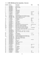
... Flat Washer 5/16 32 11 TS-0561021 Hex Nut 5/16 27 12 TS-0051011 Hex Cap Bolt 5/16"x1/2 9 13 HVBS7MW-13........... Cylinder Repair Kit (not shown 1 14 TS-150506 Hex Socket Cap Screw M10x40 1 15 TS-0680041 Flat Washer 3/8 ... Hex Cap Bolt 1/4"x1/2 1 21 HVBS7MW-21........... Switch (S/N: 5011368 & lower 1 HVBS7MW-31AN...... Wheel Handle 1 33 HVBS7MW-33........... 10.1.3 HVBS-7MW Bed and Bow Assemblies - Cylinder Assembly (S/N: 010218160 and lower 1 13N............HVBS7MW-13N ........ Bottom Support 1 22 5518228N Flat Washer (S/N: 120141912 and higher...
... Flat Washer 5/16 32 11 TS-0561021 Hex Nut 5/16 27 12 TS-0051011 Hex Cap Bolt 5/16"x1/2 9 13 HVBS7MW-13........... Cylinder Repair Kit (not shown 1 14 TS-150506 Hex Socket Cap Screw M10x40 1 15 TS-0680041 Flat Washer 3/8 ... Hex Cap Bolt 1/4"x1/2 1 21 HVBS7MW-21........... Switch (S/N: 5011368 & lower 1 HVBS7MW-31AN...... Wheel Handle 1 33 HVBS7MW-33........... 10.1.3 HVBS-7MW Bed and Bow Assemblies - Cylinder Assembly (S/N: 010218160 and lower 1 13N............HVBS7MW-13N ........ Bottom Support 1 22 5518228N Flat Washer (S/N: 120141912 and higher...
User Manual
Page 21
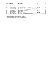
... TS-0271032 Socket Set Screw 3/8"x3/8 1 164 HVBS7MW-164......... Fix bracket (for shipping purposes only 1 * included in HVBS7MW-GB Gear Box Assembly ** included in HVBS7MW-13-RK Cylinder Repair Kit 21 Hex Cap Bolt 5/16"x3/4 1 160 HVBS7MW-160......... Hex Cross Head Bolt w/ Lock Washer 1/4"x1/2 4 HVBS7MW-GB.......... Gear Box Assembly...
... TS-0271032 Socket Set Screw 3/8"x3/8 1 164 HVBS7MW-164......... Fix bracket (for shipping purposes only 1 * included in HVBS7MW-GB Gear Box Assembly ** included in HVBS7MW-13-RK Cylinder Repair Kit 21 Hex Cap Bolt 5/16"x3/4 1 160 HVBS7MW-160......... Hex Cross Head Bolt w/ Lock Washer 1/4"x1/2 4 HVBS7MW-GB.......... Gear Box Assembly...