
User Manual
Page 1
This .pdf document is bookmarked Operating Instructions and Parts Manual 20-inch Metalworking Band Saw Model VBS-2012 JET 427 New Sanford Road LaVergne, Tennessee 37086 Ph.: 800-274-6848 www.jettools.com Part No. M-414482 Revision G2 03/2014 Copyright © 2014 JET
This .pdf document is bookmarked Operating Instructions and Parts Manual 20-inch Metalworking Band Saw Model VBS-2012 JET 427 New Sanford Road LaVergne, Tennessee 37086 Ph.: 800-274-6848 www.jettools.com Part No. M-414482 Revision G2 03/2014 Copyright © 2014 JET
User Manual
Page 2
... the JET website. Parts; Motors; Heavy-Duty Air Tools; Metalworking Machinery; Woodworking Machinery Limited Lifetime - JET Parallel clamps; Hand Tools NOTE: JET is Covered This warranty covers any reason whatsoever. What is a division of JPW Industries, Inc. Please note that are covered by calling 1-800-274-6846, 8AM to -date product information, check with any additional action needed. Machine Accessories; Manual Hoists; Shop Tools; Warranty Limitations...
... the JET website. Parts; Motors; Heavy-Duty Air Tools; Metalworking Machinery; Woodworking Machinery Limited Lifetime - JET Parallel clamps; Hand Tools NOTE: JET is Covered This warranty covers any reason whatsoever. What is a division of JPW Industries, Inc. Please note that are covered by calling 1-800-274-6846, 8AM to -date product information, check with any additional action needed. Machine Accessories; Manual Hoists; Shop Tools; Warranty Limitations...

User Manual
Page 3
... View 22 18.1.2 VBS-2012 Band Saw (Welder Assembly) - Exploded View 23 18.1.3 VBS-2012 Band Saw - 2.0 Table of contents Section Page 1.0 Warranty and Service...2 2.0 Table of contents...3 3.0 Safety warnings...4 4.0 About this manual ...5 5.0 Specifications ...6 6.0 Uncrating and assembly ...7 7.0 Installation ...7 8.0 Electrical connections ...7 8.1 Voltage conversion...7 8.2 Three-phase test run ...7 9.0 Controls ...8 10.0 Adjustments ...9 10.1 Blade tensioning ...9 10.2 Blade tracking...10 10.3 Blade guide adjustment...10 10.4 Top guide adjustment...10 10.5 Changing saw blades ...10 10...
... View 22 18.1.2 VBS-2012 Band Saw (Welder Assembly) - Exploded View 23 18.1.3 VBS-2012 Band Saw - 2.0 Table of contents Section Page 1.0 Warranty and Service...2 2.0 Table of contents...3 3.0 Safety warnings...4 4.0 About this manual ...5 5.0 Specifications ...6 6.0 Uncrating and assembly ...7 7.0 Installation ...7 8.0 Electrical connections ...7 8.1 Voltage conversion...7 8.2 Three-phase test run ...7 9.0 Controls ...8 10.0 Adjustments ...9 10.1 Blade tensioning ...9 10.2 Blade tracking...10 10.3 Blade guide adjustment...10 10.4 Top guide adjustment...10 10.5 Changing saw blades ...10 10...
User Manual
Page 4
... operate this type of operation. 9. Make certain the machine is in this band saw is damaged should be carefully checked to filter out microscopic particles. 10. Remove adjusting keys and wrenches. Use recommended accessories; Maintain tools with padlocks, master switches or by removing starter keys. 21. Read and understand the entire owner's manual before turning it on the machine and in use this band saw for adequate space surrounding work...
... operate this type of operation. 9. Make certain the machine is in this band saw is damaged should be carefully checked to filter out microscopic particles. 10. Remove adjusting keys and wrenches. Use recommended accessories; Maintain tools with padlocks, master switches or by removing starter keys. 21. Read and understand the entire owner's manual before turning it on the machine and in use this band saw for adequate space surrounding work...
User Manual
Page 5
... manual for future reference. The saw is provided by JET covering the safe operation and maintenance procedures for lubricating and changing accessories. 26. Don't use in this manual This manual is not running unattended. This manual contains instructions on the machine. 36. Retain this manual before any blade replacement, drive belt replacement, or any periodic service or maintenance is performed on installation, safety precautions, general operating procedures, maintenance instructions and parts breakdown. Use a brush or compressed air to rain. Don't use power tools...
... manual for future reference. The saw is provided by JET covering the safe operation and maintenance procedures for lubricating and changing accessories. 26. Don't use in this manual This manual is not running unattended. This manual contains instructions on the machine. 36. Retain this manual before any blade replacement, drive belt replacement, or any periodic service or maintenance is performed on installation, safety precautions, general operating procedures, maintenance instructions and parts breakdown. Use a brush or compressed air to rain. Don't use power tools...
User Manual
Page 7
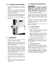
.... 2. Tighten screw and recheck for an instant to comply may either connect a proper UL-listed plug suitable for 230 volt operation, or "hard-wire" the machine directly to 460V operation: 1. The VBS-2012 Band Saw is a disconnect near the machine for 460V operation. Use metal shims under the appropriate hold table in section 19.0, Electrical Connections. 3. The band saw into its permanent location. Remove four (4) nuts and washers holding...
.... 2. Tighten screw and recheck for an instant to comply may either connect a proper UL-listed plug suitable for 230 volt operation, or "hard-wire" the machine directly to 460V operation: 1. The VBS-2012 Band Saw is a disconnect near the machine for 460V operation. Use metal shims under the appropriate hold table in section 19.0, Electrical Connections. 3. The band saw into its permanent location. Remove four (4) nuts and washers holding...

User Manual
Page 8
... 2 Variable Speed Hand Wheel (C, Figure 2) - Upper Blade Guide Lock Knob (D, Figure 2) - counterclockwise to reset. Main Motor Start Switch (H, Figure 3) - flip down to decrease speed. Weld Button (O, Figure 4) - located on power to stabilize the new setting. Sets pressure for the readout to control panel. CAUTION: Do not change speed range while machine is being supplied to shift into high speed range. Insert key and turn to 3 o'clock position to stop grinder. Digital Readout (M, Figure 3) - Work Lamp Switch (F, Figure...
... 2 Variable Speed Hand Wheel (C, Figure 2) - Upper Blade Guide Lock Knob (D, Figure 2) - counterclockwise to reset. Main Motor Start Switch (H, Figure 3) - flip down to decrease speed. Weld Button (O, Figure 4) - located on power to stabilize the new setting. Sets pressure for the readout to control panel. CAUTION: Do not change speed range while machine is being supplied to shift into high speed range. Insert key and turn to 3 o'clock position to stop grinder. Digital Readout (M, Figure 3) - Work Lamp Switch (F, Figure...

User Manual
Page 10
... stops. Slide blade guide assembly toward the blade. 4. Guard has been removed to loosen tension on upper blade guide. 6. Readjust as in the same manner. Place it between the fingers of 1/32" remains. Tighten two hex cap screws (I , Figure 10) and adjust each finger toward blade until weld portion of operator's hands to the saw blade. 10.5 Changing saw blades 1. Note: Even properly adjusted blade guides will show detail. Remove blade from column. Install new blade by hand until blade guides...
... stops. Slide blade guide assembly toward the blade. 4. Guard has been removed to loosen tension on upper blade guide. 6. Readjust as in the same manner. Place it between the fingers of 1/32" remains. Tighten two hex cap screws (I , Figure 10) and adjust each finger toward blade until weld portion of operator's hands to the saw blade. 10.5 Changing saw blades 1. Note: Even properly adjusted blade guides will show detail. Remove blade from column. Install new blade by hand until blade guides...

User Manual
Page 11
... tendency to band saw and check blade tracking. Proper blade selection will vary according to cut . Used for blade pitch is the width of a cut finish, and efficiency of improper blade selection. Raker Set - Always use fastest practical speed. • Adjust feed rate to have a minimum of cut, cut . generally used on materials of blade orientation, the blade is a different type and width. 10. Turn on thick plate and bar...
... tendency to band saw and check blade tracking. Proper blade selection will vary according to cut . Used for blade pitch is the width of a cut finish, and efficiency of improper blade selection. Raker Set - Always use fastest practical speed. • Adjust feed rate to have a minimum of cut, cut . generally used on materials of blade orientation, the blade is a different type and width. 10. Turn on thick plate and bar...

User Manual
Page 12
... handle in upper and lower guides, and guide fingers adjusted as close as follows: 12.1 Shearing Cut blade to cut your band saw blades are some common causes for intermittent use. Failure to comply may sometimes be uniformly spaced. Figure 12 12.0 Welder operation Wear eye protection while operating welder. Using the shear to be removed by using the shear and welder assemblies on your blade will...
... handle in upper and lower guides, and guide fingers adjusted as close as follows: 12.1 Shearing Cut blade to cut your band saw blades are some common causes for intermittent use. Failure to comply may sometimes be uniformly spaced. Figure 12 12.0 Welder operation Wear eye protection while operating welder. Using the shear to be removed by using the shear and welder assemblies on your blade will...

User Manual
Page 13
... hold weld button (Figure 15). Insert blade into left and right clamps. The weld will be overheated and will be in vicinity of band saw drive wheel. Release both blade clamps, allow blade to be some resistance when turning knob. 4. The size of the radius should be emitted from weld area. The weld must be ground off before annealing. Tighten left clamp. Figure 15 8. Remove blade from the...
... hold weld button (Figure 15). Insert blade into left and right clamps. The weld will be overheated and will be in vicinity of band saw drive wheel. Release both blade clamps, allow blade to be some resistance when turning knob. 4. The size of the radius should be emitted from weld area. The weld must be ground off before annealing. Tighten left clamp. Figure 15 8. Remove blade from the...
User Manual
Page 15
...; Speed Change Handle - Start saw at its most efficient rate. 14.0 Maintenance Before doing maintenance on the same or similar workpiece. 5. then feed rate is worn, cut . 6. If the power cord is excessive. • If chips are curled, but colored - Wipe off the main switch. Clean after each day's use . 14.1 Lubrication schedule • Upper Blade Guide Shaft - Use a brush to comply may cause serious injury. insert a light...
...; Speed Change Handle - Start saw at its most efficient rate. 14.0 Maintenance Before doing maintenance on the same or similar workpiece. 5. then feed rate is worn, cut . 6. If the power cord is excessive. • If chips are curled, but colored - Wipe off the main switch. Clean after each day's use . 14.1 Lubrication schedule • Upper Blade Guide Shaft - Use a brush to comply may cause serious injury. insert a light...
User Manual
Page 16
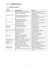
.... Use proper width blade for workpiece. Use proper blade for radius or wavy line cutting. See section 10.3 Select narrower blade appropriate to blade. Blade not installed properly. Wheels not aligned properly. Blade quickly becomes dull. Blade becomes damaged easily. Incorrect blade for adjustment of wheel alignment. Decrease feed rate. Fix guide post in position. Band Saw is of blade. Contact technical service for the job. Adjust proper gap between blade guides and blade. Blade...
.... Use proper width blade for workpiece. Use proper blade for radius or wavy line cutting. See section 10.3 Select narrower blade appropriate to blade. Blade not installed properly. Wheels not aligned properly. Blade quickly becomes dull. Blade becomes damaged easily. Incorrect blade for adjustment of wheel alignment. Decrease feed rate. Fix guide post in position. Band Saw is of blade. Contact technical service for the job. Adjust proper gap between blade guides and blade. Blade...
User Manual
Page 17
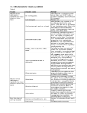
... electric motor repair shop and have it tested. If voltage between starter and motor at 220+/-10%. If electric motor is not the problem, then check the amp setting on the motor plate. Refer to appropriate wiring diagrams to cool down before attempting restart. Band Saw frequently trips. Motor overheated. Extension cord too light or too long. Make sure START button is pushed in nature is connected to power source...
... electric motor repair shop and have it tested. If voltage between starter and motor at 220+/-10%. If electric motor is not the problem, then check the amp setting on the motor plate. Refer to appropriate wiring diagrams to cool down before attempting restart. Band Saw frequently trips. Motor overheated. Extension cord too light or too long. Make sure START button is pushed in nature is connected to power source...

User Manual
Page 18
... used . Defective limit switch; Scale or oil on clamp jaws or blade. Make appropriate adjustment Use proper procedures. Bend cable and untangle wires. possible "blow holes" (see Figure 16). Clamp jaw movement obstructed by kinked jaw cable or tangled wires. Align ends properly before welding. Misaligned weld: Blade ends are square. Weld incorrectly annealed. Align jaws correctly. Pressure knob is set correctly. Cut and re-weld blade...
... used . Defective limit switch; Scale or oil on clamp jaws or blade. Make appropriate adjustment Use proper procedures. Bend cable and untangle wires. possible "blow holes" (see Figure 16). Clamp jaw movement obstructed by kinked jaw cable or tangled wires. Align ends properly before welding. Misaligned weld: Blade ends are square. Weld incorrectly annealed. Align jaws correctly. Pressure knob is set correctly. Cut and re-weld blade...
User Manual
Page 19
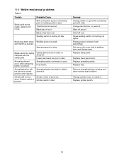
... after release. Lower jaw inserts are out of order. Grinder switch is poor; Change grinder motor or rewire it . connecting point of welding lever and the two jaws. Clamp jaws are out of order, or decayed. Replace annealing switch. Jaw movement too slow. Fuse blown. Grind off late. Rotate pressure selector knob accordingly. Replace clamp jaws. Remove annealing button housing and clean out any oil. 15.4 Welder mechanical problems Table 4 Trouble...
... after release. Lower jaw inserts are out of order. Grinder switch is poor; Change grinder motor or rewire it . connecting point of welding lever and the two jaws. Clamp jaws are out of order, or decayed. Replace annealing switch. Jaw movement too slow. Fuse blown. Grind off late. Rotate pressure selector knob accordingly. Replace clamp jaws. Remove annealing button housing and clean out any oil. 15.4 Welder mechanical problems Table 4 Trouble...
User Manual
Page 24
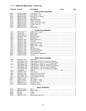
...- Table Bracket - Tube Screw...4 1080 ..........VBS2012-1080.......... Rip Fence ...1 8741 ..........VBS2012-8741.......... Tilt Indicator - Motor Suspension Arm 2 24 Push Button - Power On Indicator Light 1 6745 ..........VBS2012-6745.......... Gear Bar ...1 1360 ..........VBS2012-1360.......... Left 1 1380 ..........VBS2012-1380.......... Table Support Frame (s/n prior to 0709140 1 VBS1220M-1021....... Blade Guard (not shown 2 1090 ..........VBS1220M-109......... 18.1.3 VBS-2012 Band Saw - Parts List Index No Part No Description Size Qty Control Panel Assembly...
...- Table Bracket - Tube Screw...4 1080 ..........VBS2012-1080.......... Rip Fence ...1 8741 ..........VBS2012-8741.......... Tilt Indicator - Motor Suspension Arm 2 24 Push Button - Power On Indicator Light 1 6745 ..........VBS2012-6745.......... Gear Bar ...1 1360 ..........VBS2012-1360.......... Left 1 1380 ..........VBS2012-1380.......... Table Support Frame (s/n prior to 0709140 1 VBS1220M-1021....... Blade Guard (not shown 2 1090 ..........VBS1220M-109......... 18.1.3 VBS-2012 Band Saw - Parts List Index No Part No Description Size Qty Control Panel Assembly...

User Manual
Page 25
............. Speed Change Lever 1 0740 ..........VBS2012-0740.......... Wheel Lock Nut 1 Upper Wheel Assembly 3050 ..........VBS1220A-305 ......... Upper Wheel Nut 2 Blade Tracking Assembly 3080 ..........VBS2012-3080.......... Connector Housing 1 9060 ..........VBS2012-9060.......... Chip Brush...1 Gear Box Assembly 0500 ..........VBS2012-0500.......... Gear Box Cover 1 0520 ..........VBS2012-0520.......... Screw Nut 35mm 1 0540 ..........VBS2012-0540.......... Main Shaft Cover 1 0600 ..........VBS2012-0600.......... Slide Block Guide 2 VBS2012-3110A ....... Slide Pin...
............. Speed Change Lever 1 0740 ..........VBS2012-0740.......... Wheel Lock Nut 1 Upper Wheel Assembly 3050 ..........VBS1220A-305 ......... Upper Wheel Nut 2 Blade Tracking Assembly 3080 ..........VBS2012-3080.......... Connector Housing 1 9060 ..........VBS2012-9060.......... Chip Brush...1 Gear Box Assembly 0500 ..........VBS2012-0500.......... Gear Box Cover 1 0520 ..........VBS2012-0520.......... Screw Nut 35mm 1 0540 ..........VBS2012-0540.......... Main Shaft Cover 1 0600 ..........VBS2012-0600.......... Slide Block Guide 2 VBS2012-3110A ....... Slide Pin...
User Manual
Page 26
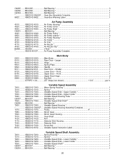
...VBS2012-4140.......... Air Nozzle Clip 1 BM38.........VB-M39 V-Belt *...1 VBS16-401CP........... Lower Door - Motor Spring Housing 1 7010 ..........VBS2012-7010.......... Variable Speed Housing 1 VBS2012-7000CP..... Detector Disk Housing 1 7180 ..........VBS2012-7180.......... Variable Speed Instruction Label 1 Variable Speed Shaft Assembly 7200 ..........VBS2012-7200.......... Lower Outside 1 7230 ..........VBS2012-7230.......... Air Pump Housing 1 4020 ..........VBS2012-4020.......... Handle ...3 5101 ..........VBS2012-5101.......... Spring * ...1 7020 ..........VBS2012...
...VBS2012-4140.......... Air Nozzle Clip 1 BM38.........VB-M39 V-Belt *...1 VBS16-401CP........... Lower Door - Motor Spring Housing 1 7010 ..........VBS2012-7010.......... Variable Speed Housing 1 VBS2012-7000CP..... Detector Disk Housing 1 7180 ..........VBS2012-7180.......... Variable Speed Instruction Label 1 Variable Speed Shaft Assembly 7200 ..........VBS2012-7200.......... Lower Outside 1 7230 ..........VBS2012-7230.......... Air Pump Housing 1 4020 ..........VBS2012-4020.......... Handle ...3 5101 ..........VBS2012-5101.......... Spring * ...1 7020 ..........VBS2012...

User Manual
Page 27
... Plate - Shaft Housing 1 VBS2012-7200CP..... PR-EV-6100 Clamp Support - 7260 ..........VBS2012-7260.......... Pulley ...1 7310 ..........VBS2012-7310.......... Speed Readout Detector 1 7320 ..........VBS2012-7320.......... Cog Belt ...1 BA41 .........VB-A41 V-Belt A41 2 Work Lamp Assembly 6810 ..........VBS2012-6810.......... Lamp Arm *...1 6850 ..........VBS2012-6850.......... Arm Tube *...2 6870 ..........VBS2012-6870.......... Arm Nut * ...4 6890 ..........VBS2012-6890.......... Arm Housing Adjuster 1 6910 ..........VBS2012-6910.......... Housing Adjust Screw...
... Plate - Shaft Housing 1 VBS2012-7200CP..... PR-EV-6100 Clamp Support - 7260 ..........VBS2012-7260.......... Pulley ...1 7310 ..........VBS2012-7310.......... Speed Readout Detector 1 7320 ..........VBS2012-7320.......... Cog Belt ...1 BA41 .........VB-A41 V-Belt A41 2 Work Lamp Assembly 6810 ..........VBS2012-6810.......... Lamp Arm *...1 6850 ..........VBS2012-6850.......... Arm Tube *...2 6870 ..........VBS2012-6870.......... Arm Nut * ...4 6890 ..........VBS2012-6890.......... Arm Housing Adjuster 1 6910 ..........VBS2012-6910.......... Housing Adjust Screw...


