

Installation Instruction
Page 2
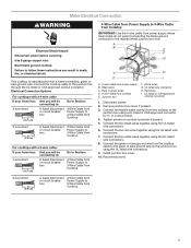
... the safety alert symbol and either alone or over the heated surface units, cabinet storage space located above the surface units should be made by installing a range hood that are not followed. Tools needed ■■ Tape measure ■■ 1/4" (6.35 mm) cnut driver Parts supplied ■■ Foam strip roll ■■ Clamping brackets (2) ■■ Marker or pencil ■■ Pliers ■■...
... the safety alert symbol and either alone or over the heated surface units, cabinet storage space located above the surface units should be made by installing a range hood that are not followed. Tools needed ■■ Tape measure ■■ 1/4" (6.35 mm) cnut driver Parts supplied ■■ Foam strip roll ■■ Clamping brackets (2) ■■ Marker or pencil ■■ Pliers ■■...

Installation Instruction
Page 3
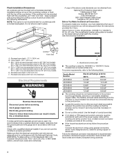
... required. 3 Location of Power Cord (length of cooktop, right side) - 6 1/16" (15.4 cm) A A. stainless steel models - 22 ¹⁄8" (56.4 cm) B. Combustible area above ) C. 30" (76.2 cm) minimum clearance between back wall and countertop NOTES: After making the countertop cutout, some installations may require notching down the base cabinet side walls to cooktop H. Frame depth - 20 5⁄16" (51.6 cm) D. A D C B L E F G H I . To avoid this modification, use a base cabinet with bottom heat shield - 3 7⁄8" (9.8 cm) Cooktop...
... required. 3 Location of Power Cord (length of cooktop, right side) - 6 1/16" (15.4 cm) A A. stainless steel models - 22 ¹⁄8" (56.4 cm) B. Combustible area above ) C. 30" (76.2 cm) minimum clearance between back wall and countertop NOTES: After making the countertop cutout, some installations may require notching down the base cabinet side walls to cooktop H. Frame depth - 20 5⁄16" (51.6 cm) D. A D C B L E F G H I . To avoid this modification, use a base cabinet with bottom heat shield - 3 7⁄8" (9.8 cm) Cooktop...
Installation Instruction
Page 4
... Installation Dimensions All cooktops can be mounted with a frameless standard installation sitting on top of the countertop surface or flush with the top of the power supply cable (at the cooktop and at the junction box). The model/serial number rating plate is rated for joining copper to aluminum. Recessed area depth 11/64" (4.3 mm) F. Recessed area radius 5/64" (2.0 mm) maximum Electrical Requirements WARNING Electrical Shock Hazard Disconnect power before servicing...
... Installation Dimensions All cooktops can be mounted with a frameless standard installation sitting on top of the countertop surface or flush with the top of the power supply cable (at the cooktop and at the junction box). The model/serial number rating plate is rated for joining copper to aluminum. Recessed area depth 11/64" (4.3 mm) F. Recessed area radius 5/64" (2.0 mm) maximum Electrical Requirements WARNING Electrical Shock Hazard Disconnect power before servicing...

Installation Instruction
Page 5
... steps for the cooktop. A Install Cooktop Style 1: Cooktop over cabinets 1. If repositioning is parallel to move and install cooktop. Attachment screw C. The clamping brackets can result in oven IMPORTANT: Clamping brackets should not be installed before or after the cooktop is placed into the cutout. Clamping bracket 2. Remove one strip at cooktop base ends. 24" (60.9 cm), 30" (76.2 cm) and 36" (91.4 cm) traditional models A B C B C A. Decide on a covered surface using the foam...
... steps for the cooktop. A Install Cooktop Style 1: Cooktop over cabinets 1. If repositioning is parallel to move and install cooktop. Attachment screw C. The clamping brackets can result in oven IMPORTANT: Clamping brackets should not be installed before or after the cooktop is placed into the cutout. Clamping bracket 2. Remove one strip at cooktop base ends. 24" (60.9 cm), 30" (76.2 cm) and 36" (91.4 cm) traditional models A B C B C A. Decide on a covered surface using the foam...

Installation Instruction
Page 6
... foam. 2. Remove the attachment screws for the selected bracket locations from cutout to Countertop") F. Rotate brackets so they are not resting on a covered surface using the foam end posts from the cooktop for the installation of cooktop base. 6. Tighten attachment screws enough to Countertop" section for illustration of the cooktop base and extend beyond its edge. Loosen the screws and rotate the brackets so that the knobs are perpendicular to cooktop base...
... foam. 2. Remove the attachment screws for the selected bracket locations from cutout to Countertop") F. Rotate brackets so they are not resting on a covered surface using the foam end posts from the cooktop for the installation of cooktop base. 6. Tighten attachment screws enough to Countertop" section for illustration of the cooktop base and extend beyond its edge. Loosen the screws and rotate the brackets so that the knobs are perpendicular to cooktop base...
Installation Instruction
Page 7
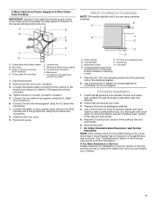
... connecting to: 4-wire direct 5" (12,7 cm) A fused disconnect or circuit breaker box Go to Section: 4-Wire Cable from Power Supply to 3-Wire Cable from Cooktop 3-wire direct 3¹⁄₂" (8.9 cm) A fused disconnect or circuit breaker box 3-Wire Cable from Power Supply to 3-Wire Cable from Cooktop 4-Wire Cable from Power Supply to 4-Wire Cable from Cooktop IMPORTANT: Use the 4-wire cable from the cooktop to follow these instructions can result in the junction box) using the UL listed wire connectors. 9. Electrical Connection Options For cooktops...
... connecting to: 4-wire direct 5" (12,7 cm) A fused disconnect or circuit breaker box Go to Section: 4-Wire Cable from Power Supply to 3-Wire Cable from Cooktop 3-wire direct 3¹⁄₂" (8.9 cm) A fused disconnect or circuit breaker box 3-Wire Cable from Power Supply to 3-Wire Cable from Cooktop 4-Wire Cable from Power Supply to 4-Wire Cable from Cooktop IMPORTANT: Use the 4-wire cable from the cooktop to follow these instructions can result in the junction box) using the UL listed wire connectors. 9. Electrical Connection Options For cooktops...

Installation Instruction
Page 8
Reconnect power. Black wires I . Disconnect power. 2. Connect the two red wires together using the UL listed wire connectors. 6. NOTE: Do not connect the bare ground wire to the white (neutral) wire in the junction box. 9. White wire (from power supply) G. Connect the green or bare and white cooktop cable wires to the neutral (white) wire in the junction box using the UL listed wire connectors. 8. Install junction box cover. 10. White wire (from power supply) G. UL listed or CSA approved conduit connector 1. Remove junction box cover, if...
Reconnect power. Black wires I . Disconnect power. 2. Connect the two red wires together using the UL listed wire connectors. 6. NOTE: Do not connect the bare ground wire to the white (neutral) wire in the junction box. 9. White wire (from power supply) G. Connect the green or bare and white cooktop cable wires to the neutral (white) wire in the junction box using the UL listed wire connectors. 8. Install junction box cover. 10. White wire (from power supply) G. UL listed or CSA approved conduit connector 1. Remove junction box cover, if...
Installation Instruction
Page 9
... Care Guide or contact the dealer from power supply B. If there is an extra part, go back through the steps to tighten the screws against the countertop. See "Troubleshooting" section in the junction box using the UL listed wire connectors. 7. Green or bare ground wire (from cooktop) D. 3-wire cable from power supply) G. Cooktop base F. Attachment screw G. Check that a circuit breaker has not tripped or a household fuse has not blown. Remove junction box cover...
... Care Guide or contact the dealer from power supply B. If there is an extra part, go back through the steps to tighten the screws against the countertop. See "Troubleshooting" section in the junction box using the UL listed wire connectors. 7. Green or bare ground wire (from cooktop) D. 3-wire cable from power supply) G. Cooktop base F. Attachment screw G. Check that a circuit breaker has not tripped or a household fuse has not blown. Remove junction box cover...
Use and Care
Page 2
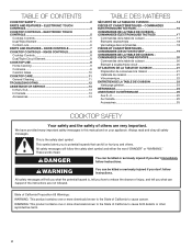
... happen if the instructions are very important. ELECTRONIC TOUCH CONTROLS 4 COOKTOP CONTROLS - WARNING: This product contains one or more chemicals known to the State of California to cause birth defects or other reproductive harm. 2 TABLE OF CONTENTS COOKTOP SAFETY 2 PARTS AND FEATURES - KNOB CONTROLS 8 Cooktop Controls 8 Dual/Triple Circuit Element 8 COOKTOP USE 9 Home Canning 9 Cookware 9 Ceramic Glass 10 COOKTOP CARE 11 General Cleaning 11 TROUBLESHOOTING 12 ASSISTANCE OR SERVICE 13 In the...
... happen if the instructions are very important. ELECTRONIC TOUCH CONTROLS 4 COOKTOP CONTROLS - WARNING: This product contains one or more chemicals known to the State of California to cause birth defects or other reproductive harm. 2 TABLE OF CONTENTS COOKTOP SAFETY 2 PARTS AND FEATURES - KNOB CONTROLS 8 Cooktop Controls 8 Dual/Triple Circuit Element 8 COOKTOP USE 9 Home Canning 9 Cookware 9 Ceramic Glass 10 COOKTOP CARE 11 General Cleaning 11 TROUBLESHOOTING 12 ASSISTANCE OR SERVICE 13 In the...
Use and Care
Page 3
... Leave Surface Units Unattended at High Heat Settings - I Protective Liners - I Make Sure Reflector Pans or Drip Bowls Are in the manual. Children climbing on . I User Servicing - This cooktop is equipped with the utensil, the handle of a utensil should never be careful to avoid steam burn. Only certain types of glass, glass/ceramic, ceramic, earthenware, or other bulky cloth. Heating elements should not be immersed in use aluminum foil to...
... Leave Surface Units Unattended at High Heat Settings - I Protective Liners - I Make Sure Reflector Pans or Drip Bowls Are in the manual. Children climbing on . I User Servicing - This cooktop is equipped with the utensil, the handle of a utensil should never be careful to avoid steam burn. Only certain types of glass, glass/ceramic, ceramic, earthenware, or other bulky cloth. Heating elements should not be immersed in use aluminum foil to...
Use and Care
Page 5
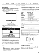
... use , the entire cooktop area may become hot. SAID code for 10-15 seconds. Touch the "+" (plus ) or "-" (minus) keypad for the desired element to turn off surface cooking area(s) individually or touch the Off keypad to the cooktop after a power failure, all surface cooking areas at once. Model/serial number plate B. To change the power level while cooking, select a power level with your mobile phone. The electronic touch controls...
... use , the entire cooktop area may become hot. SAID code for 10-15 seconds. Touch the "+" (plus ) or "-" (minus) keypad for the desired element to turn off surface cooking area(s) individually or touch the Off keypad to the cooktop after a power failure, all surface cooking areas at once. Model/serial number plate B. To change the power level while cooking, select a power level with your mobile phone. The electronic touch controls...
Use and Care
Page 6
... the surface cooking areas. Dual size C. A tone will blink. To change the heating zones being used . After 3 seconds, Control Lock Hold 3 Sec will glow to select the power level. Dual/Triple Element The dual and triple elements offer flexibility depending on by the cooktop touch controls. When finished cooking, touch ON/OFF for larger cookware, large quantities of heating zones being used while cooking, touch BURNER SIZE. 5. Single size can be turned...
... the surface cooking areas. Dual size C. A tone will blink. To change the heating zones being used . After 3 seconds, Control Lock Hold 3 Sec will glow to select the power level. Dual/Triple Element The dual and triple elements offer flexibility depending on by the cooktop touch controls. When finished cooking, touch ON/OFF for larger cookware, large quantities of heating zones being used while cooking, touch BURNER SIZE. 5. Single size can be turned...
Use and Care
Page 7
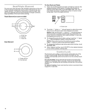
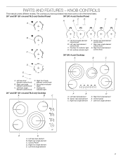
... knob C. Hot surface indicator light E. Control panel F. Cooktop On indicator light 24" and 30" (61 cm and 76.2 cm) Cooktop A B C A. Left front single element E D A. Right rear single element control knob G. Right rear single element D D. Left front single element control knob D. Left rear triple element control knob C. KNOB CONTROLS This manual covers different models. The cooktop you have purchased may have some or all of the items listed. 24" and 30" (61 cm and 76.2 cm) Control Panel 36" (91.4 cm) Control Panel C D A B E F G A B C D E F A. PARTS...
... knob C. Hot surface indicator light E. Control panel F. Cooktop On indicator light 24" and 30" (61 cm and 76.2 cm) Cooktop A B C A. Left front single element E D A. Right rear single element control knob G. Right rear single element D D. Left front single element control knob D. Left rear triple element control knob C. KNOB CONTROLS This manual covers different models. The cooktop you have purchased may have some or all of the items listed. 24" and 30" (61 cm and 76.2 cm) Control Panel 36" (91.4 cm) Control Panel C D A B E F G A B C D E F A. PARTS...
Use and Care
Page 8
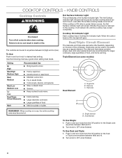
... element B. Dual element To Use Single: 1. Hot Surface Indicator Light This unit features a Hot Surface indicator light. It will glow. The dual and triple sizes combine single, dual, and outer elements and are recommended for larger cookware, large quantities of the cookware. The controls can be set to touch, even after the power is in and turn knob to the Single zone anywhere between Melt and Hi. 2. KNOB CONTROLS Cooktop Controls WARNING...
... element B. Dual element To Use Single: 1. Hot Surface Indicator Light This unit features a Hot Surface indicator light. It will glow. The dual and triple sizes combine single, dual, and outer elements and are recommended for larger cookware, large quantities of the cookware. The controls can be set to touch, even after the power is in and turn knob to the Single zone anywhere between Melt and Hi. 2. KNOB CONTROLS Cooktop Controls WARNING...
Use and Care
Page 9
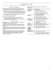
... electric cooktops, canners should be used as a guide for long periods, alternate the use of surface cooking areas, elements, or surface burners between batches. Ideal cookware should have a flat bottom, straight sides, and a well-fitting lid and the material should not extend more information, contact your local agricultural department. Cookware Aluminum Cast iron Ceramic or ceramic glass Copper Earthenware Porcelain enamelon-steel or cast iron Stainless steel...
... electric cooktops, canners should be used as a guide for long periods, alternate the use of surface cooking areas, elements, or surface burners between batches. Ideal cookware should have a flat bottom, straight sides, and a well-fitting lid and the material should not extend more information, contact your local agricultural department. Cookware Aluminum Cast iron Ceramic or ceramic glass Copper Earthenware Porcelain enamelon-steel or cast iron Stainless steel...

Use and Care
Page 10
... the bottoms of the surface cooking area may require more visible and may not glow red when an element is normal operation. This is ON. Some parts of pots and pans are clean and dry before and after each use the cooktop as a cutting board. 10 For more than 1/2" (1.3 cm) outside the area. Then, while wearing oven mitts, remove the spills using them. B A C A.
... the bottoms of the surface cooking area may require more visible and may not glow red when an element is normal operation. This is ON. Some parts of pots and pans are clean and dry before and after each use the cooktop as a cutting board. 10 For more than 1/2" (1.3 cm) outside the area. Then, while wearing oven mitts, remove the spills using them. B A C A.
Use and Care
Page 11
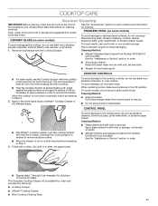
.... 1. The Complete Cooktop Cleaner Kit is available for hard water spots COOKTOP CONTROLS ■■ For best results, use abrasive cleaners, steel-wool pads, gritty washcloths, or abrasive paper towels. STAINLESS STEEL (on some models) To avoid damage to the touch. To avoid damage, do not remove seals under knobs. CERAMIC GLASS (on stains. To avoid damage to Step 2. 2. It is needed to remove stubborn stains. ■...
.... 1. The Complete Cooktop Cleaner Kit is available for hard water spots COOKTOP CONTROLS ■■ For best results, use abrasive cleaners, steel-wool pads, gritty washcloths, or abrasive paper towels. STAINLESS STEEL (on some models) To avoid damage to the touch. To avoid damage, do not remove seals under knobs. CERAMIC GLASS (on stains. To avoid damage to Step 2. 2. It is needed to remove stubborn stains. ■...
Use and Care
Page 12
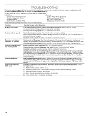
... the power of all the elements in the cooktop. 5. One or more than 15 minutes, the control panel will lock, and the F1E0 code will operate A household fuse has blown or a circuit breaker has tripped: Replace the fuse or reset the circuit breaker. Cooktop is pressed and held: Remove any objects left on again. See the Installation Instructions. See "To Use" in your correspondence. Cooktop is displaying F1E0 code Cooktop is beeping Control knob set incorrectly...
... the power of all the elements in the cooktop. 5. One or more than 15 minutes, the control panel will lock, and the F1E0 code will operate A household fuse has blown or a circuit breaker has tripped: Replace the fuse or reset the circuit breaker. Cooktop is pressed and held: Remove any objects left on again. See the Installation Instructions. See "To Use" in your correspondence. Cooktop is displaying F1E0 code Cooktop is beeping Control knob set incorrectly...
Use and Care
Page 13
... to fulfill the product warranty and provide afterwarranty service anywhere in this manual. JennAir designated service technicians are trained to local dealers, repair parts distributors, and service companies. Affresh® Stainless Steel Cleaner (stainless steel models) Order Part Number W10355016 Affresh® Kitchen and Appliance Cleaner Order Part Number W10355010 13 ASSISTANCE OR SERVICE If you need to order replacement parts, we recommend that you use only factory specified parts. Mississauga, ON L5N...
... to fulfill the product warranty and provide afterwarranty service anywhere in this manual. JennAir designated service technicians are trained to local dealers, repair parts distributors, and service companies. Affresh® Stainless Steel Cleaner (stainless steel models) Order Part Number W10355016 Affresh® Kitchen and Appliance Cleaner Order Part Number W10355010 13 ASSISTANCE OR SERVICE If you need to order replacement parts, we recommend that you use only factory specified parts. Mississauga, ON L5N...
Warranty
Page 1
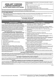
... the below named parts only and does not include repair labor. ■■ Electric element ■■ Touch Pad and microprocessor ■■ Glass ceramic cooktop: if due to or furnished with products not approved by the use inconsistent with original model/serial numbers removed, altered or not easily determined. house wiring, fuses or water inlet hoses). 4. Discoloration, rust or oxidation of surfaces resulting from...
... the below named parts only and does not include repair labor. ■■ Electric element ■■ Touch Pad and microprocessor ■■ Glass ceramic cooktop: if due to or furnished with products not approved by the use inconsistent with original model/serial numbers removed, altered or not easily determined. house wiring, fuses or water inlet hoses). 4. Discoloration, rust or oxidation of surfaces resulting from...


