
Instruction Manual
Page 1
... the best performance from your records Record the serial number, found on the back of the unit, in the space provided below. Model KAC-7251/7201 Serial number © PRINTED IN CHINA B64-2569-00/00 (KV/EV) For your new power amplifier. Familiarity with installation and operation procedures will help you call upon your KENWOOD dealer for information or service on...
... the best performance from your records Record the serial number, found on the back of the unit, in the space provided below. Model KAC-7251/7201 Serial number © PRINTED IN CHINA B64-2569-00/00 (KV/EV) For your new power amplifier. Familiarity with installation and operation procedures will help you call upon your KENWOOD dealer for information or service on...
Instruction Manual
Page 2
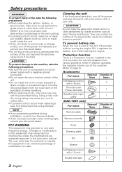
... screws (ø4 × 16 mm) 4 Terminal cover (Power terminal) 1 Speaker level input cable 1 (KAC-7251 only) Part name External View Number of the unit. • Do not install the unit in the instruction manual. Cleaning the unit If the front panel gets dirty, turn off . Safety precautions 2WARNING To prevent injury or fire, take the following precautions: • When extending the ignition, battery, or ground wires, make sure to use automotivegrade wires or other wires...
... screws (ø4 × 16 mm) 4 Terminal cover (Power terminal) 1 Speaker level input cable 1 (KAC-7251 only) Part name External View Number of the unit. • Do not install the unit in the instruction manual. Cleaning the unit If the front panel gets dirty, turn off . Safety precautions 2WARNING To prevent injury or fire, take the following precautions: • When extending the ignition, battery, or ground wires, make sure to use automotivegrade wires or other wires...
Instruction Manual
Page 3
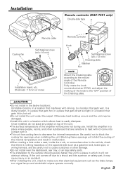
..., In a place that gets direct sunlight, In a location that electrical equipment such as a gasoline tank, brake pipe, or wiring harness, and be damaged. • Install this unit in a location which it may...make sure that gets hit by hot air) • Do not install the unit under a seat, inside the trunk, or somewhere else in which allows heat to heat will become hot during use. Installation Remote controler (KAC-7251 only) Double-side tape Cooling fan Remote cable Self-tapping screw (ø4 × 16 mm) Installation board, etc. (thickness : 15 mm or more) Remote controler...
..., In a place that gets direct sunlight, In a location that electrical equipment such as a gasoline tank, brake pipe, or wiring harness, and be damaged. • Install this unit in a location which it may...make sure that gets hit by hot air) • Do not install the unit under a seat, inside the trunk, or somewhere else in which allows heat to heat will become hot during use. Installation Remote controler (KAC-7251 only) Double-side tape Cooling fan Remote cable Self-tapping screw (ø4 × 16 mm) Installation board, etc. (thickness : 15 mm or more) Remote controler...
Instruction Manual
Page 4
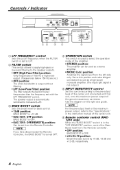
...(High-Pass Filter) position: Only frequencies of the genuine-accessory car stereo. Controls / Indicator 12 3 4 (W) 40 20 10 5 1 LPF FREQUENCY control Sets the cutoff frequency when the FILTER switch is set with this position and make bridged connections to use as a high-power monaural amplifier. (The input right signal is used as a guide. The speaker output is automatically switched to monaural (L+R). 3 BASS BOOST switch Sets the boost level for bass control. • 12dB position: BASS BOOST is +12 dB. • KAC-7201: OFF position: BASS BOOST is OFF. • KAC-7251: OFF(REMOTE...
...(High-Pass Filter) position: Only frequencies of the genuine-accessory car stereo. Controls / Indicator 12 3 4 (W) 40 20 10 5 1 LPF FREQUENCY control Sets the cutoff frequency when the FILTER switch is set with this position and make bridged connections to use as a high-power monaural amplifier. (The input right signal is used as a guide. The speaker output is automatically switched to monaural (L+R). 3 BASS BOOST switch Sets the boost level for bass control. • 12dB position: BASS BOOST is +12 dB. • KAC-7201: OFF position: BASS BOOST is OFF. • KAC-7251: OFF(REMOTE...
Instruction Manual
Page 5
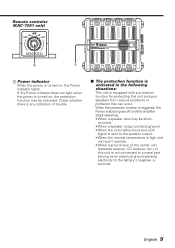
Remote controler (KAC-7251 only) dB +6 +9 OFF +12 6 7 7 Power indicator When the power is equipped with a protection function for protecting this unit is not connected to a metal part serving as an electrical ground passing electricity to the speaker output. • When the internal temperature is high and unit won't operate. • When a ground wire of trouble. ■ The protection function is activated in the following situations: This unit is turned on , the protection function may be shortcircuited...
Remote controler (KAC-7251 only) dB +6 +9 OFF +12 6 7 7 Power indicator When the power is equipped with a protection function for protecting this unit is not connected to a metal part serving as an electrical ground passing electricity to the speaker output. • When the internal temperature is high and unit won't operate. • When a ground wire of trouble. ■ The protection function is activated in the following situations: This unit is turned on , the protection function may be shortcircuited...
Instruction Manual
Page 6
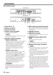
... ■ Terminal names 30 30 8 9 0! @ # $% ^ & 8 Fuse (30 A × 2) 9 Battery terminal 0 Ground terminal ! When multiple speakers are used . The speakers to a power supply which can be connected should have a maximum power output of no less than 40 W. • Do not connect the speaker output leads from the line input terminal is output. ^ REMOTE terminal (KAC-7251 only) Connects the Remote cable. Power control terminal Controls the unit ON/OFF. NOTE Use the Remote cable of the accessory. & Speaker level input terminals NOTE • The genuine-accessory car stereo shall...
... ■ Terminal names 30 30 8 9 0! @ # $% ^ & 8 Fuse (30 A × 2) 9 Battery terminal 0 Ground terminal ! When multiple speakers are used . The speakers to a power supply which can be connected should have a maximum power output of no less than 40 W. • Do not connect the speaker output leads from the line input terminal is output. ^ REMOTE terminal (KAC-7251 only) Connects the Remote cable. Power control terminal Controls the unit ON/OFF. NOTE Use the Remote cable of the accessory. & Speaker level input terminals NOTE • The genuine-accessory car stereo shall...
Instruction Manual
Page 7
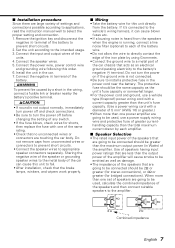
... car body. Connect the input and output wires of settings and connections possible according to applications, read the instruction manual well to install a protective fuse in the car. 7. Connect the negative - Connect the power wire, power control wire and grounding wire following this unit directly from the speakers when the engine is not connected. • Be sure to select the proper setting and connection. 1. Remove the ignition key and disconnect the negative - terminal of the speakers that no unconnected wires or connectors...
... car body. Connect the input and output wires of settings and connections possible according to applications, read the instruction manual well to install a protective fuse in the car. 7. Connect the negative - Connect the power wire, power control wire and grounding wire following this unit directly from the speakers when the engine is not connected. • Be sure to select the proper setting and connection. 1. Remove the ignition key and disconnect the negative - terminal of the speakers that no unconnected wires or connectors...

Instruction Manual
Page 8
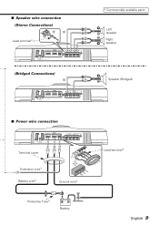
Connection ■ RCA cable or Speaker level input connection (RCA cable Connections) RCA cable ground terminal # GND # $ RCA cable* CENTER UNIT (CD receiver, etc.) Left input Right input Power control wire (Blue/ White) (Speaker level input Connections) Cable Color of the connector Left White White/Black Right Gray Gray/Black & Genuine-accessory car stereo (No line output center unit etc.) Car fuse box ■ Remote cable connection (KAC-7251 only) Remote cable ^ Battery ACC 8 English Remote controler
Connection ■ RCA cable or Speaker level input connection (RCA cable Connections) RCA cable ground terminal # GND # $ RCA cable* CENTER UNIT (CD receiver, etc.) Left input Right input Power control wire (Blue/ White) (Speaker level input Connections) Cable Color of the connector Left White White/Black Right Gray Gray/Black & Genuine-accessory car stereo (No line output center unit etc.) Car fuse box ■ Remote cable connection (KAC-7251 only) Remote cable ^ Battery ACC 8 English Remote controler
Instruction Manual
Page 9
Extension wire* Battery wire* Ground wire* Protective Fuse* Battery Lead terminal* English 9 30 ■ Speaker wire connection (Stereo Connections) @@ Lead terminal* (Bridged Connections) @ 30 * Commercially available parts Left speaker Right speaker Speaker (Bridged) 30 30 ■ Power wire connection 30 30 Terminal cover 9 0!
Extension wire* Battery wire* Ground wire* Protective Fuse* Battery Lead terminal* English 9 30 ■ Speaker wire connection (Stereo Connections) @@ Lead terminal* (Bridged Connections) @ 30 * Commercially available parts Left speaker Right speaker Speaker (Bridged) 30 30 ■ Power wire connection 30 30 Terminal cover 9 0!
Instruction Manual
Page 10
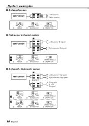
System examples ■ 2-channel system CENTER UNIT L L RR Left speaker Right speaker 2 3 4 ■ High-power 2-channel system CENTER UNIT ¡ L L L RR R L L RR ™ ¡ ™ 2 3 4 Left speaker (Bridged) Right speaker (Bridged) ■ 2-channel + Subwoofer system CENTER UNIT ¡ L L RR LINE OUT L L RR ™ Left speaker (High pass) Right speaker (High pass) Subwoofer (L + R) (Bridged) ¡2 3 4 ™ 2 3 4 10 English
System examples ■ 2-channel system CENTER UNIT L L RR Left speaker Right speaker 2 3 4 ■ High-power 2-channel system CENTER UNIT ¡ L L L RR R L L RR ™ ¡ ™ 2 3 4 Left speaker (Bridged) Right speaker (Bridged) ■ 2-channel + Subwoofer system CENTER UNIT ¡ L L RR LINE OUT L L RR ™ Left speaker (High pass) Right speaker (High pass) Subwoofer (L + R) (Bridged) ¡2 3 4 ™ 2 3 4 10 English
Instruction Manual
Page 11
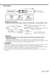
... 4 ohms may damage the unit. • Be sure to connect capacitors to speakers to set a crossover frequency of 120 Hz using a coil and capacitor...in a drop of the combined impedance with the closest ratings to the results calculated from the formula above. slope 0 dB -3 dB Crossover Frequency L C Frequency Coil (L): Passes low frequencies and blocks high frequencies. (Low pass) Capacitor (C): Passes high frequencies and blocks low frequencies. (High...
... 4 ohms may damage the unit. • Be sure to connect capacitors to speakers to set a crossover frequency of 120 Hz using a coil and capacitor...in a drop of the combined impedance with the closest ratings to the results calculated from the formula above. slope 0 dB -3 dB Crossover Frequency L C Frequency Coil (L): Passes low frequencies and blocks high frequencies. (Low pass) Capacitor (C): Passes high frequencies and blocks low frequencies. (High...
Instruction Manual
Page 12
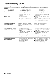
..., replace the fuse. The output level is disconnected. • Set the "BASS BOOST" switch to the "OFF (REMOTE)" position. • Connect the Remote Cable securely and correctly. 12 English The sound quality is bad. (The sound is distorted.) • The speakers wire are disconnected. • Protection circuit may be activated. • Volume is too high. • The speaker cord is not set improperly. • Connect them properly checking the + / - The Remote Controller does not function. • The "BASS BOOST" switch...
..., replace the fuse. The output level is disconnected. • Set the "BASS BOOST" switch to the "OFF (REMOTE)" position. • Connect the Remote Cable securely and correctly. 12 English The sound quality is bad. (The sound is distorted.) • The speakers wire are disconnected. • Protection circuit may be activated. • Volume is too high. • The speaker cord is not set improperly. • Connect them properly checking the + / - The Remote Controller does not function. • The "BASS BOOST" switch...
Instruction Manual
Page 13
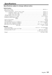
...; 2 Bridged (4 Ω) (1 kHz, 0.8 % THD 460 W × 1 Frequency Response (+0, -3 dB 5 Hz - 50 kHz Sensitivity (rated output) (MAX 0.2 V Sensitivity (rated output) (MIN 5.0 V Signal to change without notice. Specifications Specifications subject to Noise Ratio...100 dB Input Impedance...10 kΩ Low Pass Filter Frequency (18 dB/oct 50 - 200 Hz (variable) High Pass Filter Frequency (12 dB/oct 150 Hz Bass Boost Circuit (90 Hz) KAC-7251 OFF / +6 / +9 / +12 dB Bass Boost Circuit (90 Hz) KAC...
...; 2 Bridged (4 Ω) (1 kHz, 0.8 % THD 460 W × 1 Frequency Response (+0, -3 dB 5 Hz - 50 kHz Sensitivity (rated output) (MAX 0.2 V Sensitivity (rated output) (MIN 5.0 V Signal to change without notice. Specifications Specifications subject to Noise Ratio...100 dB Input Impedance...10 kΩ Low Pass Filter Frequency (18 dB/oct 50 - 200 Hz (variable) High Pass Filter Frequency (12 dB/oct 150 Hz Bass Boost Circuit (90 Hz) KAC-7251 OFF / +6 / +9 / +12 dB Bass Boost Circuit (90 Hz) KAC...


