
User Guide
Page 8
... (Waste Electrical and Electronic Equipment) Statement v Chapter 1 Getting Started 1-1 Mainboard Specifications 1-2 Mainboard Layout 1-4 Packing Checklist 1-5 Chapter 2 Hardware Setup 2-1 Quick Components Guide 2-2 CPU (Central Processing Unit 2-3 Memory 2-6 Power Supply 2-8 Back Panel 2-9 Connectors 2-11 Jumpers 2-19 Switch 2-20 Slots 2-21 LED Status Indicators 2-24 Chapter 3 BIOS Setup 3-1 Entering Setup 3-2 The Main Menu 3-4 Standard...
... (Waste Electrical and Electronic Equipment) Statement v Chapter 1 Getting Started 1-1 Mainboard Specifications 1-2 Mainboard Layout 1-4 Packing Checklist 1-5 Chapter 2 Hardware Setup 2-1 Quick Components Guide 2-2 CPU (Central Processing Unit 2-3 Memory 2-6 Power Supply 2-8 Back Panel 2-9 Connectors 2-11 Jumpers 2-19 Switch 2-20 Slots 2-21 LED Status Indicators 2-24 Chapter 3 BIOS Setup 3-1 Entering Setup 3-2 The Main Menu 3-4 Standard...
User Guide
Page 11
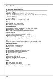
...174; SB710 chipset Integrated Graphic ■ Integrated ATI RadeonTM HD4200 GPU (for AMD® 785G chipset) ■ Share Memory: Max up to 512MB ■ 1 Gb DDR3 1333 side port memory integrated (optional) Memory Support ■ DDR3 1333/ 1066/ 800 SDRAM (total 16 GB Max) ■ 4 DDR3 DIMMs (240-pin.../ 1.5V) (For more information on compatible components, please visit http://www.msi.com/index.php?func=testreport) LAN ■ ...
...174; SB710 chipset Integrated Graphic ■ Integrated ATI RadeonTM HD4200 GPU (for AMD® 785G chipset) ■ Share Memory: Max up to 512MB ■ 1 Gb DDR3 1333 side port memory integrated (optional) Memory Support ■ DDR3 1333/ 1066/ 800 SDRAM (total 16 GB Max) ■ 4 DDR3 DIMMs (240-pin.../ 1.5V) (For more information on compatible components, please visit http://www.msi.com/index.php?func=testreport) LAN ■ ...

User Guide
Page 20
...DIMM1 DIMM2 DIMM3 DIMM4 2 DIMM1 DIMM2 DIMM3' DIMM4 Installed Empty Important • DDR3 memory modules are used for installing memory modules. For more information on compatible components, please visit http://www.msi.com/index.php?func=testreport DDR3 240-pin, 1.5V 72x2=144 pin 48x2=96 pin... Dual-Channel mode Population Rule In Dual-Channel mode, the memory modules can enhance the system performance. Enabling Dual-Channel...
...DIMM1 DIMM2 DIMM3 DIMM4 2 DIMM1 DIMM2 DIMM3' DIMM4 Installed Empty Important • DDR3 memory modules are used for installing memory modules. For more information on compatible components, please visit http://www.msi.com/index.php?func=testreport DDR3 240-pin, 1.5V 72x2=144 pin 48x2=96 pin... Dual-Channel mode Population Rule In Dual-Channel mode, the memory modules can enhance the system performance. Enabling Dual-Channel...
User Guide
Page 21
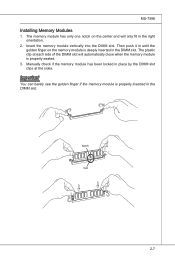
...the center and will only fit in place by the DIMM slot clips at each side of the DIMM slot will automatically close when the memory module is properly inserted in the DIMM slot. The plastic clip at the sides. Notch Volt 2-7 Manually check if the... memory module has been locked in the right orientation. 2. MS-7596 Installing Memory Modules 1. Important You can barely see the golden finger if the memory module is properly seated. 3. The memory module has only one notch on the memory module is deeply inserted in the DIMM slot...
...the center and will only fit in place by the DIMM slot clips at each side of the DIMM slot will automatically close when the memory module is properly inserted in the DIMM slot. The plastic clip at the sides. Notch Volt 2-7 Manually check if the... memory module has been locked in the right orientation. 2. MS-7596 Installing Memory Modules 1. Important You can barely see the golden finger if the memory module is properly seated. 3. The memory module has only one notch on the memory module is deeply inserted in the DIMM slot...

User Guide
Page 36
... "Enable CrossFire™". 5. To avoid the issue, please follow the steps below to http://game.amd.com/us-en/crossfirex_hybrid.aspx Important Changing integrated graphic memory operating mode may cause Hybrid CrossFireX™ fail. Select the Advanced View from the view drop menu. 2. From the "Graphics Adapter" list, select the graphics...
... "Enable CrossFire™". 5. To avoid the issue, please follow the steps below to http://game.amd.com/us-en/crossfirex_hybrid.aspx Important Changing integrated graphic memory operating mode may cause Hybrid CrossFireX™ fail. Select the Advanced View from the view drop menu. 2. From the "Graphics Adapter" list, select the graphics...

User Guide
Page 40
... screen, press key to the date this chapter are under continuous update for reference only. • Upon boot-up, the 1st line appearing after the memory count is usually in this BIOS was released. 3-2 Important • The items under each BIOS category described in the format: A7596AMS V2.0 050509 where: 1st...
... screen, press key to the date this chapter are under continuous update for reference only. • Upon boot-up, the 1st line appearing after the memory count is usually in this BIOS was released. 3-2 Important • The items under each BIOS category described in the format: A7596AMS V2.0 050509 where: 1st...

User Guide
Page 46
▍ BIOS Setup ▶ Hold On The setting determines whether the system will halt on for any detected error. ▶ System Information Press to enter the sub-menu, and the following screen appears. When the system stops for the errors preset, it will stop if an error is detected. [No Error] The system does not stop for 15 seconds and then automatically resume its operation. [All Error] The system stops when any error is detected at boot. This sub-menu shows the CPU information, BIOS version and memory status of your system (read only). 3-8
▍ BIOS Setup ▶ Hold On The setting determines whether the system will halt on for any detected error. ▶ System Information Press to enter the sub-menu, and the following screen appears. When the system stops for the errors preset, it will stop if an error is detected. [No Error] The system does not stop for 15 seconds and then automatically resume its operation. [All Error] The system stops when any error is detected at boot. This sub-menu shows the CPU information, BIOS version and memory status of your system (read only). 3-8

User Guide
Page 49
...if the system fails to boot from the system memory or sideport memory. Setting to [UMA+SIDEPORT], allocates both system memory and sideport memory for onboard VGA. Setting to [SIDEPORT], allocates the sideport memory for onboard VGA. ▶ VGA Share Memory The system shares memory to the onboard VGA card. Setting to [... in MHz). ▶ UMA-SP Interleave Mode This item allows you to set the SIDEPORT memory frequency (in system memory. ▶ On-chip VGA This item specifies whether to allocate the memory for onboard VGA. MS-7596 ▶ UMA Location This item is used to select the...
...if the system fails to boot from the system memory or sideport memory. Setting to [UMA+SIDEPORT], allocates both system memory and sideport memory for onboard VGA. Setting to [SIDEPORT], allocates the sideport memory for onboard VGA. ▶ VGA Share Memory The system shares memory to the onboard VGA card. Setting to [... in MHz). ▶ UMA-SP Interleave Mode This item allows you to set the SIDEPORT memory frequency (in system memory. ▶ On-chip VGA This item specifies whether to allocate the memory for onboard VGA. MS-7596 ▶ UMA Location This item is used to select the...

User Guide
Page 52
... function. In this state, no system context is ACPI-aware, such as Windows 2000/ XP, you can choose to enter the Standby mode in memory will be used to restore the system when a "wake up" event occurs. 3-14 The information stored in S1(POS) or S3(STR) fashion... through the setting of system configuration and open applications/files is saved to main memory that remains powered while most other hardware components turn off to activate the ACPI (Advanced Configuration and Power Management Interface) Function. If your operating...
... function. In this state, no system context is ACPI-aware, such as Windows 2000/ XP, you can choose to enter the Standby mode in memory will be used to restore the system when a "wake up" event occurs. 3-14 The information stored in S1(POS) or S3(STR) fashion... through the setting of system configuration and open applications/files is saved to main memory that remains powered while most other hardware components turn off to activate the ACPI (Advanced Configuration and Power Management Interface) Function. If your operating...

User Guide
Page 55
A message will show up to six characters in length, and press . This prevents an unauthorized person from CMOS memory. When a password has been set, you will be disabled. Retype the password and press . To clear a set password, just press when you are prompted to ...
A message will show up to six characters in length, and press . This prevents an unauthorized person from CMOS memory. When a password has been set, you will be disabled. Retype the password and press . To clear a set password, just press when you are prompted to ...

User Guide
Page 56
Read-only. ▶ CPU Specifications Press to enter the sub-menu and the following screen appears. This submenu shows the information of CPU and Memory speed. ▍ BIOS Setup Cell Menu Important Change these settings only if you are familiar with the chipset. ▶ Current CPU / DRAM Frequency These items show the current clocks of installed CPU. 3-18
Read-only. ▶ CPU Specifications Press to enter the sub-menu and the following screen appears. This submenu shows the information of CPU and Memory speed. ▍ BIOS Setup Cell Menu Important Change these settings only if you are familiar with the chipset. ▶ Current CPU / DRAM Frequency These items show the current clocks of installed CPU. 3-18

User Guide
Page 58
... ▶ Adjust CPU-NB Ratio This item is available only when the processor supports this function. ▶ Memory-Z Press to enter the sub-menu and the following screen appears. ▶ DIMM1~4 Memory SPD Information Press to adjust CPU-NB ratio. ▶ Adjusted CPU Frequency (MHz) It shows the adjusted ...Front Side Bus clock frequency (in MHz). ▶ Adjust CPU Ratio This item is for overclock. This submenu displays the information of installed memory. 3-20 Read-only. ▶ Advanced Clock Calibration This item is used to enter the sub-menu and the following screen appears.
... ▶ Adjust CPU-NB Ratio This item is available only when the processor supports this function. ▶ Memory-Z Press to enter the sub-menu and the following screen appears. ▶ DIMM1~4 Memory SPD Information Press to adjust CPU-NB ratio. ▶ Adjusted CPU Frequency (MHz) It shows the adjusted ...Front Side Bus clock frequency (in MHz). ▶ Adjust CPU Ratio This item is for overclock. This submenu displays the information of installed memory. 3-20 Read-only. ▶ Advanced Clock Calibration This item is used to enter the sub-menu and the following screen appears.

User Guide
Page 59
...feature is used to Integrate two 64-bit DCTs into a 128-bit interface. ▶ Bank Interleaving Bank Interleaving is a memory power-saving technology. When the system does not access memory over a period of the DRAM timing. If you set this field to [DCT 0], [DCT 1] or [Both], ...following screen appears. ▶ DRAM Timing Mode This field has the capacity to automatically detect all of time, it will automatically reduce the memory power supply. ▶ MemClk Tristate C3/ATLVID This setting allows you to enable/disable the MemClk Tristating during overclocking. ▶ DRAM Advance...
...feature is used to Integrate two 64-bit DCTs into a 128-bit interface. ▶ Bank Interleaving Bank Interleaving is a memory power-saving technology. When the system does not access memory over a period of the DRAM timing. If you set this field to [DCT 0], [DCT 1] or [Both], ...following screen appears. ▶ DRAM Timing Mode This field has the capacity to automatically detect all of time, it will automatically reduce the memory power supply. ▶ MemClk Tristate C3/ATLVID This setting allows you to enable/disable the MemClk Tristating during overclocking. ▶ DRAM Advance...

User Guide
Page 60
... [Auto], the system will detect the HT link speed automatically. ▶ Adjust PCI-E Frequency (MHz) This field allows you to adjust the voltage of CPU, Memory and chipset. 3-22 Setting to [Auto], the system will remove (turn off) clocks from empty DRAM/ PCI slots to minimize the electromagnetic interference (EMI). ▶...). ▶ Auto Disable DRAM/PCI Frequency When set the Hyper-Transport Link speed. ▍ BIOS Setup ▶ Adjusted DRAM Frequency (MHz) It shows the adjusted Memory frequency.
... [Auto], the system will detect the HT link speed automatically. ▶ Adjust PCI-E Frequency (MHz) This field allows you to adjust the voltage of CPU, Memory and chipset. 3-22 Setting to [Auto], the system will remove (turn off) clocks from empty DRAM/ PCI slots to minimize the electromagnetic interference (EMI). ▶...). ▶ Auto Disable DRAM/PCI Frequency When set the Hyper-Transport Link speed. ▍ BIOS Setup ▶ Adjusted DRAM Frequency (MHz) It shows the adjusted Memory frequency.

User Guide
Page 96
DotNet Frame Work 2.0 B-C-1 Operation system: Windows XP or up. 4. DVD-ROM drive for software installation. 3. Before you install the Overclocking Center, please make sure the system has meet the following requirements: 1. 256MB system memory. 2. Appendix C Overclocking Center Overclocking Center, the most useful and powerful utility that MSI has spent much research and efforts to develop, helps users to monitor or configure the hardware status of MSI Mainboard in windows, such as CPU clock, voltage, fan speed and temperature.
DotNet Frame Work 2.0 B-C-1 Operation system: Windows XP or up. 4. DVD-ROM drive for software installation. 3. Before you install the Overclocking Center, please make sure the system has meet the following requirements: 1. 256MB system memory. 2. Appendix C Overclocking Center Overclocking Center, the most useful and powerful utility that MSI has spent much research and efforts to develop, helps users to monitor or configure the hardware status of MSI Mainboard in windows, such as CPU clock, voltage, fan speed and temperature.

User Guide
Page 98
Important The pictures in this appendix are for detailed information. MS-7596 System Info In the System Info screen, you purchased. Motherboard Click Motherboard to the appearance of motherboard/ memory/ PCI. Please refer to read the information of your system for reference only and may vary from the product you can read the information of motherboard, BIOS, installed CPU and installed graphics card. C-3
Important The pictures in this appendix are for detailed information. MS-7596 System Info In the System Info screen, you purchased. Motherboard Click Motherboard to the appearance of motherboard/ memory/ PCI. Please refer to read the information of your system for reference only and may vary from the product you can read the information of motherboard, BIOS, installed CPU and installed graphics card. C-3

User Guide
Page 99
▍ Overclocking Center Memory Click Memory to read from the SPD list. You can select a DIMM slot you want to read the information of each memory DIMM slot. PCI Click PCI to read the information of devices on the mainboard. C-4
▍ Overclocking Center Memory Click Memory to read from the SPD list. You can select a DIMM slot you want to read the information of each memory DIMM slot. PCI Click PCI to read the information of devices on the mainboard. C-4


