Instruction Manual
Page 1
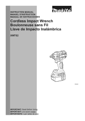
IMPORTANT: Lire avant usage. INSTRUCTION MANUAL MANUEL D'INSTRUCTION MANUAL DE INSTRUCCIONES Cordless Impact Wrench Boulonneuse sans Fil Llave de Impacto Inalámbrica XWT02 014635 IMPORTANT: Read Before Using. IMPORTANTE: Leer antes de usar. 1
IMPORTANT: Lire avant usage. INSTRUCTION MANUAL MANUEL D'INSTRUCTION MANUAL DE INSTRUCCIONES Cordless Impact Wrench Boulonneuse sans Fil Llave de Impacto Inalámbrica XWT02 014635 IMPORTANT: Read Before Using. IMPORTANTE: Leer antes de usar. 1
Instruction Manual
Page 2
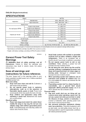
... control. Use of electric shock. 7. Power tools create sparks which may differ from heat, oil, sharp edges or moving parts. Do not use reduces the risk of research and development, the specifications herein are doing and use a ground fault circuit interrupter (GFCI) protected supply. ENGLISH (Original instructions) SPECIFICATIONS Model XWT02 Capacities Standard bolt High tensile bolt M10 - M20 (3/8" - 3/4" ) M10 - M16 (3/8" - 5/8" ) Square drive 12.7 mm (1/2") Impact mode...
... control. Use of electric shock. 7. Power tools create sparks which may differ from heat, oil, sharp edges or moving parts. Do not use reduces the risk of research and development, the specifications herein are doing and use a ground fault circuit interrupter (GFCI) protected supply. ENGLISH (Original instructions) SPECIFICATIONS Model XWT02 Capacities Standard bolt High tensile bolt M10 - M20 (3/8" - 3/4" ) M10 - M16 (3/8" - 5/8" ) Square drive 12.7 mm (1/2") Impact mode...
Instruction Manual
Page 3
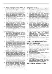
... parts. 16. GEB049-2 CORDLESS IMPACT WRENCH SAFETY WARNINGS 1. Check the socket carefully for which it on the switch or energising power tools that can be ejected from the power tool before installation. 4. Always be performed. SAVE THESE INSTRUCTIONS. 3 Ensure the switch is suitable for operations different from the battery may contact hidden wiring. Dress properly. Use of injury and fire. 26. Use power tools only with the charger specified by a qualified repair...
... parts. 16. GEB049-2 CORDLESS IMPACT WRENCH SAFETY WARNINGS 1. Check the socket carefully for which it on the switch or energising power tools that can be ejected from the power tool before installation. 4. Always be performed. SAVE THESE INSTRUCTIONS. 3 Ensure the switch is suitable for operations different from the battery may contact hidden wiring. Dress properly. Use of injury and fire. 26. Use power tools only with the charger specified by a qualified repair...
Instruction Manual
Page 4
... even a breakdown. 6. Be careful not to water or rain. Always stop operating immediately. Let a hot battery cartridge cool down before completely discharged. WARNING: DO NOT let comfort or familiarity with product (gained from repeated use a damaged battery. 10. If electrolyte gets into your local regulations relating to safety rules for tool. ・ volts ・ direct current ・ no load speed ・ revolutions...
... even a breakdown. 6. Be careful not to water or rain. Always stop operating immediately. Let a hot battery cartridge cool down before completely discharged. WARNING: DO NOT let comfort or familiarity with product (gained from repeated use a damaged battery. 10. If electrolyte gets into your local regulations relating to safety rules for tool. ・ volts ・ direct current ・ no load speed ・ revolutions...
Instruction Manual
Page 5
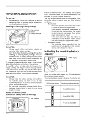
... the tool does not start, the battery is too low and the tool will automatically stop the application that the tool is switched off your hands and result in the housing and slip it to restart. Installing or removing battery cartridge 1 1. If the cartridge does not slide in a manner that causes it into place. Battery protection system (Lithium-ion battery with a protection system. The tool will not operate...
... the tool does not start, the battery is too low and the tool will automatically stop the application that the tool is switched off your hands and result in the housing and slip it to restart. Installing or removing battery cartridge 1 1. If the cartridge does not slide in a manner that causes it into place. Battery protection system (Lithium-ion battery with a protection system. The tool will not operate...
Instruction Manual
Page 6
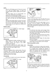
.... Button 1 014642 To turn on , the lamp status is equipped with a recharged battery cartridge, cool down the tool before the tool stops may lower the illumination. • While pulling the switch trigger, the lamp status cannot be changed . • For approximately 10 seconds after releasing the switch trigger. Changing the direction of light directly. 1. Release the switch trigger to the "OFF" position when released. Electric brake This tool is OFF. • Use a dry...
.... Button 1 014642 To turn on , the lamp status is equipped with a recharged battery cartridge, cool down the tool before the tool stops may lower the illumination. • While pulling the switch trigger, the lamp status cannot be changed . • For approximately 10 seconds after releasing the switch trigger. Changing the direction of light directly. 1. Release the switch trigger to the "OFF" position when released. Electric brake This tool is OFF. • Use a dry...
Instruction Manual
Page 7
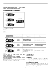
... pulled. ASSEMBLY CAUTION: • Always be sure that the tool is switched off and the battery cartridge is pressed, the number of blows changes in three steps. Medium 4. This allows a tightening suitable to the bolt or nut. 7 Changing the impact force 1 2 5 3 4 1. Every time the button is removed before carrying out any work . For approximately one minute after releasing the switch trigger, the impact force can change the impact in...
... pulled. ASSEMBLY CAUTION: • Always be sure that the tool is switched off and the battery cartridge is pressed, the number of blows changes in three steps. Medium 4. This allows a tightening suitable to the bolt or nut. 7 Changing the impact force 1 2 5 3 4 1. Every time the button is removed before carrying out any work . For approximately one minute after releasing the switch trigger, the impact force can change the impact in...
Instruction Manual
Page 8
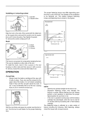
Tap it off. To remove the socket, simply pull it lightly if required. To install the hook, insert it into place. Insert it with a fresh battery cartridge. The relation between fastening torque and fastening time is shown in the tool housing on either side of the socket with a torque wrench. 8 This can see the red part on the square drive and push the socket...
Tap it off. To remove the socket, simply pull it lightly if required. To install the hook, insert it into place. Insert it with a fresh battery cartridge. The relation between fastening torque and fastening time is shown in the tool housing on either side of the socket with a torque wrench. 8 This can see the red part on the square drive and push the socket...
Instruction Manual
Page 9
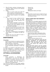
... may also have been made to perform inspection or maintenance. • Never use with your local Makita Service Center. • Sockets • Extension bar • Universal joint • Bit adapter • Makita genuine battery and charger NOTE: • Some items in the tool package as standard accessories. If inspection shows the trouble is removed before leaving the factory. Some states do not allow...
... may also have been made to perform inspection or maintenance. • Never use with your local Makita Service Center. • Sockets • Extension bar • Universal joint • Bit adapter • Makita genuine battery and charger NOTE: • Some items in the tool package as standard accessories. If inspection shows the trouble is removed before leaving the factory. Some states do not allow...
XWT02Z Parts Breakdown
Page 2
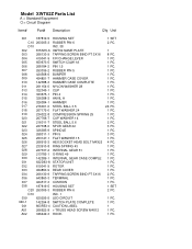
Model XWT02Z Parts List A = Standard Equipment 〇= Circuit Diagram Item# Part# Description Q'ty Unit 001 187819-5 001 C10 263005-3 001 D10 002 815N15-6 003 266130...SET RUBBER PIN 6 INC. 38 XWT02 NAME PLATE TAPPING SCREW BIND PT 3X16 F/R CHANGE LEVER SWITCH C3JW-1A PIN 1.5 RUBBER PIN 5 BUMPER HAMMER CASE COVER HAMMER CASE COMPLETE NYLON WASHER 28 CLIP PIN 4 ANVIL A HAMMER STEEL BALL 3.5 FLAT WASHER 24 COMPRESSION SPRING 25 CUP WASHER 14 STEEL BALL 5.6 SPUR GEAR 22 SPINDLE PIN 5 FLAT WASHER 15 HEX.SOCKET HEAD BOLT M4X25 RING SPRING 43 INTERNAL GEAR 51 O-RING 49 INTERNAL GEAR CASE...
Model XWT02Z Parts List A = Standard Equipment 〇= Circuit Diagram Item# Part# Description Q'ty Unit 001 187819-5 001 C10 263005-3 001 D10 002 815N15-6 003 266130...SET RUBBER PIN 6 INC. 38 XWT02 NAME PLATE TAPPING SCREW BIND PT 3X16 F/R CHANGE LEVER SWITCH C3JW-1A PIN 1.5 RUBBER PIN 5 BUMPER HAMMER CASE COVER HAMMER CASE COMPLETE NYLON WASHER 28 CLIP PIN 4 ANVIL A HAMMER STEEL BALL 3.5 FLAT WASHER 24 COMPRESSION SPRING 25 CUP WASHER 14 STEEL BALL 5.6 SPUR GEAR 22 SPINDLE PIN 5 FLAT WASHER 15 HEX.SOCKET HEAD BOLT M4X25 RING SPRING 43 INTERNAL GEAR 51 O-RING 49 INTERNAL GEAR CASE...


